2 layers100 × 80.2 mm
 pavan1713/Magnetic_encoder_node
This repository contains the hardware design and proposed firmware architecture for a compact, robust industrial encoder node intended for robotic and automation systems.
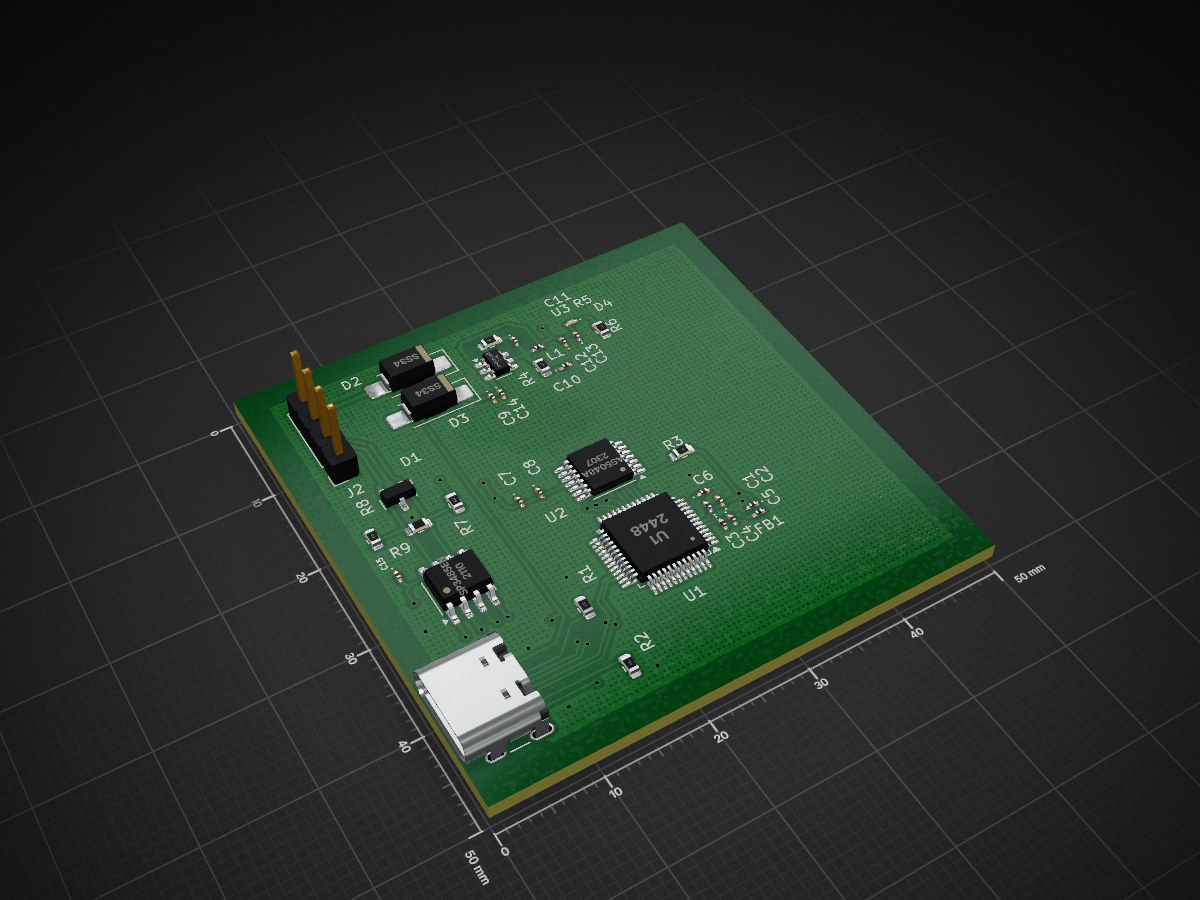
Magnetic encoder node is an open-source printed circuit board by pavan1713, from the pavan1713/Magnetic_encoder_node repository on GitHub. It is a 4-layer board of 50 × 50 mm with 36 parts on 71 nets, routed with 272 tracks and 27 vias.
It is built around the AP63203WU, AS5048A and SP3485EN-Y, with the SS34 among its other parts. Its parts include 15 capacitors, 9 resistors, 4 ICs, 4 diodes and 2 connectors.


Industrial Magnetic Encoder NodeProject Type: Hardware Design & Firmware Architecture (Stage 2 Task)
Target Date: 19-06-2026
Project OverviewThis repository contains the hardware design and proposed firmware architecture for a compact, robust industrial encoder node intended for robotic and automation systems. The node is designed to read continuous angular position data from a magnetic rotary encoder and reliably transmit it to a host controller over an RS485 multidrop network.
The system is optimized for deployment in electrically noisy industrial environments, specifically in close proximity to BLDC motors and switching power electronics. It leverages high-resolution 14-bit sensing capable of 0.0219° precision.
Key Technical Highlights1. Hardware Architecture2. Firmware & Communication3. Reliability & ProtectionRepository Structure & DeliverablesHardware (/hardware)Native KiCad V9.0 project files and manufacturing outputs.
| Deliverable | Location | Description |
|---|---|---|
| Native Project | /hardware | KiCad V9.0 project (.kicad_pro), schematic, and PCB. |
| Gerber Files | /hardware/gerbers | Production-ready Gerber and drill files (X2 format). |
| SVG Exports | /hardware/gerbers_svg | Visual plots of the board layers. |
| BOM | /hardware/BOM/ | Detailed Bill of Materials for assembly. |
Documentation (/docs)Comprehensive design justifications and operational procedures.
| Document | Link | Description |
|---|---|---|
| Design Document | Design Document | Component selection, power justification, and EMI strategy. |
| Firmware Spec | Firmware Architecture | RTOS task scheduling, DMA allocation, and data flow. |
| Protocol Spec | Protocol Specification | RS485 packet format, CRC-16, and SPI timing. |
| Risk Analysis | Reliability Report | FMEA, dual-power analysis, and failure mitigation. |
| Assumptions | Design Trade-offs | Open questions for production and mechanical constraints. |
Operational Notes/docs directory.| Qty | Value | Footprint | References |
|---|---|---|---|
| 5 | 100n | Diode_SMD:D_0201_0603Metric_Pad0.64x0.40mm_HandSolder | C1, C2, C6, C7, C15 |
| 3 | 22uf | Diode_SMD:D_0201_0603Metric_Pad0.64x0.40mm_HandSolder | C9, C12, C13 |
| 2 | 0.1uf | Diode_SMD:D_0201_0603Metric_Pad0.64x0.40mm_HandSolder | C11, C14 |
| 2 | 10R | Resistor_SMD:R_0603_1608Metric | R4, R5 |
| 2 | 1u | Diode_SMD:D_0201_0603Metric_Pad0.64x0.40mm_HandSolder | C3, C5 |
| 2 | 4K7 | Resistor_SMD:R_0603_1608Metric | R7, R8 |
| 2 | SS34 | Diode_SMD:D_SMA_Handsoldering | D2, D3 |
| 1 | 100pf | Diode_SMD:D_0201_0603Metric_Pad0.64x0.40mm_HandSolder | C10 |
| 1 | 10K | Resistor_SMD:R_0603_1608Metric | R3 |
| 1 | 10n | Diode_SMD:D_0201_0603Metric_Pad0.64x0.40mm_HandSolder | C4 |
| 1 | 10uf | Diode_SMD:D_0201_0603Metric_Pad0.64x0.40mm_HandSolder | C8 |
| 1 | 1k | Resistor_SMD:R_0603_1608Metric | R6 |
| 1 | 5K1 | Resistor_SMD:R_0603_1608Metric | R2 |
| 1 | 5k1 | Resistor_SMD:R_0603_1608Metric | R1 |
| 1 | 6.8uh | Inductor_SMD:L_0201_0603Metric_Pad0.64x0.40mm_HandSolder | L1 |
| 1 | AP63203WU | Package_TO_SOT_SMD:TSOT-23-6 | U3 |
| 1 | AS5048A | Package_SO:TSSOP-14_4.4x5mm_P0.65mm | U2 |
| 1 | Conn_01x04_Pin | Connector_PinSocket_2.54mm:PinSocket_1x04_P2.54mm_Vertical | J2 |
| 1 | FerriteBead | Inductor_SMD:L_0201_0603Metric_Pad0.64x0.40mm_HandSolder | FB1 |
| 1 | Green | LED_SMD:LED_0201_0603Metric_Pad0.64x0.40mm_HandSolder | D4 |
| 1 | J3 | Connector_USB:USB_C_Receptacle_GCT_USB4105-xx-A_16P_TopMnt_Horizontal | J3 |
| 1 | R9 | Resistor_SMD:R_0603_1608Metric | R9 |
| 1 | SM712_SOT23 | Package_TO_SOT_SMD:SOT-23 | D1 |
| 1 | SP3485EN | Package_SO:SOIC-8_3.9x4.9mm_P1.27mm | U4 |
| 1 | U1 | Package_QFP:LQFP-48_7x7mm_P0.5mm | U1 |
It measures 50 × 50 mm and has 4 copper layers, 1.6 mm thick.
36 parts, built around the AP63203WU, AS5048A, SP3485EN-Y and SS34. The full list of its parts is on this page, with links to each part's symbol and footprint where PCBKit's library has them.
From the pavan1713/Magnetic_encoder_node repository on GitHub, at the commit this page was made from: the board is hardware/magnetic_encoder_node.kicad_pcb and its schematic hardware/magnetic_encoder_node.kicad_sch. PCBKit opens the board in the browser, with nothing to install.
Its repository states no licence, so its author keeps all rights: ask pavan1713 before reusing the design.

Fluepke/Fluepdot
Project for controlling Annax flipdot panels used by the Berliner Verkehrsbetriebe


arcnode-io/dlr-rtu-pcb
Solar-powered RTU sensor HAT for transmission tower DLR deployment

moinsen-dev/open-bed-climate
Open-source, local-first bed climate system: water-cooled/heated mat, standard parts, DIY kits, Home Assistant. Design phase.

nguyenduchan/fiberboard
Fiberboard là bo mạch điều khiển logic tích hợp (AIO), không có driver stepper Nema. Cùng chức năng module ESP32 công nghiệp thông dụng: 4 ngõ vào cách ly + 4 relay + RS485.