
2 layers304.8 × 170.8 mm
 patrickhener/rummikub-timer
A Rummikub Timer Project
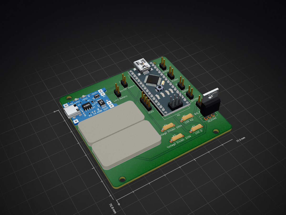
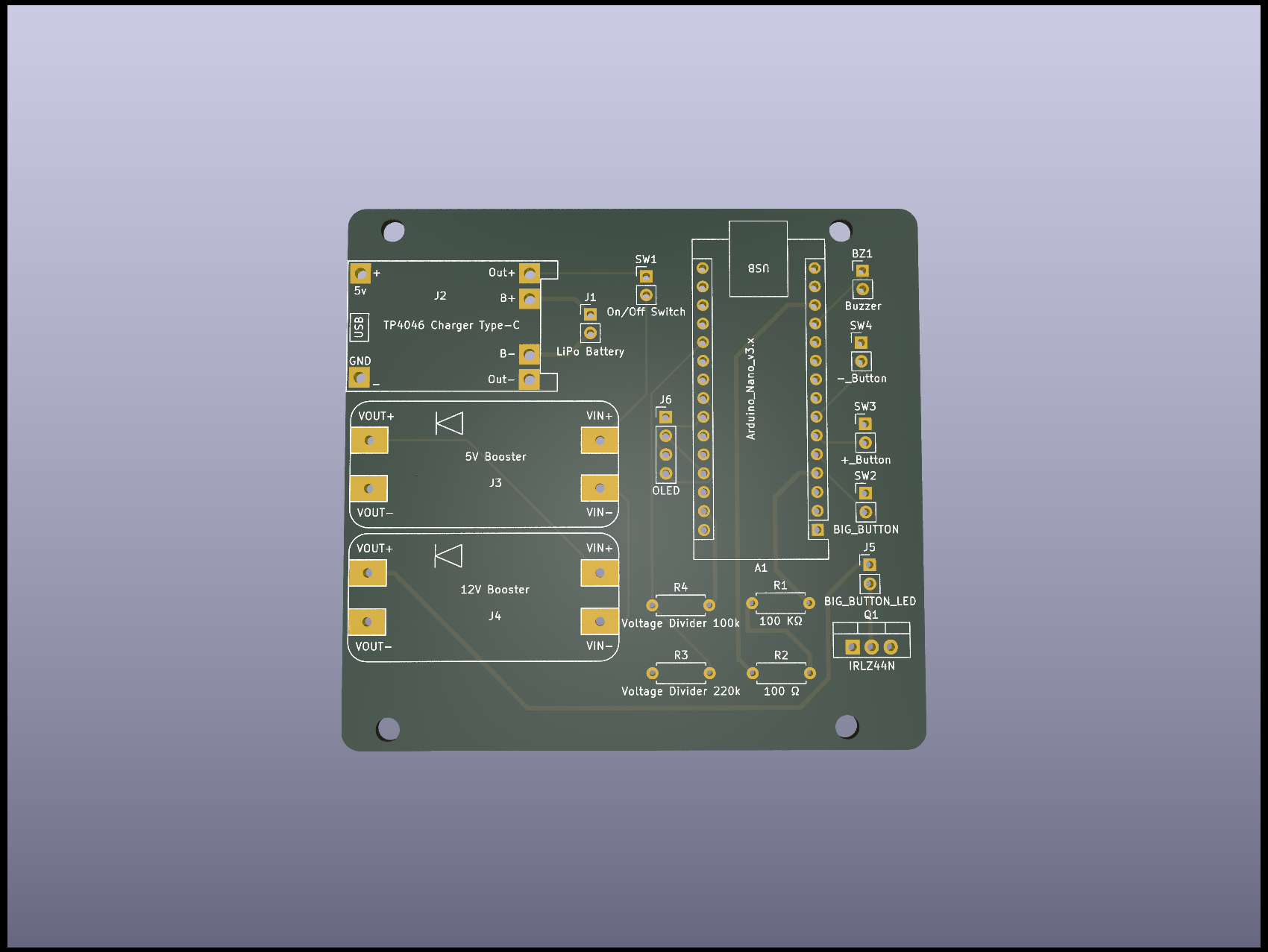
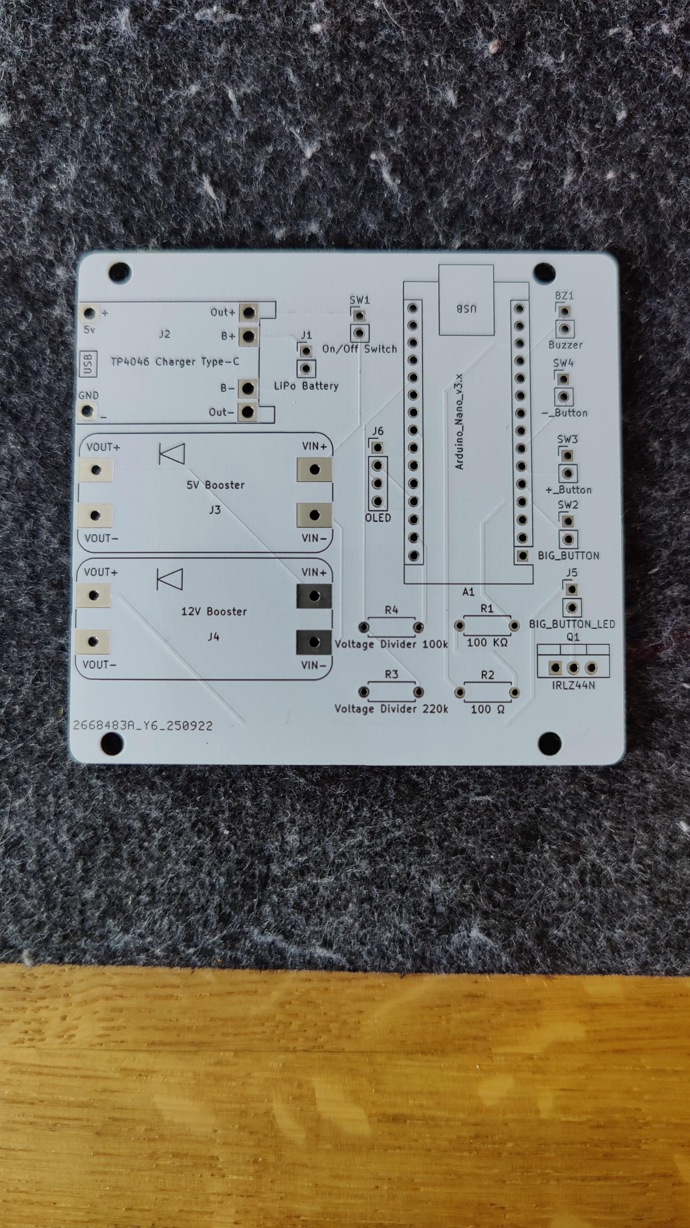
Rummikub timer is an open-source printed circuit board by patrickhener, from the patrickhener/rummikub-timer repository on GitHub. It is a 2-layer board of 77.5 × 72.9 mm with 17 parts on 38 nets, routed with 66 tracks and 0 vias.
It is built around the IRLZ44N. Its parts include 6 connectors, 4 resistors, 4 switches and 1 transistor. It belongs with the AVR (ATmega, ATtiny) boards of this library.
This project is a Rummikub timer. It has the following functions:
The project consists of the following components:
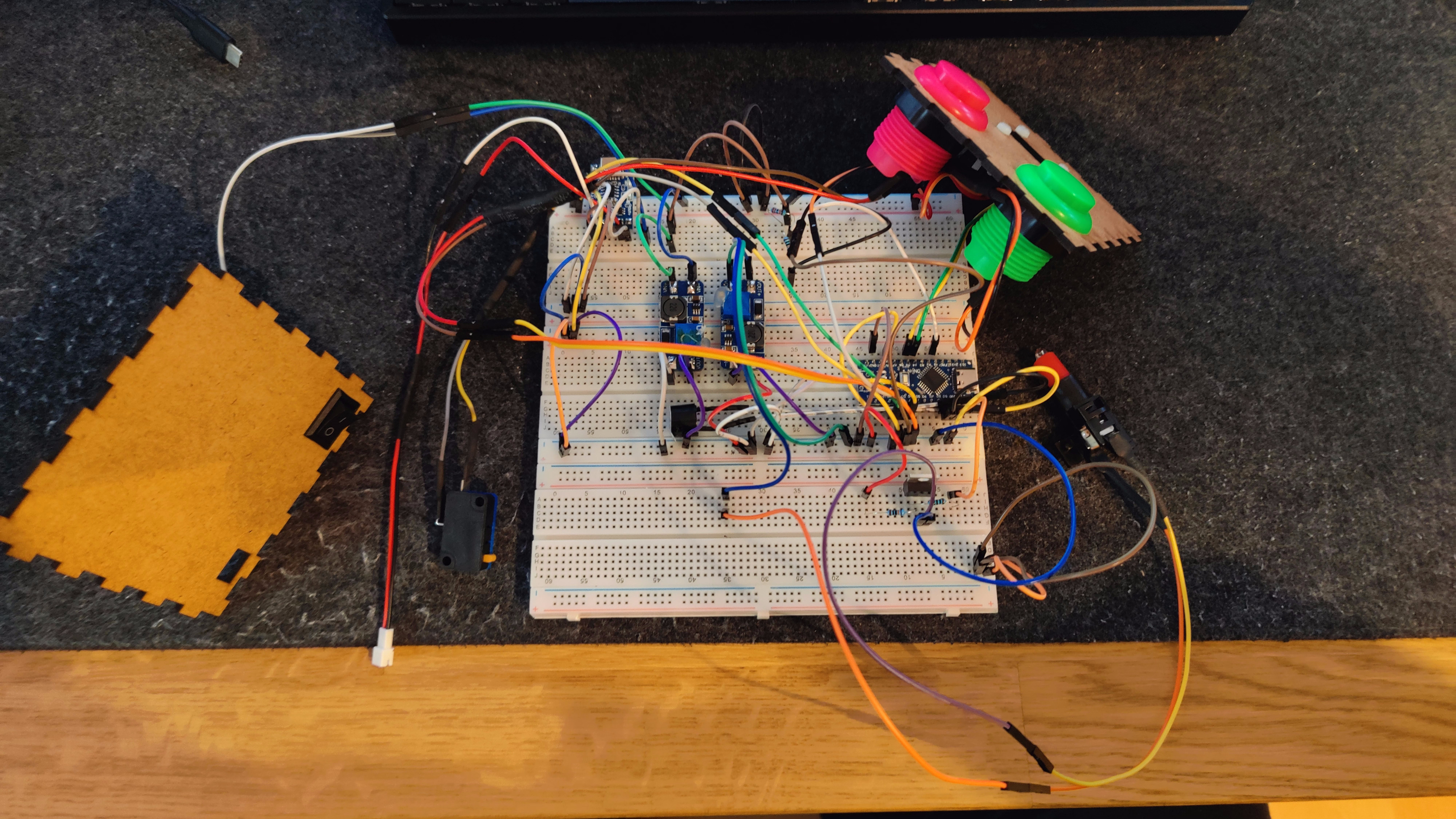
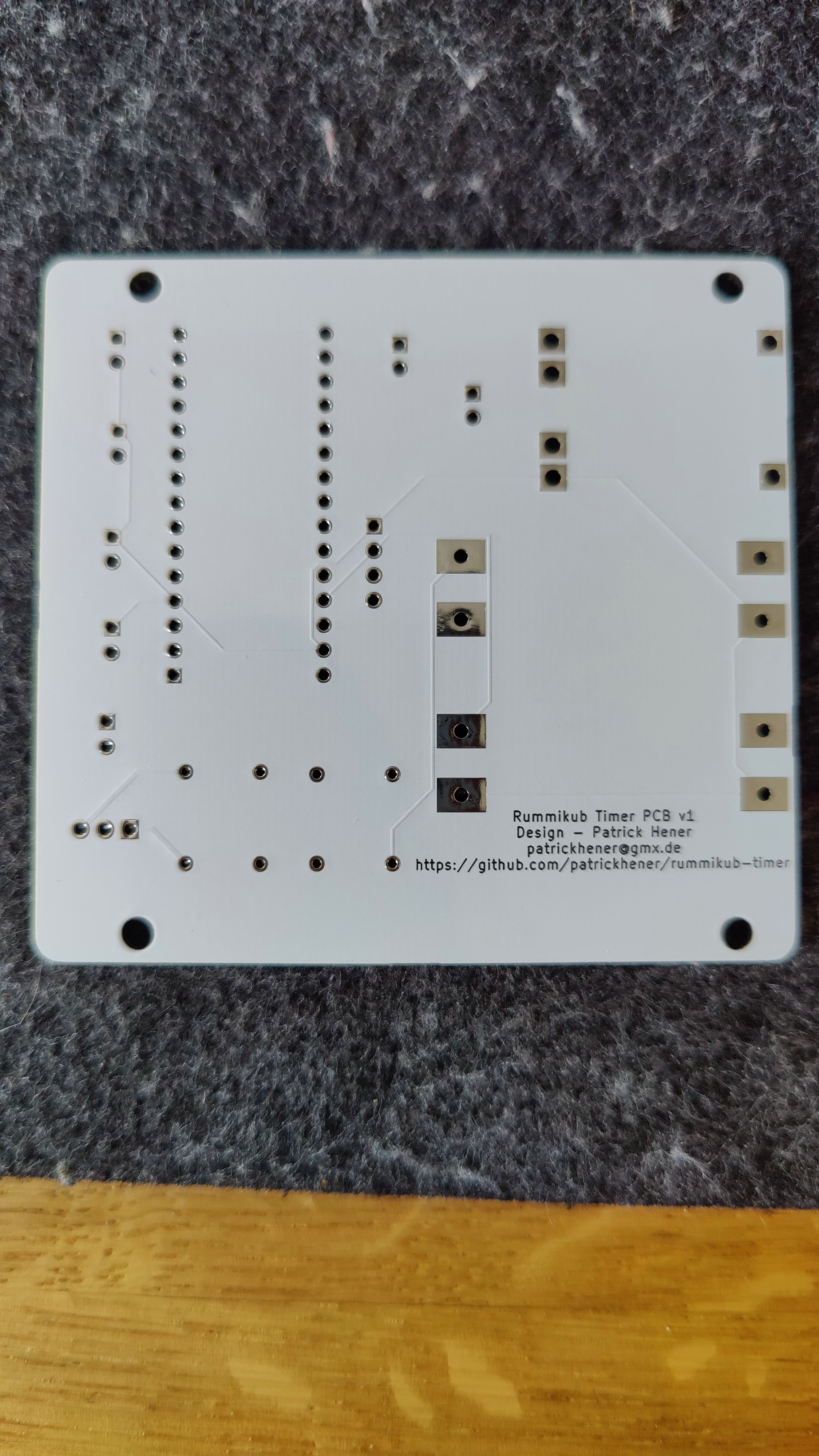
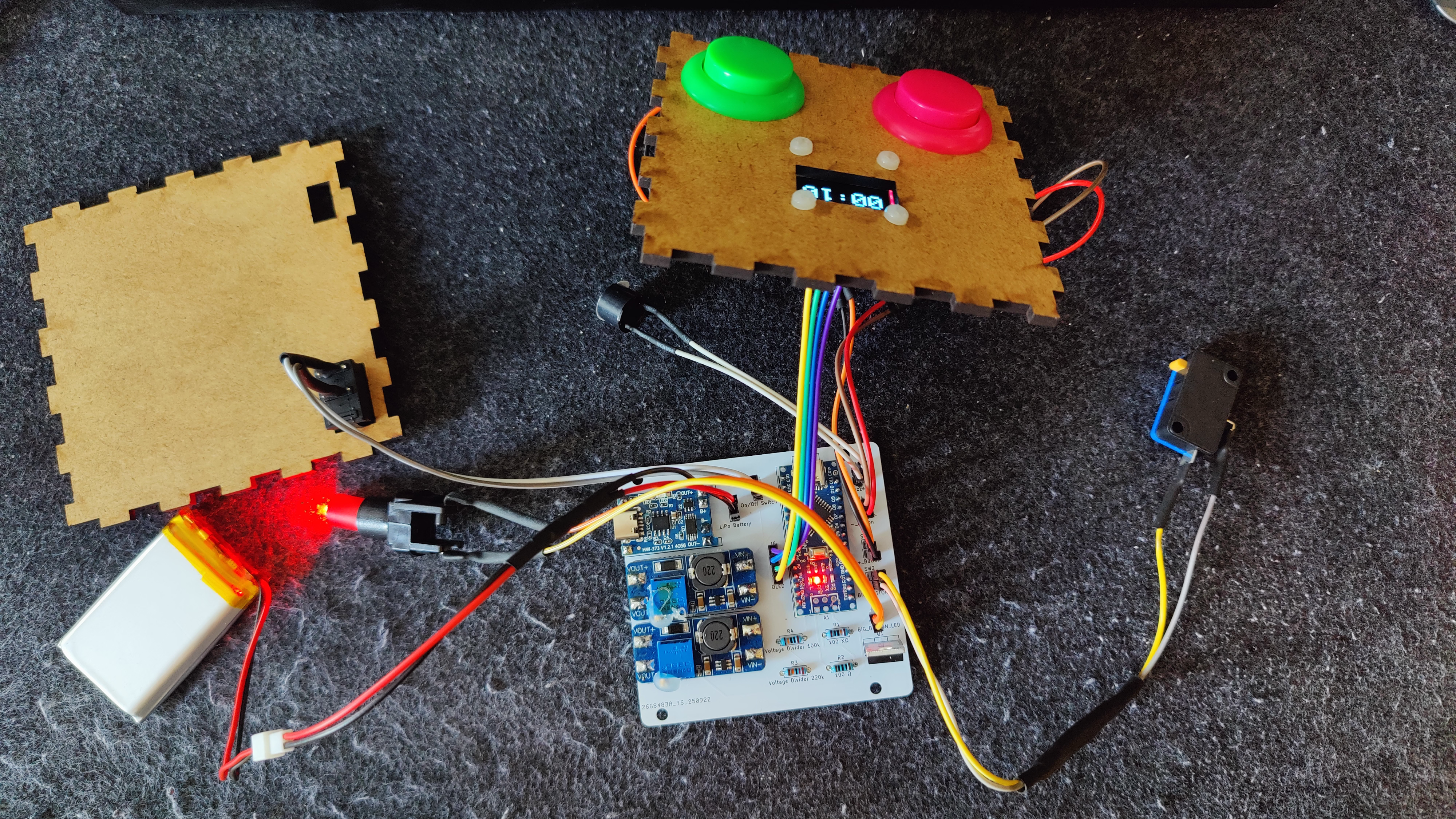
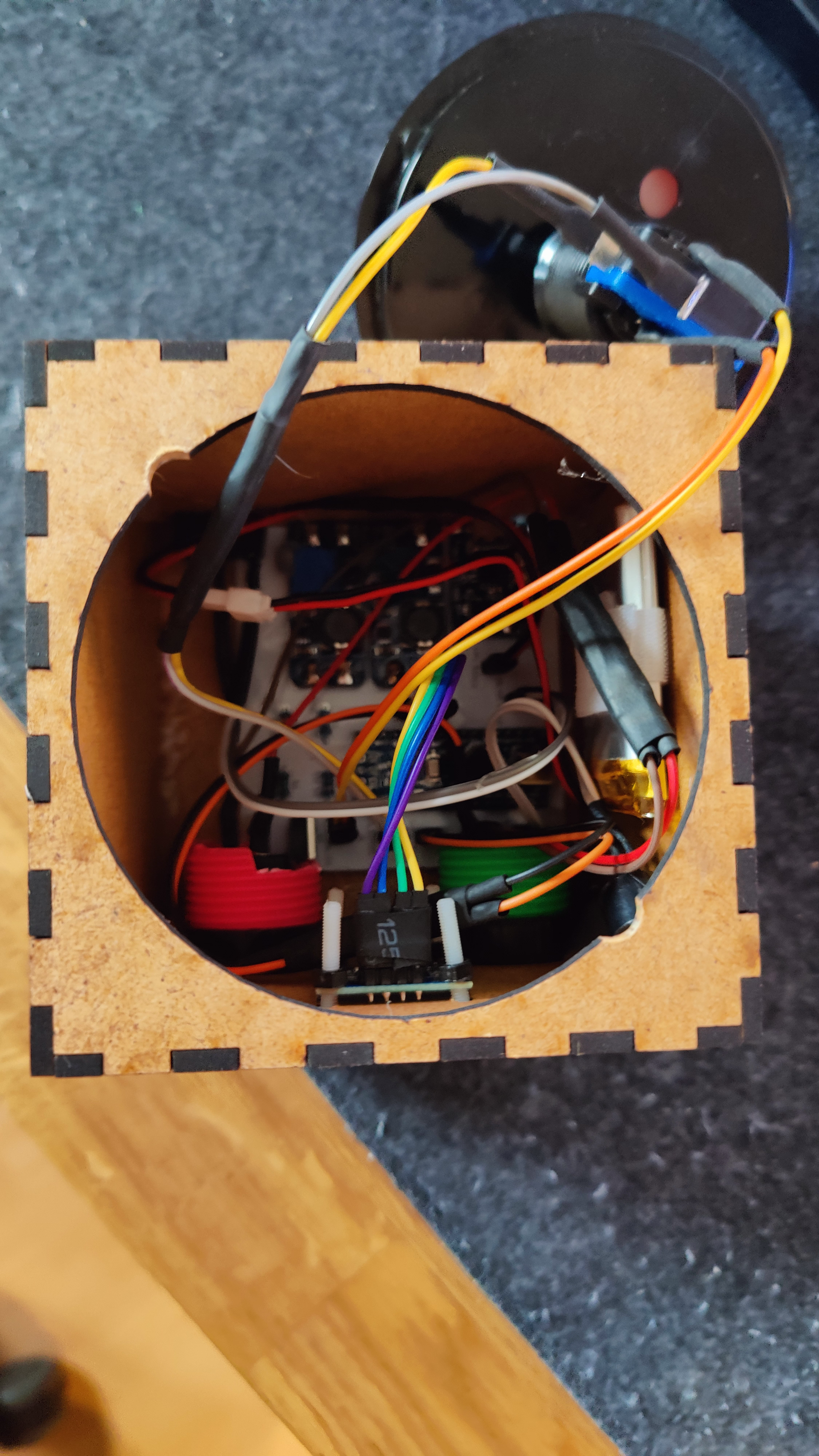
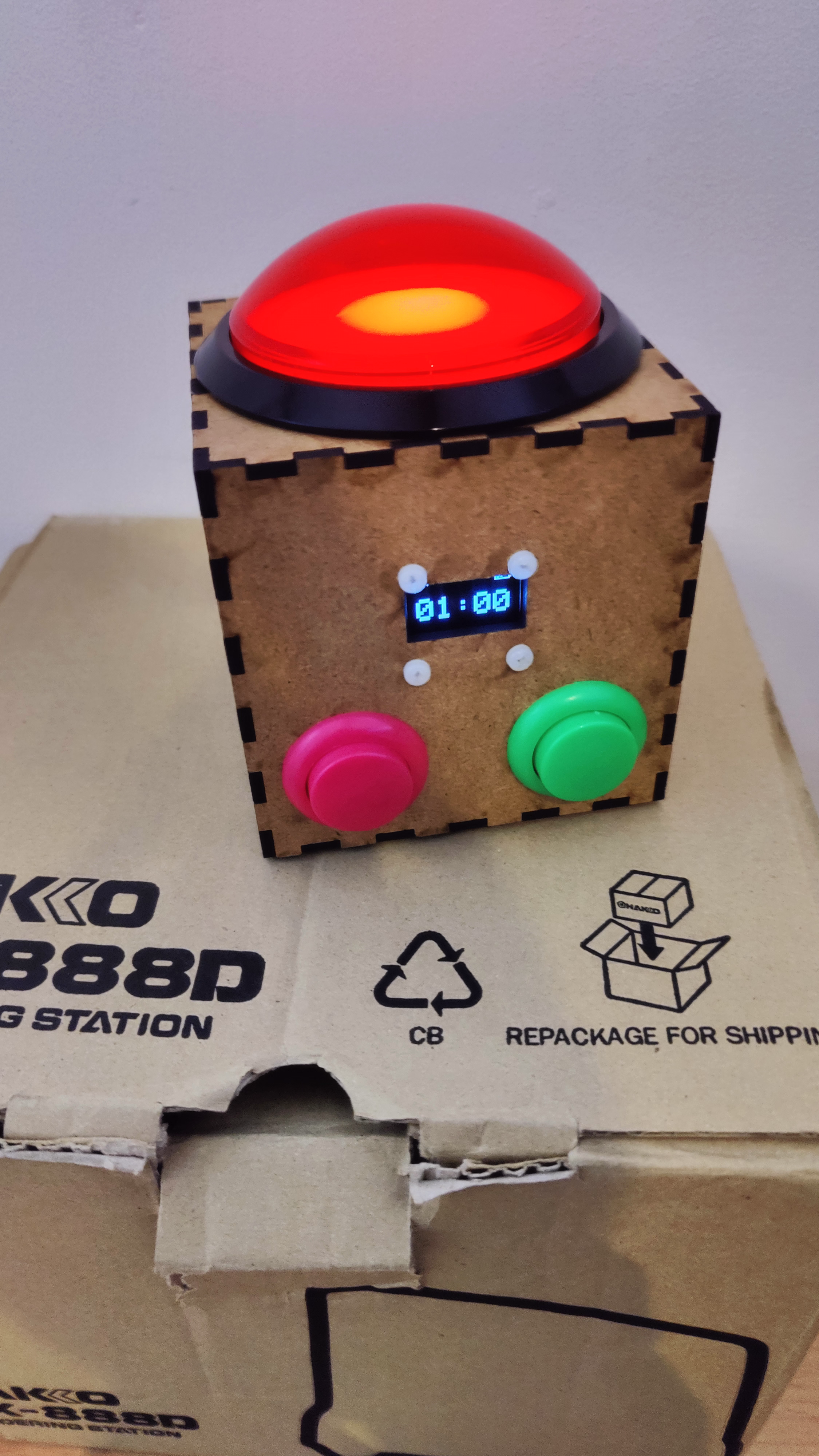
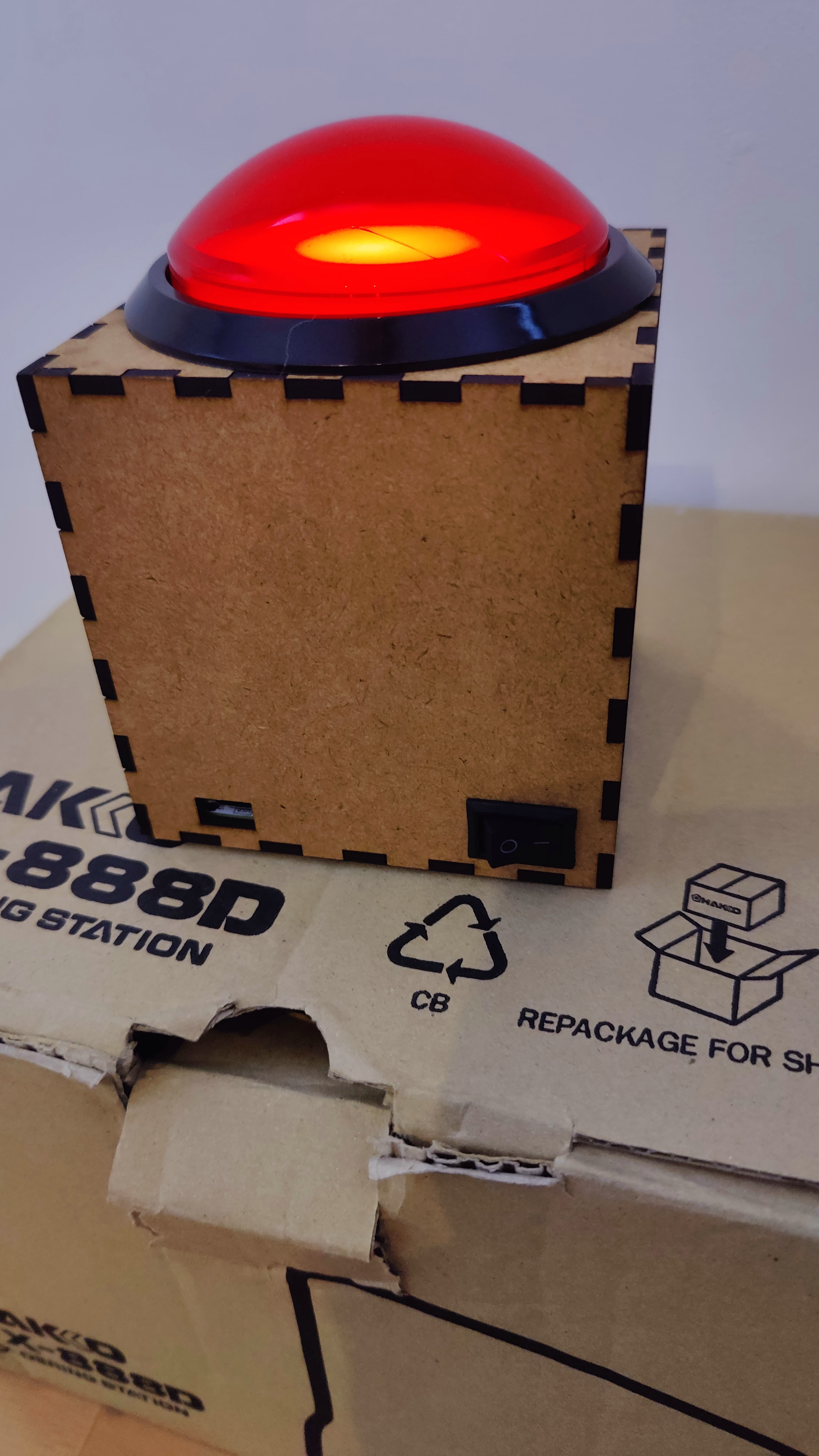
The box is really tight, so I had to improvise and cut away from some of the buttons. Also The top button is not fixed into casing as it is to tight. But that in fact is better, so you can assamble and then maintaine it, by just pulling the big button out. As the button will be pushed it is not a problem it is not fixed anyways.
If you build it like I did never run and charge at the same time. The missing safe charge circuit during load is not sharing the load, so the battery will be over-charged and might caught on fire. I DO NOT HOLD ACCOUNTABILITY FOR DAMAGE TO YOU OR YOUR SURROUNDINGS.
| Qty | Value | Footprint | References |
|---|---|---|---|
| 1 | +_Button | Connector_PinHeader_2.54mm:PinHeader_1x02_P2.54mm_Vertical | SW3 |
| 1 | -_Button | Connector_PinHeader_2.54mm:PinHeader_1x02_P2.54mm_Vertical | SW4 |
| 1 | 100 KΩ | Resistor_THT:R_Axial_DIN0207_L6.3mm_D2.5mm_P7.62mm_Horizontal | R1 |
| 1 | 100 Ω | Resistor_THT:R_Axial_DIN0207_L6.3mm_D2.5mm_P7.62mm_Horizontal | R2 |
| 1 | 12V Booster | Rummikub-Timer:MT3608_module | J4 |
| 1 | 5V Booster | Rummikub-Timer:MT3608_module | J3 |
| 1 | Arduino_Nano_v3.x | Module:Arduino_Nano | A1 |
| 1 | BIG_BUTTON | Connector_PinHeader_2.54mm:PinHeader_1x02_P2.54mm_Vertical | SW2 |
| 1 | BIG_BUTTON_LED | Connector_PinHeader_2.54mm:PinHeader_1x02_P2.54mm_Vertical | J5 |
| 1 | Buzzer | Connector_PinHeader_2.54mm:PinHeader_1x02_P2.54mm_Vertical | BZ1 |
| 1 | IRLZ44N | Package_TO_SOT_THT:TO-220-3_Vertical | Q1 |
| 1 | LiPo Battery | Connector_PinHeader_2.54mm:PinHeader_1x02_P2.54mm_Vertical | J1 |
| 1 | OLED | Connector_PinHeader_2.54mm:PinHeader_1x04_P2.54mm_Vertical | J6 |
| 1 | On/Off Switch | Connector_PinHeader_2.54mm:PinHeader_1x02_P2.54mm_Vertical | SW1 |
| 1 | TP4046 Charger Type-C | Rummikub-Timer:TP4056-18650 | J2 |
| 1 | Voltage Divider 100k | Resistor_THT:R_Axial_DIN0207_L6.3mm_D2.5mm_P7.62mm_Horizontal | R4 |
| 1 | Voltage Divider 220k | Resistor_THT:R_Axial_DIN0207_L6.3mm_D2.5mm_P7.62mm_Horizontal | R3 |
It measures 77.5 × 72.9 mm and has 2 copper layers, 1.6 mm thick.
17 parts, built around the IRLZ44N. The full list of its parts is on this page, with links to each part's symbol and footprint where PCBKit's library has them.
From the patrickhener/rummikub-timer repository on GitHub, at the commit this page was made from: the board is schema/Rummikub_Timer.kicad_pcb and its schematic schema/Rummikub_Timer.kicad_sch. PCBKit opens the board in the browser, with nothing to install.
Its repository states no licence, so its author keeps all rights: ask patrickhener before reusing the design.


pscrespo/Morpheus-STM32
A small 3D printer controller board for use with a "blue pill" STM32F1 generic board. Inspired on http://reprap.org/wiki/SinapTec


MitchBradley/Esp32PrinterController
PCB design for 3D printer controller using ESP32 processor


robinolejnik/dmx-ledstrip-dimmer-32ch
Arduino Mini and TLC5940 based 32 channel 12V PWM dimmer with DMX512 and RDM support.

Moragor/BatteryAnalyzer_MkII
Updated Version of the battery analyzer, now with constant current