

2 layers100 × 100 mm
V2.2 Mechanical Seven Segment Controller
OverInvented/Flippy
The code needed to build a mechanical 7-segment display that uses electromagnets to display characters
53 parts65
 patrick3making/thermometer-shield
KiCad project for sensors, display, and control outputs to facilitate environment based automation.
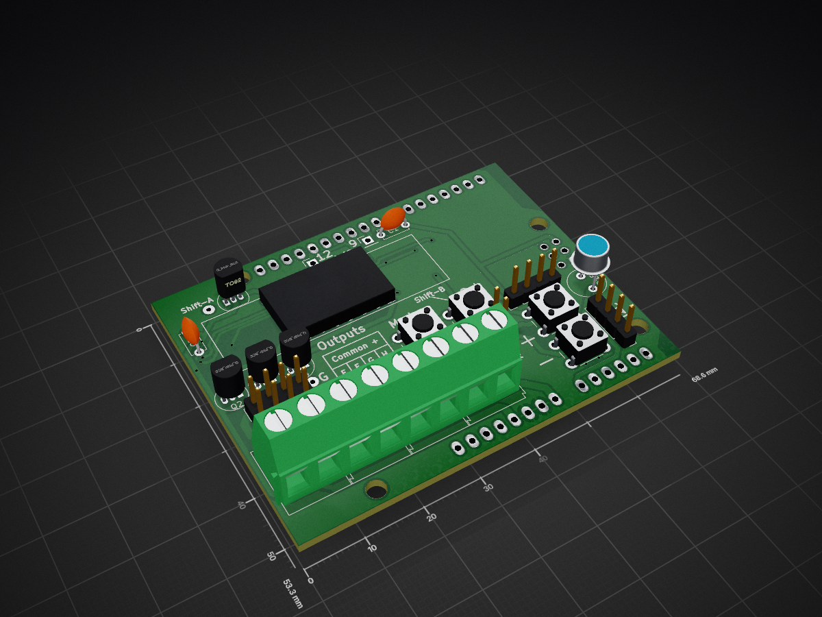
Thermometer shield is an open-source printed circuit board by patrick3making, from the patrick3making/thermometer-shield repository on GitHub. It is a 2-layer board with 51 parts on 66 nets, routed with 463 tracks and 18 vias.
It is built around the 74HC595 and ULN2803A. Its parts include 22 resistors, 14 connectors, 4 transistors, 4 switches and 3 ICs. It belongs with the sensors and measurement boards of this library.
I wanted a display of temperature and humidity and it exploded into this shield that functions as a thermostat, humidistat, and optostat (if that's even a word). This project is my first attempt at creating a pcb. The design work is done in KiCAD.
See the PDF for the full shcematic and the SVGs for the inverted copper etching masks.
There was more to this list that I think I forgot about, but these are the high points.
| Qty | Value | Footprint | References |
|---|---|---|---|
| 10 | 330 | Resistors_SMD:R_0603_HandSoldering | R5, R6, R7, R8, R9, R10, R11, R12, R13, R14 |
| 7 | 2K2 | Resistors_SMD:R_0805_HandSoldering | R16, R17, R18, R19, R20, R21, R22 |
| 4 | Q_PNP_BCE | TO_SOT_Packages_THT:TO-92_Inline_Narrow_Oval | Q1, Q2, Q3, Q4 |
| 4 | R | Resistors_SMD:R_0805_HandSoldering | R1, R2, R3, R4 |
| 4 | SW_SPST | Buttons_Switches_THT:SW_PUSH_6mm | SW1, SW2, SW3, SW4 |
| 2 | 74HC595 | Housings_SSOP:TSSOP-16_4.4x5mm_Pitch0.65mm | U1, U2 |
| 2 | C | Capacitors_THT:C_Disc_D5.0mm_W2.5mm_P5.00mm | C1, C2 |
| 1 | 4x7Seg | SparkFun:ATA3492 | Disp1 |
| 1 | A1050 | Opto-Devices:Resistor_LDR_D6.4_RM3.4 | R15 |
| 1 | ARDUINO_SHIELD | Arduino_Shield:ARDUINO_SHIELD | SHIELD1 |
| 1 | Analog | Pin_Headers:Pin_Header_Straight_1x02_Pitch2.54mm | J4 |
| 1 | I2C | Pin_Headers:Pin_Header_Straight_1x04_Pitch2.54mm | J5 |
| 1 | Out-A | Connectors:AK300-2 | J10 |
| 1 | Out-B | Connectors:AK300-2 | J11 |
| 1 | Out-C | Connectors:AK300-2 | J12 |
| 1 | Out-D | Connectors:AK300-2 | J13 |
| 1 | Outputs | Pin_Headers:Pin_Header_Straight_2x04_Pitch2.54mm | J9 |
| 1 | Pin12 | Pin_Headers:Pin_Header_Straight_1x01_Pitch2.54mm | J14 |
| 1 | Pin9 | Pin_Headers:Pin_Header_Straight_1x01_Pitch2.54mm | J6 |
| 1 | Shift-A | Wire_Pads:SolderWirePad_single_0-8mmDrill | J2 |
| 1 | Shift-B | Wire_Pads:SolderWirePad_single_0-8mmDrill | J3 |
| 1 | TempSensor | Pin_Headers:Pin_Header_Straight_1x04_Pitch2.54mm | J1 |
| 1 | Trig-G | Wire_Pads:SolderWirePad_single_0-8mmDrill | J7 |
| 1 | Trig-H | Wire_Pads:SolderWirePad_single_0-8mmDrill | J8 |
| 1 | ULN2803A | Housings_SOIC:SOIC-18W_7.5x11.6mm_Pitch1.27mm | U3 |
51 parts, built around the 74HC595 and ULN2803A. The full list of its parts is on this page, with links to each part's symbol and footprint where PCBKit's library has them.
From the patrick3making/thermometer-shield repository on GitHub, at the commit this page was made from: the board is Thermometer-Shield.kicad_pcb. PCBKit opens the board in the browser, with nothing to install.
Its repository states no licence, so its author keeps all rights: ask patrick3making before reusing the design.
OverInvented/Flippy
The code needed to build a mechanical 7-segment display that uses electromagnets to display characters


niteshkadyan/Hearty-LED-Necklace-Badge
Kicad project files and Android app for the Hearty LED wearable necklace cum badge

julianschick/flipdot-brose
Microcontroller code (ESP32) and Circuit Design for controlling Brose Flipdot Modules.

LudovicLemarinel/EspHomeAutomation
Home Automation based on ESP8266 and MQTT
