2 layers20.5 × 24.8 mm

 Parathova/stepper-motor-controller-pcb
Designed a custom PCB in KiCad to control a NEMA-17 stepper motor through an A4988 driver.
SteppperMotorPCB is an open-source printed circuit board by Parathova, from the Parathova/stepper-motor-controller-pcb repository on GitHub. It is a 2-layer board of 50.5 × 46 mm with 8 parts on 25 nets, routed with 33 tracks and 0 vias.
Its parts include 4 connectors, 2 switches and 1 capacitor.
Designed a custom PCB in KiCad to control a NEMA-17 stepper motor through an A4988 driver.
The design includes:
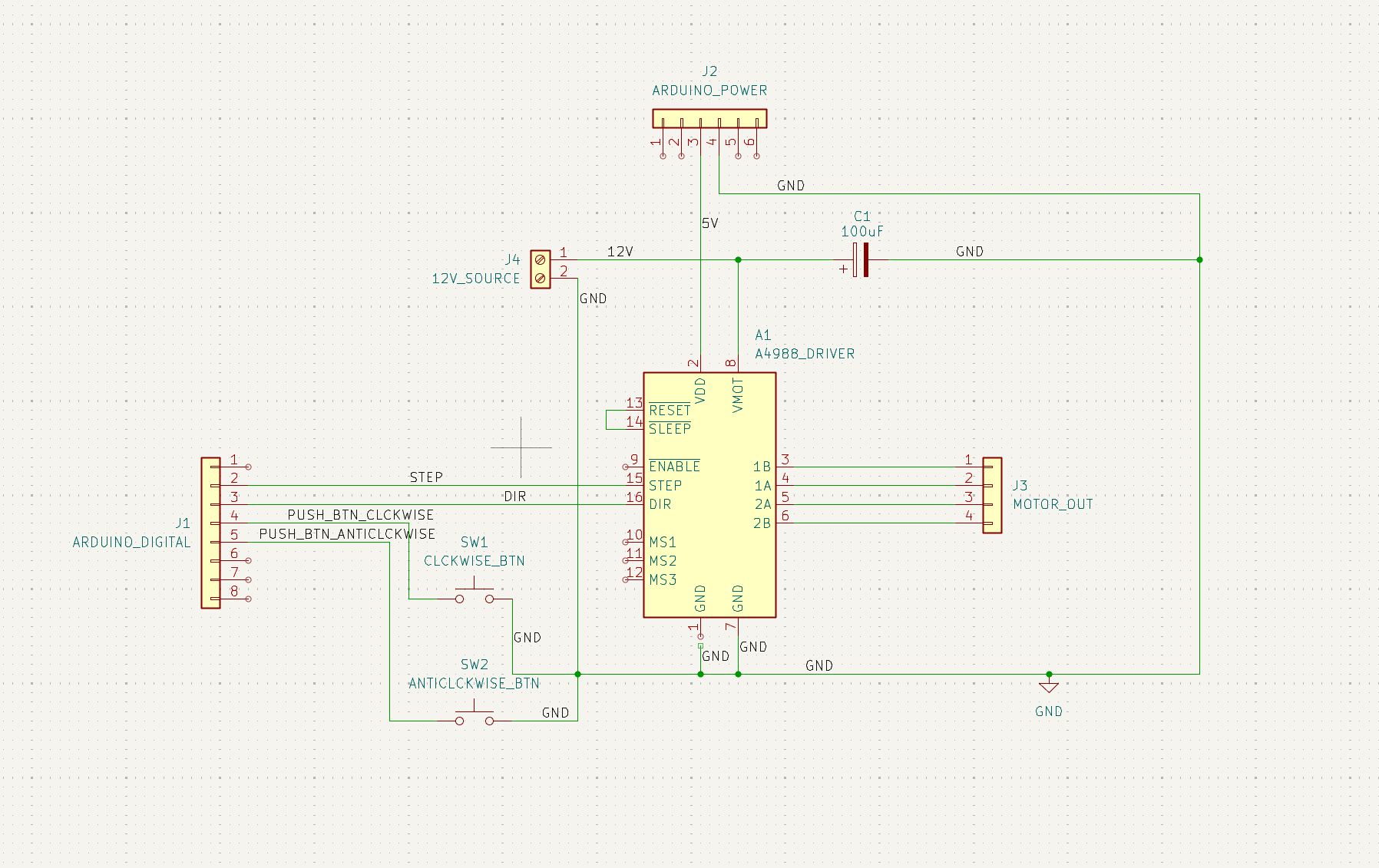
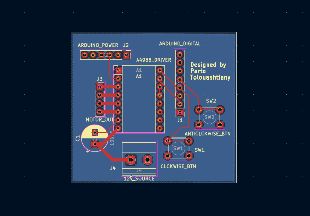
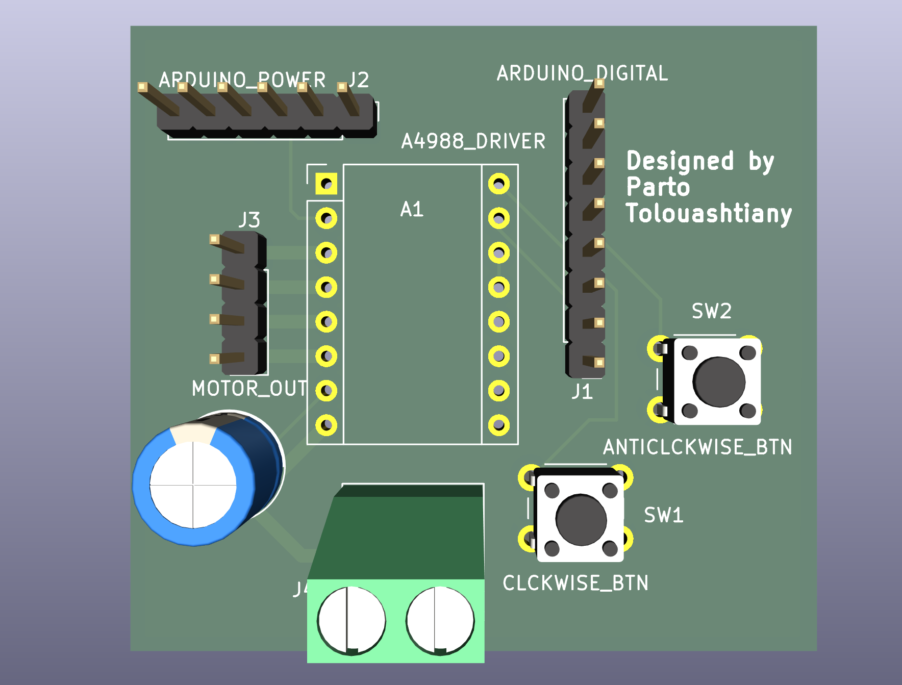
| Qty | Value | Footprint | References |
|---|---|---|---|
| 1 | 100uF | Capacitor_THT:CP_Radial_D8.0mm_P3.50mm | C1 |
| 1 | 12V_SOURCE | TerminalBlock_Phoenix:TerminalBlock_Phoenix_MKDS-1,5-2-5.08_1x02_P5.08mm_Horizontal | J4 |
| 1 | A4988_DRIVER | Module:Pololu_Breakout-16_15.2x20.3mm | A1 |
| 1 | ANTICLCKWISE_BTN | Button_Switch_THT:SW_PUSH_6mm | SW2 |
| 1 | ARDUINO_DIGITAL | Connector_PinHeader_2.54mm:PinHeader_1x08_P2.54mm_Vertical | J1 |
| 1 | ARDUINO_POWER | Connector_PinHeader_2.54mm:PinHeader_1x06_P2.54mm_Vertical | J2 |
| 1 | CLCKWISE_BTN | Button_Switch_THT:SW_PUSH_6mm | SW1 |
| 1 | MOTOR_OUT | Connector_PinHeader_2.54mm:PinHeader_1x04_P2.54mm_Vertical | J3 |

joeycastillo/Sensor-Watch
A board replacement for the classic Casio F-91W wristwatch

rusefi/rusefi
rusefi - GPL internal combustion engine control unit

hoglet67/RGBtoHDMI
Bare-metal Raspberry Pi project that provides pixel-perfect sampling of Retro Computer RGB/YUV video and conversion to HDMI

shanteacontrols/OpenDeck
A platform for building interactive control and sensing devices using MIDI and OSC built with Zephyr RTOS.

hackclub/OnBoard
💡 Join 1,000 teenagers and make your first PCB with a $100 grant!

dangiu/PicoMemcard
Emulating PSX Memory Card (or controller) using a Raspberry Pi Pico

OLIMEX/DIY-LAPTOP
Do It Yourself Open Source Hardware and Software Modular Hacker's Friendly Laptop
It measures 50.5 × 46 mm and has 2 copper layers, 1.6 mm thick.
8 parts. The full list of its parts is on this page, with links to each part's symbol and footprint where PCBKit's library has them.
From the Parathova/stepper-motor-controller-pcb repository on GitHub, at the commit this page was made from: the board is SteppperMotorPCB.kicad_pcb and its schematic SteppperMotorPCB.kicad_sch. PCBKit opens the board in the browser, with nothing to install.
Its repository states no licence, so its author keeps all rights: ask Parathova before reusing the design.