Skip to the content
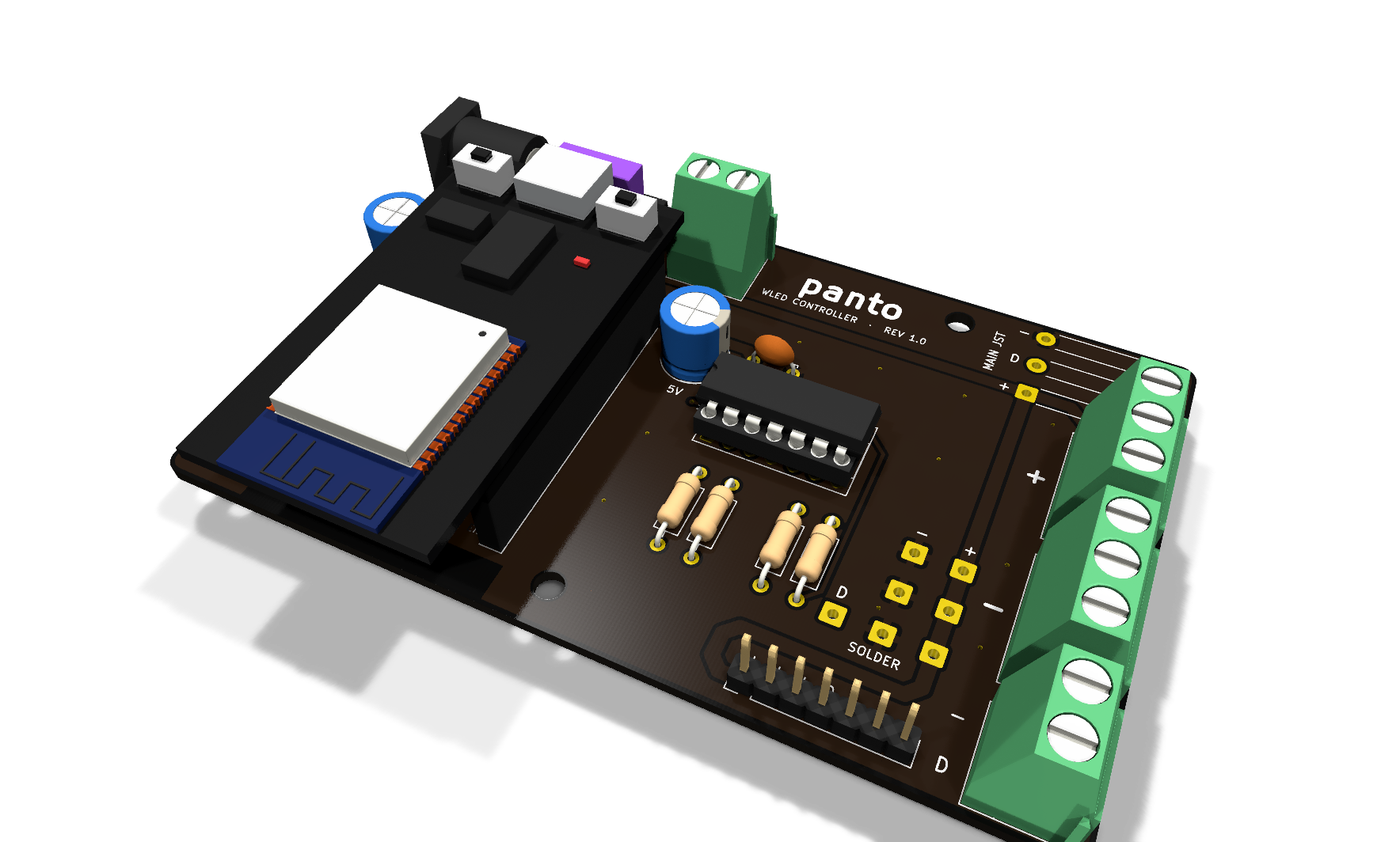
2 layers100 × 61.8 mmWled controller v2-phi, the printed circuit board in 3D

Wled controller v2-phi

PantoYT/wled-controller

Script-generated KiCad carrier boards for an ESP32 running WLED (1 and 6 channels), a custom A* router, and 3D-printed mounts checked for collisions against the board models

Size
100 × 61.8 mm
Copper layers
2
Thickness
1.6 mm
Parts
37
Nets
28
Pads
128
Tracks, vias
143, 24
Pours
3
Routed
Yes
KiCad
KiCad 10.0 (file 20260206)
Created
20 Oct 2026
Updated
29 Oct 2026

Overview

Wled controller v2-phi is an open-source printed circuit board by PantoYT, from the PantoYT/wled-controller repository on GitHub, published under the MIT licence. It is a 2-layer board of 100 × 61.8 mm with 37 parts on 28 nets, routed with 143 tracks and 24 vias.

It is built around the 74HCT245. Its parts include 14 connectors, 7 fuses, 6 resistors, 3 capacitors and 3 ICs. It belongs with the computers and single-board computers boards and the ESP32 boards of this library.

Main components

1

README

rev1/README.md

wled-controller rev 1.0 (built, on the desk)

A 100 × 61.8 mm (golden rectangle) two-layer carrier board for an ESP32 DevKit (30-pin) running WLED with 5 V addressable LED strips (WS2812B and similar). It follows the classic WLED wiring diagram by @DedeHai: fused 5 V input, bulk capacitors on 5 V and 3.3 V, a 74AHCT125 level shifter and series data resistors.

3D view

Prices and where to buy: BOM.md. Rev 2.0: ../rev2/. Enclosure and desk base: ../enclosure/rev1/.

What is on the board

  • Power input (all in parallel, before the fuse; use one at a time): DC jack 5.5/2.1 mm, 2-pin screw terminal, solder pads, 2-pin header (max 3 A).
  • F1: mini blade fuse, sized to the power supply (3 A for a 5 V / 3 A PSU).
  • ESP32 DevKit in two 1×15 female headers, 25.4 mm row spacing, USB-C facing the top edge, 3V3 capacitor on the left, VIN capacitor on the right.
  • U1 74AHCT125: GPIO4 (D4) drives all four buffers, and each has its own series resistor:
    • MAIN: solder pads with strain relief for a JST SM pigtail (+, D, −)
    • SCREW: separate blocks on the right edge: 3× +, 3× −, and a D + − pair
    • SOLDER: D, 3× −, 3× +
    • PINS: 7-pin header + + + D − − −
  • Back silkscreen: "panto" (optional pixel-art outline with --gear path.png).
  • GND pours on both layers and a copper keepout under the ESP32 antenna.

Bill of materials

RefPartQty
U1SN74AHCT125N (DIP-14). Must be AHCT or HCT, plain HC will not work1
—DIP-14 socket1
U2, U3Female header 1×15, 2.54 mm2
C1, C21000 µF 16 V electrolytic, Ø8 mm, 5 mm pitch2
C3100 nF ceramic (MLCC), 5 mm pitch1
R1–R4100 Ω 0.25 W axial (33–200 Ω works)4
F1Mini blade fuse holder, Keystone 3568 footprint, plus 3 A mini blade fuse1
J1DC barrel jack 5.5/2.1 mm, PCB mount (DC-005 style)1
J2, J6–J8Screw terminals 5.08 mm: 2× 3-pole, 2× 2-pole4
J4, J12Male pin header 1×2 and 1×71 each
J5JST SM 3-pin pigtail (female side soldered into the board)1
H1–H4M3 standoffs (optional)4

Regenerating

gen_board.py builds the unrouted board with KiCad's bundled Python:

text
"C:/Program Files/KiCad/10.0/bin/python.exe" gen_board.py --gear path/to/gear.png

It overwrites wled-controller.kicad_pcb, so do not run it after routing has started. Set KICAD10_FOOTPRINT_DIR if KiCad is installed somewhere else.

3D model

The 3D view shows the chip in its socket, a 3 A fuse and a stand-in ESP32 DevKit (KiCad's WROOM-32 model on simple boxes from ../3d/make_boxes.py). The stand-in is the ESP1 footprint: board-only, no pads, excluded from BOM and position files. gen_board.py --mask Purple changes the solder mask colour used by the 3D view.

Routing

route.py is a small grid A* router (numpy, KiCad's bundled Python). It routes every net except GND, which the pours on both layers pick up, then adds GND stitching vias:

text
cp wled-controller.unrouted.kicad_pcb wled-controller.kicad_pcb
"C:/Program Files/KiCad/10.0/bin/python.exe" route.py
kicad-cli pcb drc --refill-zones --save-board wled-controller.kicad_pcb

Power nets are 1.5 mm (VIN_RAW, +5V) and 1.0 mm (+3V3), signals 0.4 mm. wled-controller-gerbers.zip holds the Gerbers and drill file for the fab.

Before ordering

  • Measure your ESP32's row spacing and compare the pin labels on the silkscreen with your board. ESP_ROW_SPACING in the script sets the spacing.
  • Import wled-controller.step into your CAD tool to design an enclosure around it.
  • Check the polarity of the DC plug with a multimeter. The board expects centre positive.
  • In WLED, set the LED output to GPIO4 and cap the current limit at about 2500 mA for a 3 A supply.

Rev 1.0 build notes (2026-10-14)

Board #1 was hand-soldered and drives a strip without flicker. Problems found on the way, as input for v2:

  • Fuse holder under the ESP32. The KEYS3568 holder sits under the overhanging end of the DevKit, so the ESP32 needs a second layer of female headers to clear it. The extra contact made VIN unreliable (the board only worked while the ESP32 was pushed sideways); bending the extra header's VIN leg slightly fixed it. v2: every tall part outside the ESP32 outline, one contact between module and board.
  • Cold joints on the power pins. The first pads of both header rows (3V3, VIN, GND) sit on wide power traces and pour; at normal iron temperature the solder did not wet. v2: thermal reliefs on those pads, or solder them at 360-370 °C.
  • White solder mask shows flux residue and turns yellow around joints. Pick black or green.
  • Lead time. A month of waiting for one board order; order at least 2-3 sets of every part, and more than one board revision in the same order when possible.
  • Strip cable. The board should not hang behind the desk: add a 0.5 m JST SM 3-pin extension.

v2 ideas

  • at least 4 independent outputs (separate GPIOs, not copies of one signal), possibly room for two ESP32 boards;
  • fuse moved away from the module, ideally a main fuse plus protection per output;
  • connectors that do not need hand-made pigtails.

Parts

37
QtyValueFootprintReferences
6100RResistor_THT:R_Axial_DIN0207_L6.3mm_D2.5mm_P2.54mm_VerticalR1, R2, R3, R4, R5, R6
6MF-RG300 3AFuse:Fuse_Bourns_MF-RG300F11, F12, F13, F14, F15, F16
3M3MountingHole:MountingHole_3.2mm_M3H1, H2, H3
21000uF 16VCapacitor_THT:CP_Radial_D8.0mm_P5.00mmC1, C2
2ESP32 socketConnector_PinSocket_2.54mm:PinSocket_1x15_P2.54mm_VerticalU2, U3
1100nFCapacitor_THT:C_Disc_D5.0mm_W2.5mm_P5.00mmC3
174HCT245Package_DIP:DIP-20_W7.62mm_SocketU1
1ESP32 DevKit (3D only)ESP1
1JST-XH CH1Connector_JST:JST_XH_B3B-XH-A_1x03_P2.50mm_VerticalJ21
1JST-XH CH2Connector_JST:JST_XH_B3B-XH-A_1x03_P2.50mm_VerticalJ22
1JST-XH CH3Connector_JST:JST_XH_B3B-XH-A_1x03_P2.50mm_VerticalJ23
1JST-XH CH4Connector_JST:JST_XH_B3B-XH-A_1x03_P2.50mm_VerticalJ24
1JST-XH CH5Connector_JST:JST_XH_B3B-XH-A_1x03_P2.50mm_VerticalJ25
1JST-XH CH6Connector_JST:JST_XH_B3B-XH-A_1x03_P2.50mm_VerticalJ26
1Mini blade fuse, 7.5 A maxFuse:Fuseholder_Blade_Mini_Keystone_3568F1
1PC-GK2.1wled:DC_Jack_Ninigi_PC-GK2.1J1
1Screw 2p INTerminalBlock_Phoenix:TerminalBlock_Phoenix_MKDS-1,5-2-5.08_1x02_P5.08mm_HorizontalJ2
1Screw CH1TerminalBlock_Phoenix:TerminalBlock_Phoenix_PT-1,5-3-3.5-H_1x03_P3.50mm_HorizontalJ11
1Screw CH2TerminalBlock_Phoenix:TerminalBlock_Phoenix_PT-1,5-3-3.5-H_1x03_P3.50mm_HorizontalJ12
1Screw CH3TerminalBlock_Phoenix:TerminalBlock_Phoenix_PT-1,5-3-3.5-H_1x03_P3.50mm_HorizontalJ13
1Screw CH4TerminalBlock_Phoenix:TerminalBlock_Phoenix_PT-1,5-3-3.5-H_1x03_P3.50mm_HorizontalJ14
1Screw CH5TerminalBlock_Phoenix:TerminalBlock_Phoenix_PT-1,5-3-3.5-H_1x03_P3.50mm_HorizontalJ15
1Screw CH6TerminalBlock_Phoenix:TerminalBlock_Phoenix_PT-1,5-3-3.5-H_1x03_P3.50mm_HorizontalJ16

More from PantoYT/wled-controller

4
  • 2 layers120 × 74.2 mmWled controller v2-120, the printed circuit board in 3D

    Wled controller v2-120

    PantoYT/wled-controller

    Script-generated KiCad carrier boards for an ESP32 running WLED (1 and 6 channels), a custom A* router, and 3D-printed mounts checked for collisions against the board models

    45 partsMIT
  • 2 layers100 × 61.8 mmWled controller v2-phi4, the printed circuit board in 3D

    Wled controller v2-phi4

    PantoYT/wled-controller

    Script-generated KiCad carrier boards for an ESP32 running WLED (1 and 6 channels), a custom A* router, and 3D-printed mounts checked for collisions against the board models

    41 partsMIT
  • 2 layers100 × 61.8 mmWled controller v2-wall, the printed circuit board in 3D

    Wled controller v2-wall

    PantoYT/wled-controller

    Script-generated KiCad carrier boards for an ESP32 running WLED (1 and 6 channels), a custom A* router, and 3D-printed mounts checked for collisions against the board models

    32 partsMIT
  • 2 layers100 × 61.8 mmWled controller.unrouted, the printed circuit board in 3D

    Wled controller.unrouted

    PantoYT/wled-controller

    Script-generated KiCad carrier boards for an ESP32 running WLED (1 and 6 channels), a custom A* router, and 3D-printed mounts checked for collisions against the board models

    31 partsMIT

Similar boards

  • 2 layers297.2 × 180.3 mm8bit computer, the printed circuit board in 3D

    8bit computer

    vascofazza/8bit-cpu

    Schematics & code for my 74LS-based 8-bit MK1 CPU

    377 parts317MIT
  • 4 layers304.8 × 330.2 mm2000ATX, the printed circuit board in 3D

    2000ATX

    jasonsbeer/Amiga-2000-EATX

    An Amiga 2000 PCB in the EATX form factor.

    614 parts200GPL-3.0
  • 2 layers138 × 96.9 mmISA Card, the printed circuit board in 3D

    ISA Card

    AkBKukU/CM153-Repro

    A reproduction of the Philips CM-153 LMSI controller

    161 parts145
  • 2 layers237.7 × 146.1 mmTipi peb, the printed circuit board in 3D

    Tipi peb

    jedimatt42/tipi

    TI-99/4A to Raspberry PI messaging through console sideport

    51 parts77
  • 4 layers318.4 × 124.5 mmN2360, the printed circuit board in 3D

    N2360

    jasonsbeer/Amiga-N2630

    A re-imagining of the Amiga A2630 processor card.

    248 parts69
  • 4 layers292.1 × 88.3 mmSnark barker mca, the printed circuit board in 3D

    Snark barker mca

    schlae/snark-barker-mca

    A Sound Blaster compatible sound card for Micro Channel bus computers

    177 parts69
  • 2 layers216 × 150 mmMotherboard-101, the printed circuit board in 3D

    Motherboard-101

    artemisamsx/artemisa

    Schematics, PCB designs and HDL simulations to build a 8-bits MSX computer

    124 parts67
  • 2 layers100 × 66.1 mmPicoWiFiModem, the printed circuit board in 3D

    PicoWiFiModem

    mecparts/PicoWiFiModem

    A Pico W based RS232 <-> WiFi modem with Hayes AT style commands and LED indicators

    39 parts64GPL-3.0

Questions

How big is the Wled controller v2-phi PCB?

It measures 100 × 61.8 mm and has 2 copper layers, 1.6 mm thick.

What parts does the Wled controller v2-phi use?

37 parts, built around the 74HCT245. The full list of its parts is on this page, with links to each part's symbol and footprint where PCBKit's library has them.

Where can I download the Wled controller v2-phi KiCad files?

From the PantoYT/wled-controller repository on GitHub, at the commit this page was made from: the board is rev2/old-variants/wled-controller-v2-phi.kicad_pcb. PCBKit opens the board in the browser, with nothing to install.

Can I use the Wled controller v2-phi design in my own project?

Its repository publishes it under the MIT licence: you may reuse it on that licence's terms (keep the author's notice, and for a copyleft licence share your changes alike).