2 layers103.6 × 74.9 mm

 palazzol/demon7
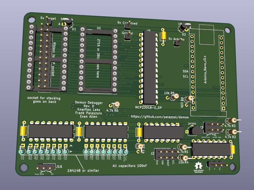
Debugger/Monitor for small "computers"
Chip select multiplexer is an open-source printed circuit board by palazzol, from the palazzol/demon repository on GitHub. It is a 2-layer board of 34.8 × 38.4 mm with 14 parts on 16 nets, routed with 37 tracks and 0 vias.
Its parts include 6 connectors, 1 capacitor and 1 IC. It belongs with the interfaces and adapters boards of this library.
Debugger/Monitor for small "computers"
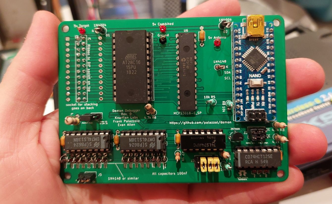
We would like to port this to more systems, and/or help others fix their old things. Please let us know if you need any help getting this system going, should you choose to give it a try!
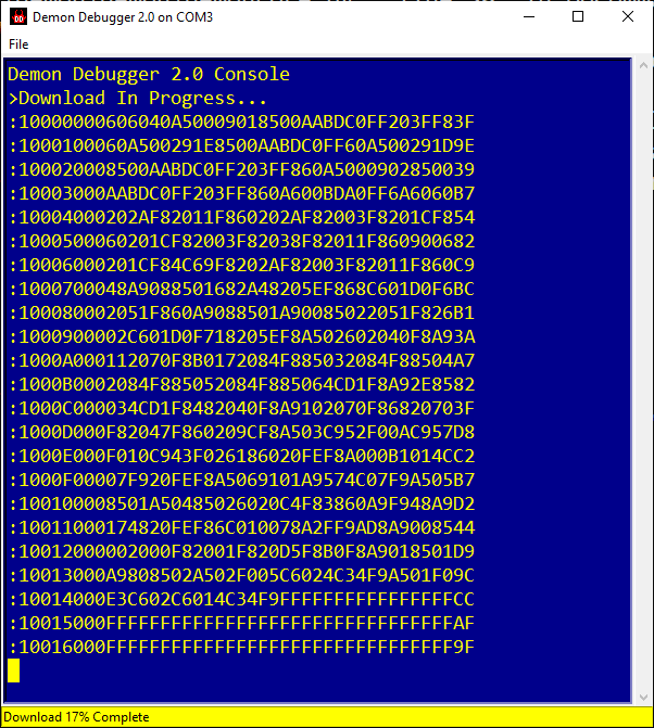
Demon Debugger is a tool that can be used to repair and reverse-engineer devices with 8 and 16 bit CPUs, such as arcade machines, console games, embedded computers, single board computers, etc. It provides a debugging console, and so is especially useful for systems that lack a working one.
It has been ported to Z80-based, 6502-based, 6800-based, 6809-based, and CP1610-based systems. There are ports underway to other CPU architectures.
Unfortunately, Demon Debugger can't be used on a totally broken system. The target system must have a working CPU, and at least a small amount of ROM and RAM. However, we have found that for most hardware, it's really not too hard to get a system to this point.
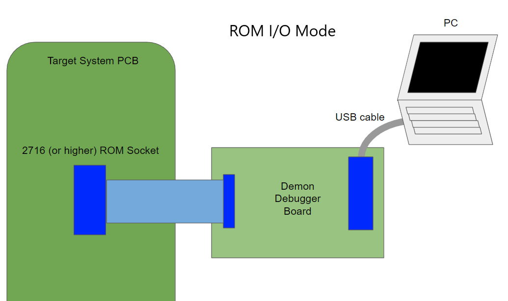
In ROM I/O mode, The Demon Debugger board cable plugs into a socket on the target system, in place of a standard JEDEC ROM/EPROM chip. Then, your PC can communicate with the target over serial, using a standard USB connection.
If your target system is already supported, there will be a target image already built, which you can upload onto your target.
To support a totally new target system, a small amount of tweaking may need to be done to the assembly code for your target. Generally, if you know the memory map for your system, this is really easy to do.
The Demon Debugger system has evolved over time. If you have a Demon Debugger board, you can use ROM I/O mode with prebuilt target code, and get started right away, without any other tools. If you need to support a new target, you can still use ROM I/O mode, once you build a new target code.
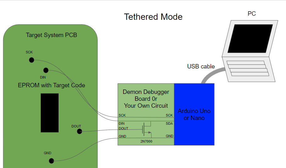
If you don't have a Demon Debugger board, you can still use the Demon Debugger system in Tethered mode, provided you have a few other capabilities. It requires only an Arduino Nano/Uno, a single transistor, and the ability to program an EPROM chip. You need to identify points on your target which can be used (2 outputs, 1 input, and a ground), wire up your modified Arduino accordingly, and modify the communication routines in the target to use those points. There are a few examples in the repo of doing this.
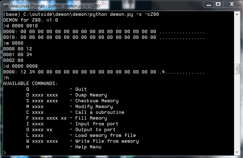
For now, please see the file demonapi.py
Tethered Mode - Sega Sound Board test Quality is not very good, but the Arduino module is next to the laptop
Intellivision Demo Better quality, no Arduino needed using native serialport on the LTO Flash cart.
| Qty | Value | Footprint | References |
|---|---|---|---|
| 1 | 0.1uF | Capacitor_THT:C_Axial_L3.8mm_D2.6mm_P7.50mm_Horizontal | C1 |
| 1 | 5v bus 1 | Connector_PinHeader_2.54mm:PinHeader_1x03_P2.54mm_Vertical | J2 |
| 1 | 5v bus 2 | Connector_PinHeader_2.54mm:PinHeader_1x01_P2.54mm_Vertical | J3 |
| 1 | 74LS138 | Package_DIP:DIP-16_W7.62mm | U1 |
| 1 | LOGO | Evan's misc parts:Evan Logo | G*** |
| 1 | LOGO | Evan's misc parts:OSHW gear | G*** |
| 1 | gnd bus | Connector_PinHeader_2.54mm:PinHeader_1x05_P2.54mm_Vertical | J1 |
| 1 | inputs | Connector_PinHeader_2.54mm:PinHeader_1x06_P2.54mm_Vertical | J4 |
| 1 | outputs | Connector_PinHeader_2.54mm:PinHeader_1x08_P2.54mm_Vertical | J5 |
| 1 | power in | Connector_PinHeader_2.54mm:PinHeader_1x02_P2.54mm_Vertical | J6 |
The 10 most common of 14 parts.
It measures 34.8 × 38.4 mm and has 2 copper layers, 1.6 mm thick.
14 parts. The full list of its parts is on this page, with links to each part's symbol and footprint where PCBKit's library has them.
From the palazzol/demon repository on GitHub, at the commit this page was made from: the board is hardware/chip select multiplexer/chip select multiplexer.kicad_pcb and its schematic hardware/DIP28 to TC53257F/DIP28 to TC53257F.kicad_sch. PCBKit opens the board in the browser, with nothing to install.
Its repository states no licence, so its author keeps all rights: ask palazzol before reusing the design.


google/mozc-devices
Circuit diagrams and firmware source code for Gboard DIY keyboards


hackclub/OnBoard
💡 Join 1,000 teenagers and make your first PCB with a $100 grant!


Twotoz/C5VRX
Ultra-minimal, zero-CPU 5.8 GHz analog FPV video receiver using ESP32-C5 Wi-Fi 6 PHY MODEM_DIAG, BitScrambler WBFM demodulation & resistor DAC CVBS

