2 layers143.5 × 70 mm
 pacmancoder/easy-pdk-mini21
Padauk MCU programmer variant for hand soldering.
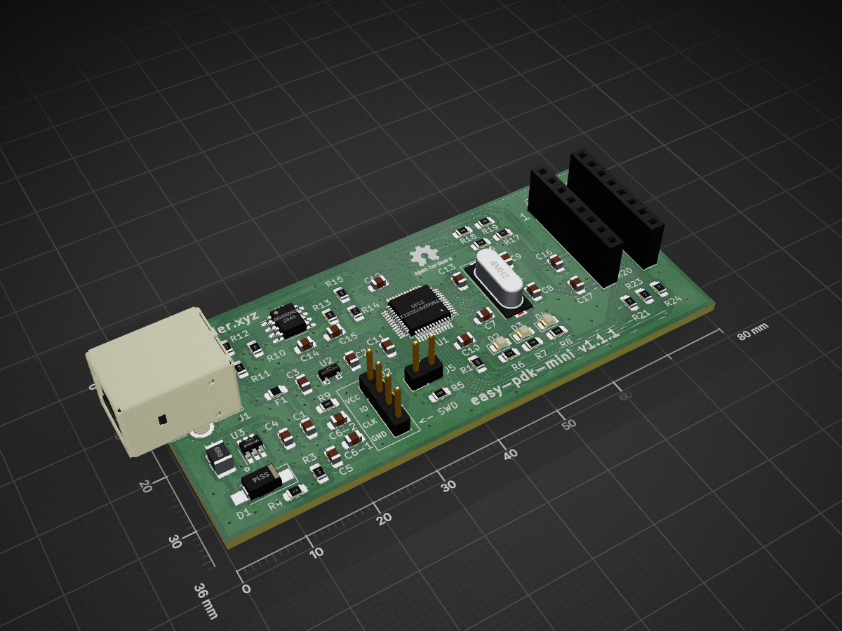
Freepdk is an open-source printed circuit board by pacmancoder, from the pacmancoder/easy-pdk-mini repository on GitHub, published under the CC-BY-SA-4.0 licence. It is a 2-layer board of 80 × 36 mm with 60 parts on 68 nets, routed with 538 tracks and 146 vias.
It is built around the LM358DR2GH, MT3608 and XC6206P332MR, with the SS14 among its other parts. Its parts include 23 resistors, 18 capacitors, 5 connectors, 4 ICs and 4 diodes. It belongs with the interfaces and adapters boards and the STM32 boards of this library.


Easy PDK mini is the programmer hardware variant originated from easy-pdk-programmer-hardware project.
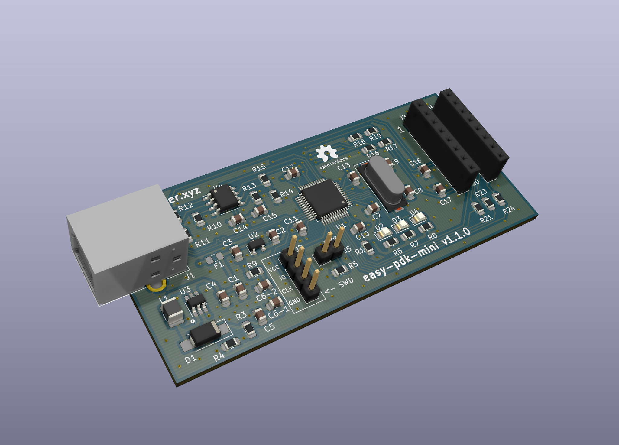
Schematics was simplified and the "lite" version of the programmer by tim_ was used as a base for this project, so in difference with the original hardware, this version works without MOSFET boost converter enable switch and negative voltage charge pump for the opamp.
Interactive BOM: link
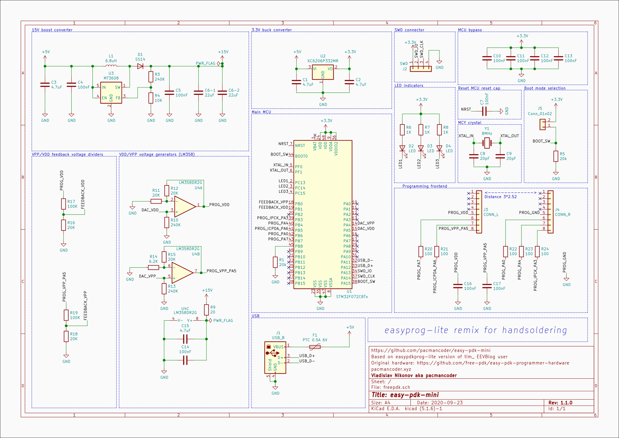
All passives have at least 0805 size, and the USB-B port was used instead of micro-USB, so it should be easy to solder this programmer by the hand. The only quirky parts which may be hard to solder is STM32 MCU and MT3608 boost converter.
Although existing "lite" version of easy-pdk-programmer (which was used as a reference for this project) is relatively simple by itself, some additional simplifications was made:
| Qty | Value | Footprint | References |
|---|---|---|---|
| 10 | 100nF | Capacitor_SMD:C_0805_2012Metric_Pad1.15x1.40mm_HandSolder | C4, C5, C7, C10, C11, C12, C13, C14, C16, C17 |
| 5 | 100 | Resistor_SMD:R_0805_2012Metric_Pad1.15x1.40mm_HandSolder | R20, R21, R22, R23, R24 |
| 5 | 20K | Resistor_SMD:R_0805_2012Metric_Pad1.15x1.40mm_HandSolder | R11, R12, R15, R16, R18 |
| 4 | 4.7uF | Capacitor_SMD:C_0805_2012Metric_Pad1.15x1.40mm_HandSolder | C1, C2, C3, C15 |
| 3 | 1K | Resistor_SMD:R_0805_2012Metric_Pad1.15x1.40mm_HandSolder | R6, R7, R8 |
| 3 | 240K | Resistor_SMD:R_0805_2012Metric_Pad1.15x1.40mm_HandSolder | R3, R10, R13 |
| 3 | LED | LED_SMD:LED_0805_2012Metric_Pad1.15x1.40mm_HandSolder | D2, D3, D4 |
| 2 | 100K | Resistor_SMD:R_0805_2012Metric_Pad1.15x1.40mm_HandSolder | R17, R19 |
| 2 | 20k | Resistor_SMD:R_0805_2012Metric_Pad1.15x1.40mm_HandSolder | R1, R5 |
| 2 | 20pF | Capacitor_SMD:C_0805_2012Metric_Pad1.15x1.40mm_HandSolder | C8, C9 |
| 2 | 22uF | Capacitor_SMD:C_0805_2012Metric_Pad1.15x1.40mm_HandSolder | C6-1, C6-2 |
| 1 | Symbol:OSHW-Logo2_7.3x6mm_SilkScreen | ||
| 1 | Symbol:KiCad-Logo2_5mm_SilkScreen | ||
| 1 | 10K | Resistor_SMD:R_0805_2012Metric_Pad1.15x1.40mm_HandSolder | R4 |
| 1 | 20 | Resistor_SMD:R_0805_2012Metric_Pad1.15x1.40mm_HandSolder | R9 |
| 1 | 6.2K | Resistor_SMD:R_0805_2012Metric_Pad1.15x1.40mm_HandSolder | R14 |
| 1 | 6.8uH | Inductor_SMD:L_1210_3225Metric_Pad1.42x2.65mm_HandSolder | L1 |
| 1 | 8MHz | Crystal:Crystal_SMD_HC49-SD | Y1 |
| 1 | CONN_L | Connector_PinSocket_2.54mm:PinSocket_1x08_P2.54mm_Vertical | J3 |
| 1 | CONN_R | Connector_PinSocket_2.54mm:PinSocket_1x08_P2.54mm_Vertical | J4 |
| 1 | Conn_01x02 | Connector_PinHeader_2.54mm:PinHeader_1x02_P2.54mm_Vertical | J5 |
| 1 | LM358DR2G | Package_SO:SOIC-8_3.9x4.9mm_P1.27mm | U4 |
| 1 | LOGO | QR:free-pdk-qr | G*** |
| 1 | MT3608 | Package_TO_SOT_SMD:SOT-23-6_Handsoldering | U3 |
| 1 | PTC 0.5A 6V | Fuse:Fuse_0805_2012Metric_Pad1.15x1.40mm_HandSolder | F1 |
| 1 | SS14 | Diode_SMD:D_SMA_Handsoldering | D1 |
| 1 | STM32F072C8Tx | Package_QFP:LQFP-48_7x7mm_P0.5mm | U1 |
| 1 | SWD | Connector_PinHeader_2.54mm:PinHeader_1x04_P2.54mm_Vertical | J2 |
| 1 | USB_B | Connector_USB:USB_B_OST_USB-B1HSxx_Horizontal | J1 |
| 1 | XC6206P332MR | Package_TO_SOT_SMD:SOT-23 | U2 |
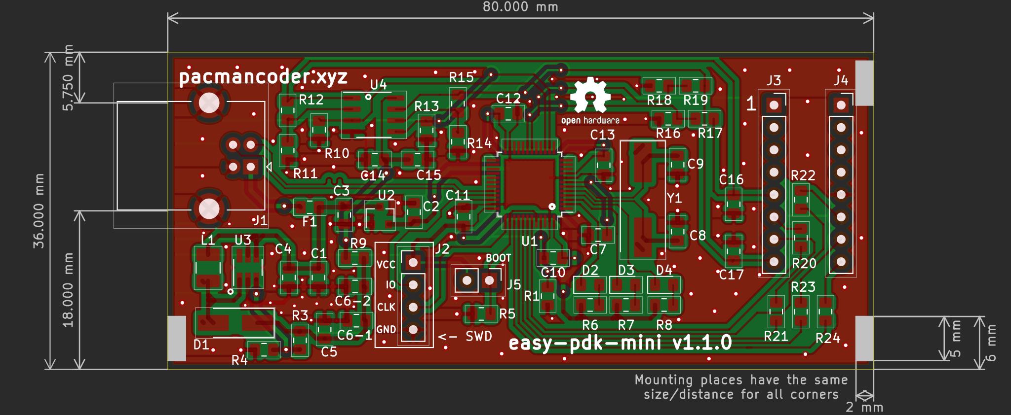
It measures 80 × 36 mm and has 2 copper layers, 1.6 mm thick.
60 parts, built around the LM358DR2GH, MT3608, XC6206P332MR and SS14. The full list of its parts is on this page, with links to each part's symbol and footprint where PCBKit's library has them.
From the pacmancoder/easy-pdk-mini repository on GitHub, at the commit this page was made from: the board is kicad/freepdk.kicad_pcb. PCBKit opens the board in the browser, with nothing to install.
Its repository publishes it under the CC-BY-SA-4.0 licence: you may reuse it on that licence's terms (keep the author's notice, and for a copyleft licence share your changes alike).

openUC2/TechnicalDocs-openUC2-HoloBox
This is the holographic box for openUC2


ajvizganapathy-pixel/XL4015-BuckConverter-5A-PCB
XL4015 5A step-down buck converter — KiCad PCB, gerbers, datasheets

akladnig/CamperVan
- CamperVan Design and Arduino Circuit Design - Campervan Design Overview - Dashboard App - Electrical System - Sensors - Circuit Design - Battery and voltage monitoring - Voltage Divider Design - Low Pass Filter - TODO

Many3Stars/Another-IoT-network-for-monitoring-forests
Author: Manuel Álvarez Herrera Supervisor: José Antonio García Souto Year: 2024

