2 layers55 × 106 mm

 Ozonised/SDC
ATmega 8 based self driving car.
SDC Schematic is an open-source printed circuit board by Ozonised, from the Ozonised/SDC repository on GitHub. It is a 2-layer board of 103 × 61 mm with 32 parts on 36 nets, routed with 177 tracks and 113 vias.
It is built around the ATMEGA8A-PU and L293D. Its parts include 9 connectors, 7 capacitors, 6 resistors, 3 ICs and 1 switch. It belongs with the AVR (ATmega, ATtiny) boards of this library.


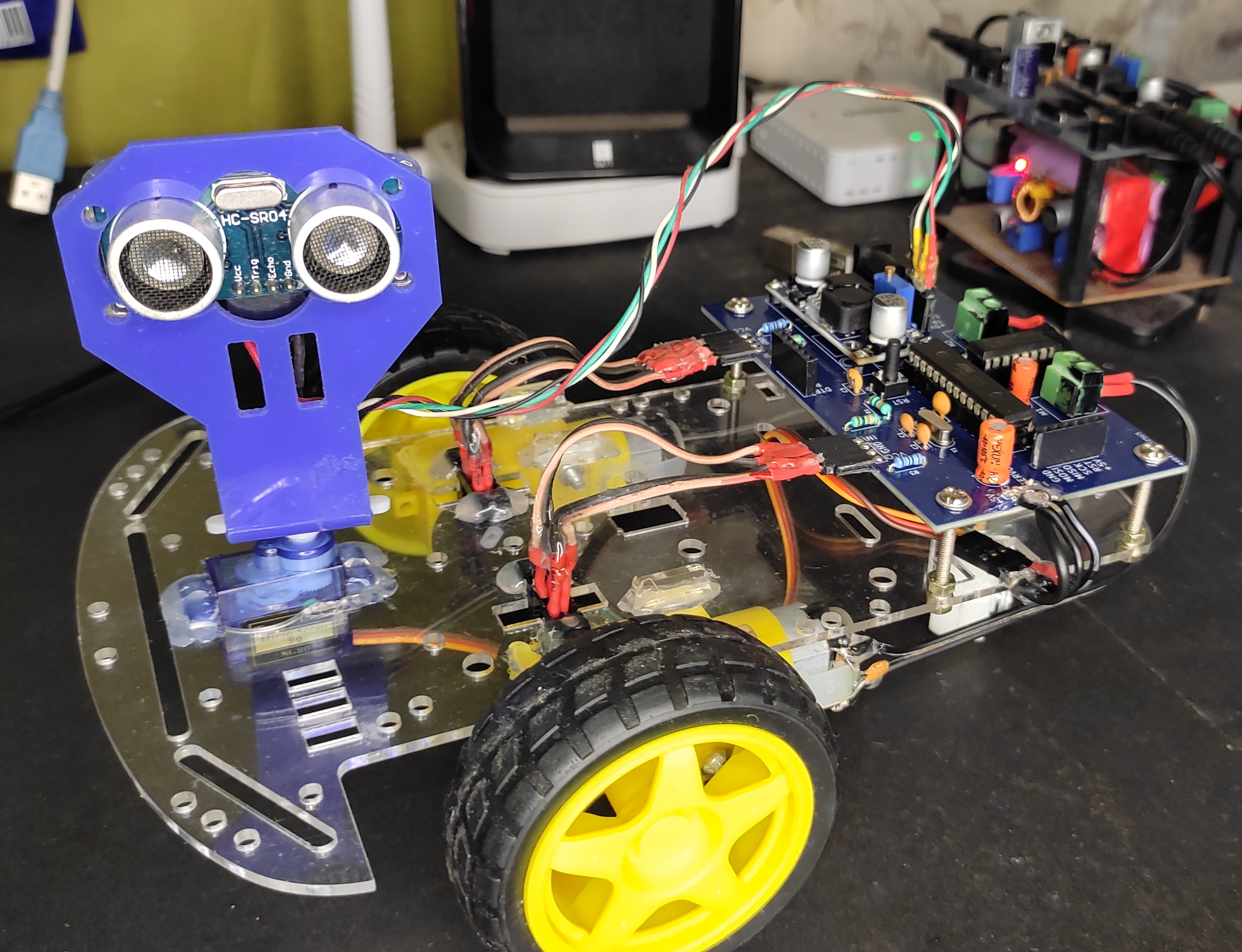 ATmega 8 based self driving car.
Watch the YouTube video to develop some comprehension.
The ATmega 8 is programmed using an ICSP programmer. In my case, I used an Arduino UNO as an ICSP programmer. By default, the microcontroller uses the internal 8MHz internal PC oscillator, but we want to use an external 16 MHz oscillator. So we need to make certain changes to the fuse bits of the ATmega 8. Below are the steps to do so:
ArduinoISP under File/Examples/ and hit upload.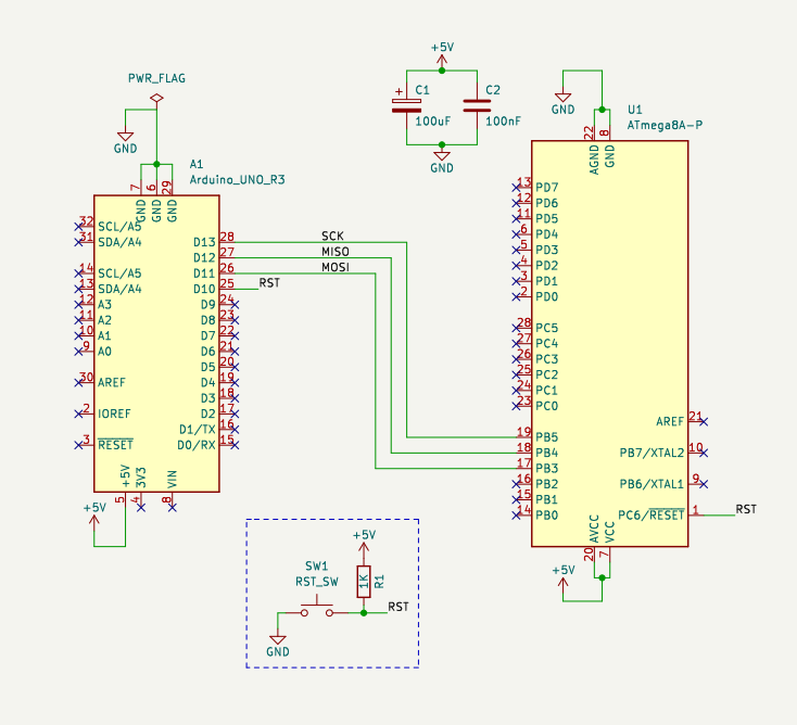
avrdude -c stk500v1 -P COM5 -p atmega8 -b 19200 -U lfuse:w:0xe4:m -U hfuse:w:0xd9:m. Alternatively, you can use an online AVR fuse bit calculator for your selected microcontroller. 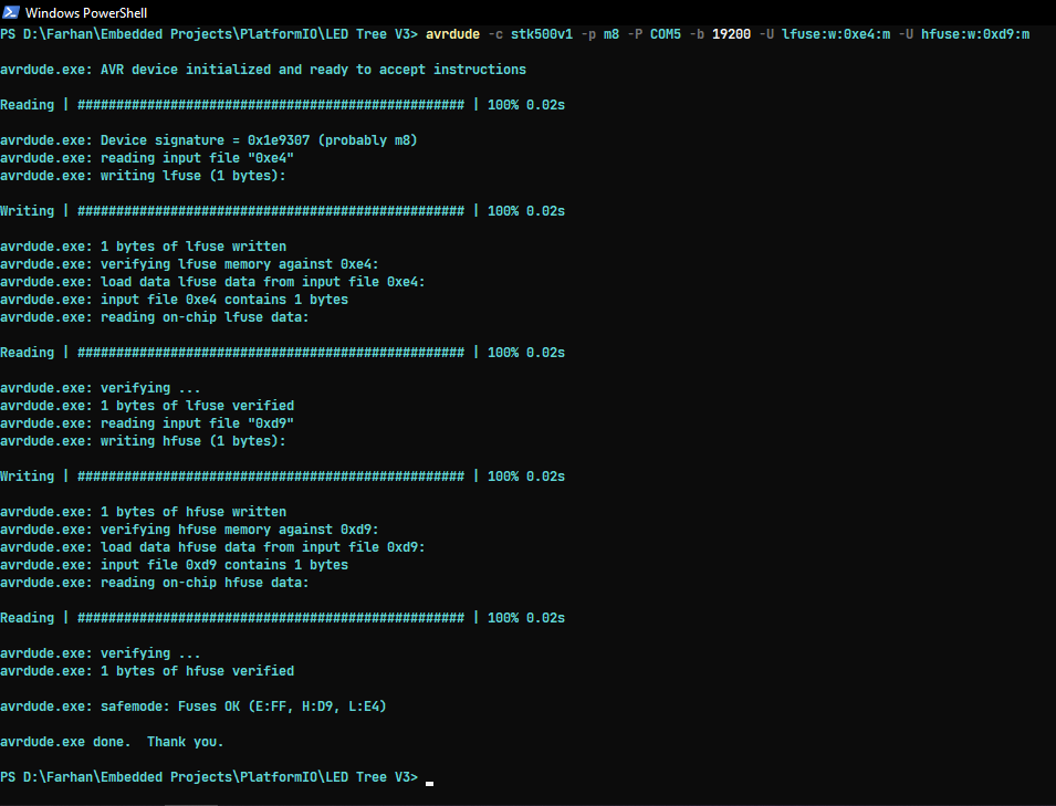
The -P <port>argument specifies the connection port. In my case, the arduino is connected to COM5 and hence the argument -P COM5. For -p <partno> either -p m8 or -p atmega8 can be used. Refer this guide for more information.
You can find the component list here.
The case along with the motor is available here: https://quartzcomponents.com/products/2wd-smart-robot-car-chassis-kit
MOC7811 optical encoders: https://quartzcomponents.com/products/moc-7811-encoder-sensor
HCSR04(Ultrasonic sensor): https://quartzcomponents.com/products/hc-sr04-ultrasonic-sensor-module?_pos=1&_sid=1f37cc7e0&_ss=r
Ultrasonic sensor mount: https://quartzcomponents.com/products/ultrasonic-sensor-mounting-bracket-for-hc-sr04?_pos=3&_sid=1f37cc7e0&_ss=r
| Qty | Value | Footprint | References |
|---|---|---|---|
| 4 | MountingHole | MountingHole:MountingHole_3.5mm | H1, H2, H3, H4 |
| 3 | 100nF | Capacitor_THT:C_Disc_D5.0mm_W2.5mm_P2.50mm | C3, C4, C5 |
| 3 | 10K | Resistor_THT:R_Axial_DIN0207_L6.3mm_D2.5mm_P7.62mm_Horizontal | R1, R4, R5 |
| 3 | 680 | Resistor_THT:R_Axial_DIN0207_L6.3mm_D2.5mm_P7.62mm_Horizontal | R2, R3, R6 |
| 3 | Conn_01x04 | Connector_PinSocket_2.54mm:PinSocket_1x04_P2.54mm_Vertical | J4, J5, J8 |
| 2 | 22pF | Capacitor_THT:C_Disc_D3.0mm_W2.0mm_P2.50mm | C1, C2 |
| 2 | Conn_01x06_Socket | Connector_PinSocket_2.54mm:PinSocket_1x06_P2.54mm_Vertical | J6, J9 |
| 2 | Screw_Terminal_01x02 | TerminalBlock:TerminalBlock_Altech_AK300-2_P5.00mm | J1, J2 |
| 1 | 100uF | Capacitor_THT:CP_Radial_D6.3mm_P2.50mm | C6 |
| 1 | 16MHz | Crystal:Crystal_HC49-4H_Vertical | Y1 |
| 1 | 220uF | Capacitor_THT:CP_Radial_D6.3mm_P2.50mm | C7 |
| 1 | ATmega8A-P | Package_DIP:DIP-28_W7.62mm | U1 |
| 1 | Conn_01x03_Pin | Connector_PinHeader_2.54mm:PinHeader_1x03_P2.54mm_Vertical | J7 |
| 1 | Jack-DC | Connector_BarrelJack:BarrelJack_Horizontal | J10 |
| 1 | L293D | Package_DIP:DIP-16_W7.62mm | U2 |
| 1 | LM2596_module | lm2596_module:LM2596_module | U4 |
| 1 | SW_SPST | Button_Switch_THT:SW_PUSH_6mm_H4.3mm | SW1 |
The 31 most common of 32 parts.
It measures 103 × 61 mm and has 2 copper layers, 1.6 mm thick.
32 parts, built around the ATMEGA8A-PU and L293D. The full list of its parts is on this page, with links to each part's symbol and footprint where PCBKit's library has them.
From the Ozonised/SDC repository on GitHub, at the commit this page was made from: the board is SDC_Schematic/SDC_Schematic.kicad_pcb and its schematic SDC_Schematic/SDC_Schematic.kicad_sch. PCBKit opens the board in the browser, with nothing to install.
Its repository states no licence, so its author keeps all rights: ask Ozonised before reusing the design.


uHappyLogic/lineFollower
2015 LinerFollowers competion hosted by Posen University of Technology winner https://www.youtube.com/watch?v=CigrI7Yh1Fk


str-dst/USBasp-MultiPad
This work is licensed under a [Creative Commons Attribution-ShareAlike 4.0 International License][cc-by-sa].

th-in-gs/SwitchDualShockAdapter
KiCad project, with schematic and PCB layout. The PCB should be run through the "Round Tracks" plugin before production.

2pkstartup/DymBOX
Regulátor teploty pro udírnu postavený na mikrokontroléru ATmega8.
