Higher lower is an open-source printed circuit board by oskitone, from the oskitone/higher_lower repository on GitHub, published under the CC-BY-SA-4.0 licence. It is a 2-layer board of 63.5 × 38.1 mm with 20 parts on 15 nets, routed with 65 tracks and 0 vias.
It is built around the ATTINY85V-10PU. Its parts include 3 switches, 2 capacitors, 2 resistors, 1 IC and 1 diode. It belongs with the AVR (ATmega, ATtiny) boards of this library.
Obviously, I'd prefer you buy the kit from me. But, if circumstances prohibit, I've uploaded the Higher Lower PCB to OSH Park; please buy it from them with my blessing.
How to play "Higher Lower"
Two different tones play. Is the second tone higher or lower than the first? The more guesses you get right, the harder it gets!
Four guesses per round, ten rounds per game. Any wrong guess and the game resets.
Your score is how many rounds have passed, and it's announced after each round as a series of happy trill noises.
For a multiplayer game, hand off to the next player after each round. The last player to successfully complete their round wins.
At the start of each new game, the "Higher Lower" theme song plays. It is a very good song.
Upon completing all ten rounds of guesses and winning the game, the theme plays again, faster and faster and faster until the machine finally resets into a new game at a harder difficulty setting.
Adjust volume and game difficulty by opening the enclosure and adjusting trim potentiometers on the PCB.
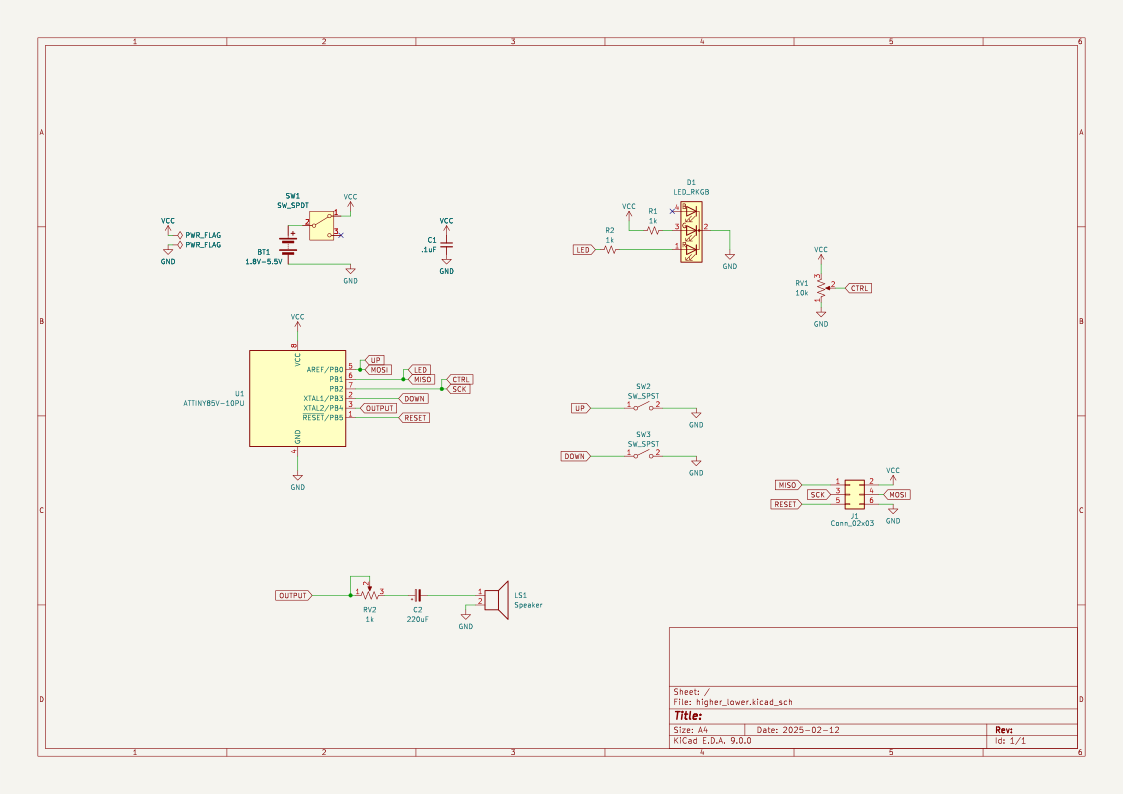
Schematic
In pursuit of a small BOM and quick assembly, there are a few concessions:
There's no amplifier, just the IC to volume pot to cap to speaker. In theory, the speaker can draw more current than the chip can supply, causing it to overheat. In practice, it hasn't been an issue.
There's a small .1uF bypass cap to smooth out power supply noise. Normally there's a big one too like the Scout's 220uF electrolytic cap. Again, in practice, its absence hasn't been an issue.
Running, deploying
text
./run.sh -h
Requires arduino-cli to compile, Ardens to emulate, then a Sparkfun programmer to upload. (Other programmers may work just as well, but I've only tested this one.)
Deployment troubleshooting
Could not find USBtiny device: Programmer not connected?
Programmer operation not supported: Make sure board is getting full power. Try setting "CTRL" pot to its middle value. (Some pins to programmer are shared with game inputs.)
Arduboy
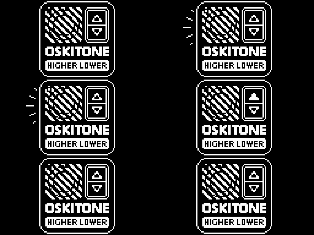
You can also deploy to an Arduboy using the Arduino IDE. Play using the device's Up/Down buttons.
(And you can play an online emulation of "Higher Lower" on the Arduboy here!)
3D Models
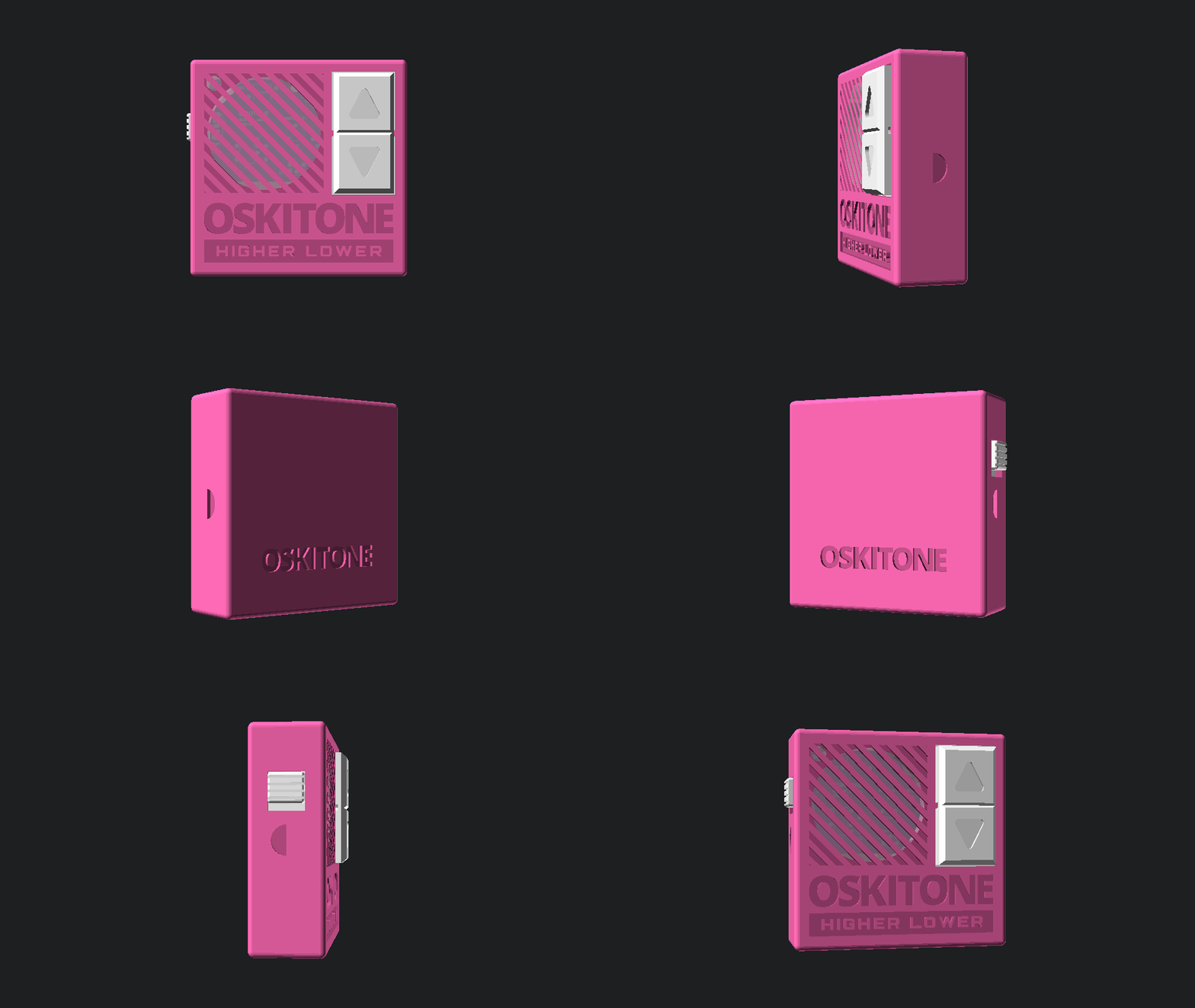
higher_lower's 3D-printed models are written in OpenSCAD.
Dependencies
Assumes parts_cafe and scout repos are in sibling directories and are both up to date on the main branch. Here's how I've got it:
It measures 63.5 × 38.1 mm and has 2 copper layers, 1.6 mm thick.
What parts does the Higher lower use?
20 parts, built around the ATTINY85V-10PU. The full list of its parts is on this page, with links to each part's symbol and footprint where PCBKit's library has them.
Where can I download the Higher lower KiCad files?
From the oskitone/higher_lower repository on GitHub, at the commit this page was made from: the board is kicad/higher_lower.kicad_pcb and its schematic kicad/higher_lower.kicad_sch. PCBKit opens the board in the browser, with nothing to install.
Can I use the Higher lower design in my own project?
Its repository publishes it under the CC-BY-SA-4.0 licence: you may reuse it on that licence's terms (keep the author's notice, and for a copyleft licence share your changes alike).
This Repo is a collection of project files to a series of KiCad 7 tutorial, Which will take you through the journey of learning KiCad from scratch to making your first Printed Circuit Board.