2 layers78 × 130 mm
Lofence
kiu/lofence
LoFence is a LoRaWAN capable IoT electric fence monitoring system running on the The Things Network.
65 parts142MIT

 oshwa/OHS2024Badge4
Hack your OHS 2024 Badge!
OHS2024 Badge Release is an open-source printed circuit board by oshwa, from the oshwa/OHS2024Badge repository on GitHub, published under the MIT licence. It is a 4-layer board of 93.8 × 126.9 mm with 43 parts on 49 nets, routed with 479 tracks and 70 vias.
It is built around the ATMEGA328PB-AU and CR203223F. Its parts include 13 resistors, 9 diodes, 3 connectors, 2 switches and 1 capacitor. It belongs with the lEDs and displays boards and the AVR (ATmega, ATtiny) boards of this library.


Hack your OHS 2024 Badge! There will be a hacking station during the summit to modify the badge code (we'll supply some programmers). If you want to add some of your own hardware to the badge, bring some tools and components to make your own SAO!
The front and back of the badge:
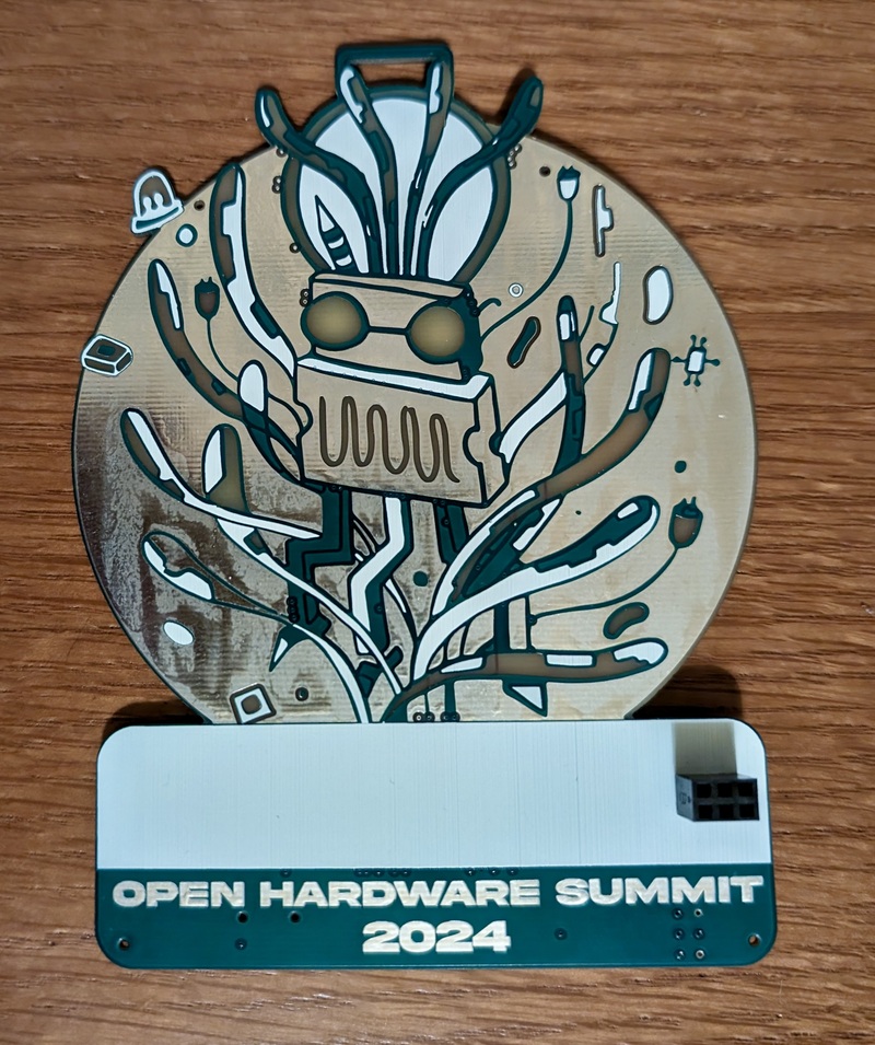
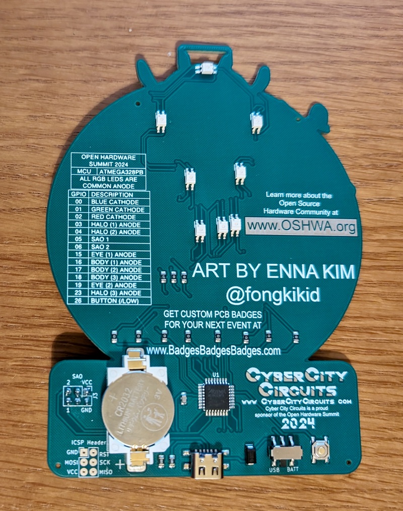
The badge features some amazing art by Enna Kim and was created by Cyber City Circuits.

The badge features:
The badge is compatible with Arduino IDE. However, there is no USB data connection so the badge has to have an external programmer to modify the code on the microcontroller. An easy programmer to use is the USBtinyISP which is affordable and open source. Here is a version of the board sold on Amazon:
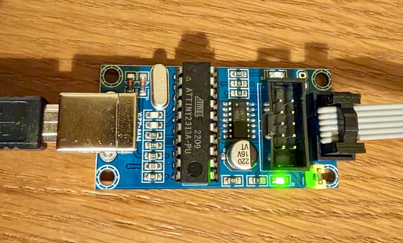
You may need to install drivers on Windows: https://learn.adafruit.com/usbtinyisp/download
The board uses MiniCore with the Arduino IDE. Follow these instructions to install MiniCore: https://github.com/MCUdude/MiniCore?tab=readme-ov-file#how-to-install
Clone this repository and open OHS2024Badge.ino in the Arduino IDE.
Connect the USBtinyISP programmer to your computer.
From the Tools menu select:
NOTE: You do not need to set the port, the programmer will be seen as a USB device by the operating system.
Build the code by selecting from the menu Sketch -> Verify/Compile. If all goes well, the code should compile without any errors.
Now for the tricky part: We have to hold the programmer spring-loaded (pogo) pins directly onto the exposed ICSP pads on the back of the Badge. Make sure the pins from the programmer line up with the pads on the badge. There are often labels written directly on the PCBs that tell you which pin is which. If the badge becomes powered by the programmer, you know the connection is being made properly. The following pictures show how the 2x3 pin header is arranged and how to hold spring-loaded pins directly onto the badge PCB:
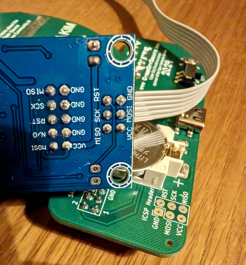
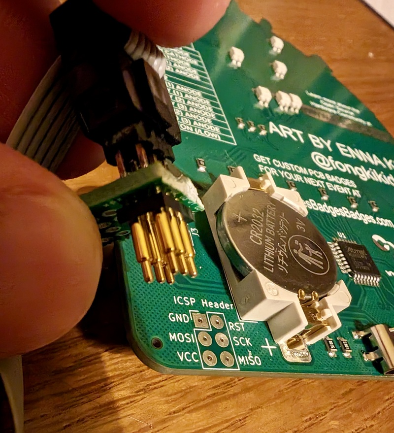
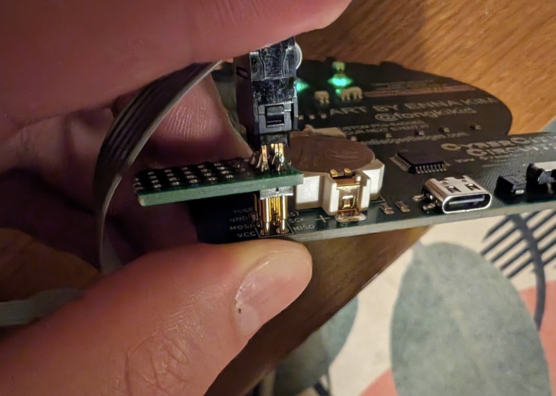
While holding the pins directly onto the badge, in the Arduino IDE click the menu item Sketch -> Upload Using Programmer and wait for the upload process to finish. The upload progress is shown in the IDE Output.
There are easier ways to hold the pins to the badge, such as a clip or a custom jig to clamp the pogo pins. Bring your own if you have one handy!
The default code already loaded on the badge is available in the example folder: examples/DefaultBadge/OHS2024BadgeDefault.ino
A simplified sample is provided in the main directory: OHS2024Badge.ino.
You can modify it to make your own custom animations!
The Simple Add-On (SAO) connector provides power and two GPIO pins for badge addons!
| Qty | Value | Footprint | References |
|---|---|---|---|
| 8 | 100Ω | CCC-Parts-Library:BADGE - R_0805 | R10, R11, R12, R13, R14, R15, R16, R17 |
| 8 | LED_RABG | CCC-Parts-Library:BADGE - LED RGB Reverse XZMDKCBDDG45S-9 | D1, D2, D3, D4, D5, D6, D7, D8 |
| 6 | Graphics | , , , , , | |
| 2 | , | ||
| 2 | 5.1kΩ | CCC-Parts-Library:BADGE - R_0805 | R2, R3 |
| 1 | clipboard:97555b4e-9b7d-406b-90f1-653a2ee528b9 | ||
| 1 | 0.1uF | CCC-Parts-Library:BADGE - C_0805 | C1 |
| 1 | ATmega328PB-A | Package_QFP:TQFP-32_7x7mm_P0.8mm | U1 |
| 1 | CR20322 | CCC-Parts-Library:BADGE - CR2032 HOLDER C964760 | BT1 |
| 1 | D | CCC-Parts-Library:BADGE - DO-214AC | D10 |
| 1 | ICSP Header | CCC-Parts-Library:Badge - ICSP Header (SMT) | J2 |
| 1 | LOGO | CCC_Drawings:Logo - Cyber City Circuits - Two Line 30mm (Shiny) | G*** |
| 1 | LOGO | LOGO | G*** |
| 1 | R_B | CCC-Parts-Library:BADGE - R_0805 | R4 |
| 1 | R_G | CCC-Parts-Library:BADGE - R_0805 | R5 |
| 1 | R_R | CCC-Parts-Library:BADGE - R_0805 | R6 |
| 1 | SAO Header | CCC-Parts-Library:Badge - SAO Header | J3 |
| 1 | SW_Push | CCC-Parts-Library:BADGE - BUTTON | SW2 |
| 1 | SW_SPDT | CCC-Parts-Library:BADGE - SWITCH C963207 | SW1 |
| 1 | USB_C_Power_Only_C2927027 | CCC-Parts-Library:BADGE - USB C Power Only C2927027 | J1 |
The 41 most common of 43 parts.
kiu/lofence
LoFence is a LoRaWAN capable IoT electric fence monitoring system running on the The Things Network.

silvervest/c64pico
This is a tiny emulated C64 running on a Raspberry Pi Pico! Full details of the build can be found at https://www.youtube.com/watch?v=hgLhGpbC6E4

c0pperdragon/SIO2SD
An Arduino-based floppy drive emulator for the atari 8 bit computers.

valerionew/very-good-uc-doggos
A special graduation present for a special friend. Six microcontrollers in one devboard

ageppert/Brushless-Motor-Biz-Card
A brushless motor and driver built in to a business card form-factor for learning and experimenting!

orangeglo/PS2PSP
Board to connect a PS2 controller to a PSP 2000 (PSP Consolizer)

latonita/jeep-canbus
Projects around CAN BUS in Chrysler Jeep - VES enabler, other small features

It measures 93.8 × 126.9 mm and has 4 copper layers, 1.6 mm thick.
43 parts, built around the ATMEGA328PB-AU and CR203223F. The full list of its parts is on this page, with links to each part's symbol and footprint where PCBKit's library has them.
From the oshwa/OHS2024Badge repository on GitHub, at the commit this page was made from: the board is hardware/OHS2024 Badge Release/OHS2024 Badge Release.kicad_pcb and its schematic hardware/OHS2024 Badge Release/OHS2024 Badge Release.kicad_sch. PCBKit opens the board in the browser, with nothing to install.
Its repository publishes it under the MIT licence: you may reuse it on that licence's terms (keep the author's notice, and for a copyleft licence share your changes alike).