2 layers169.9 × 153.5 mm

 orihikarna/Hermit9
An ergonomic keyboard project
Stm32tiny is an open-source printed circuit board by orihikarna, from the orihikarna/Hermit repository on GitHub, published under the CC0-1.0 licence. It is a 2-layer board of 24.8 × 17.8 mm with 30 parts on 41 nets, routed with 2,197 tracks and 18 vias.
Its parts include 9 capacitors, 9 resistors, 4 connectors, 3 diodes and 2 ICs. It belongs with the keyboards and input boards and the STM32 boards of this library.
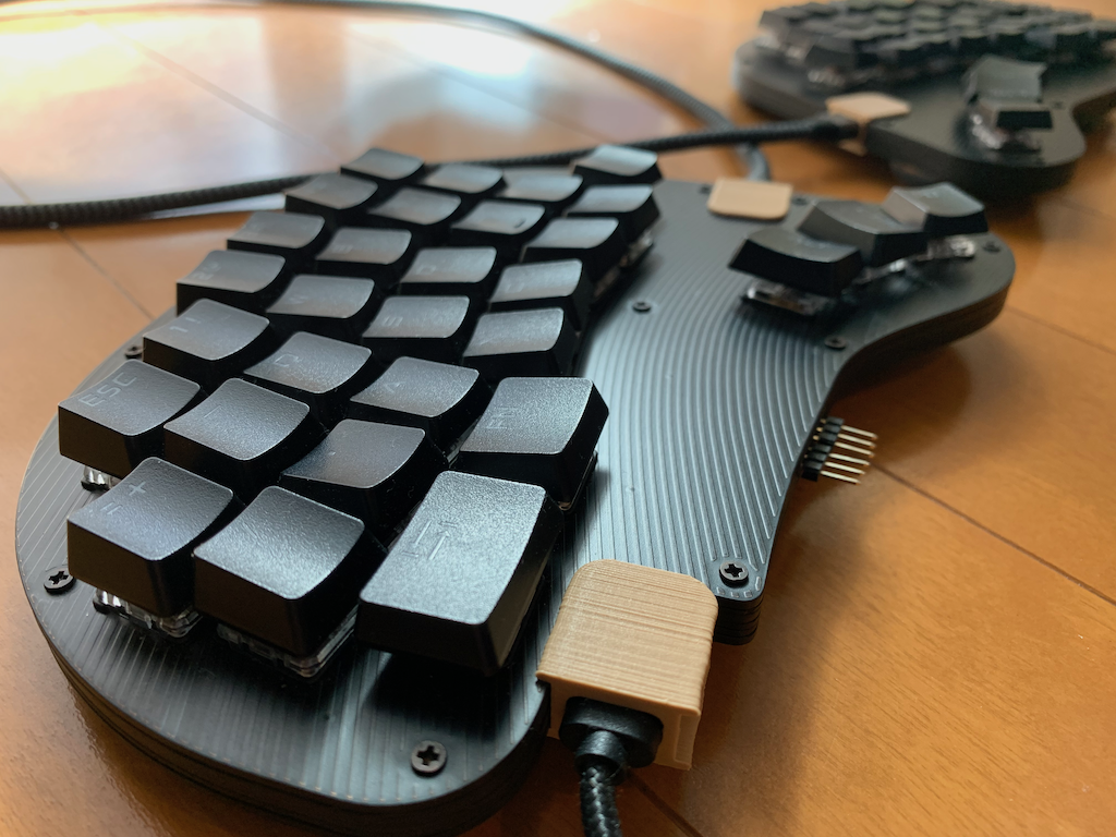
This is a personal hobby project on DIY keyboard. The name Hermit comes from its key switch layout: it looked like a hermit crab.
Before working on this "full" keyboard, I made a test split keypad with 10 keys as a proof of concept model, which was named Zoea.
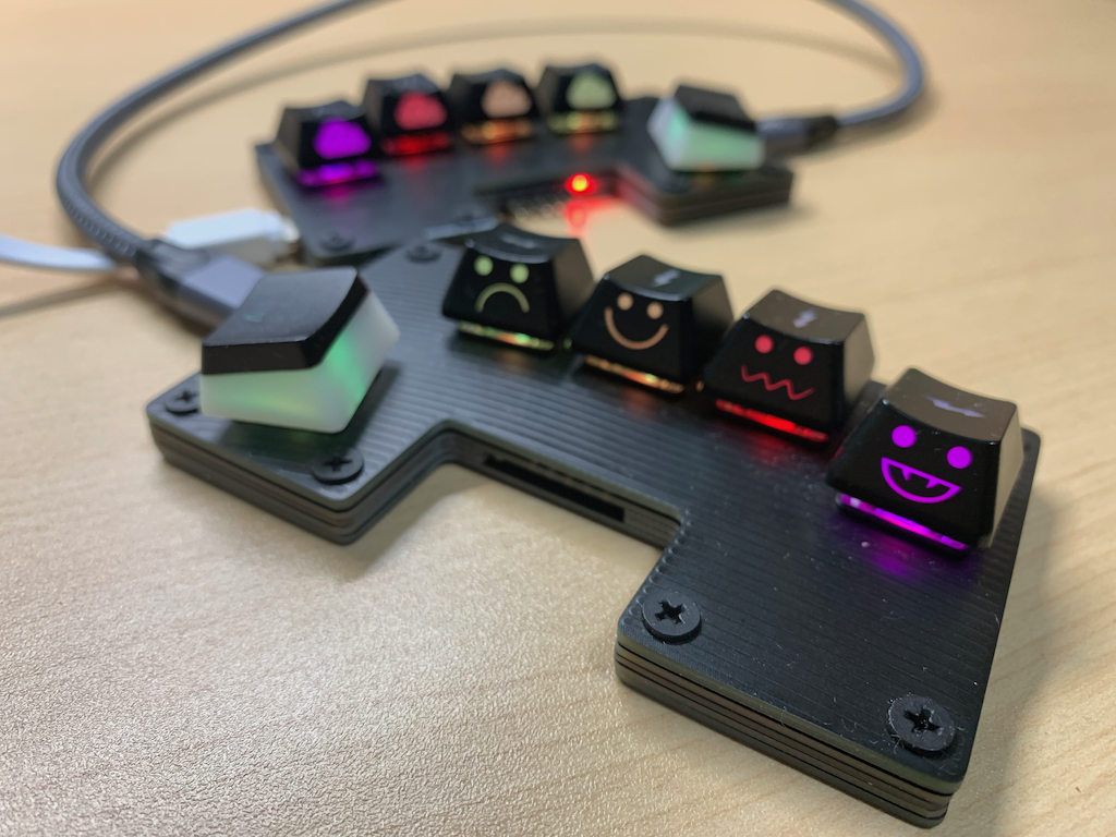
C-d -> Del)Before assembling ErgoDash, I really liked the key touch of Realforce and had used it for a decade.
However, once I got used to ErgoDash, I could not go back to Realforce anymore because B key was too far for my left index finger.
In fact, I started feeling pain in the index finger after typing on Realforce for a day.
One day, I came across Treadstone layout, where the B key, or the left half of the bottom row, is shifted to the left a bit.
I thought this is the answer for me and I should follow this design.
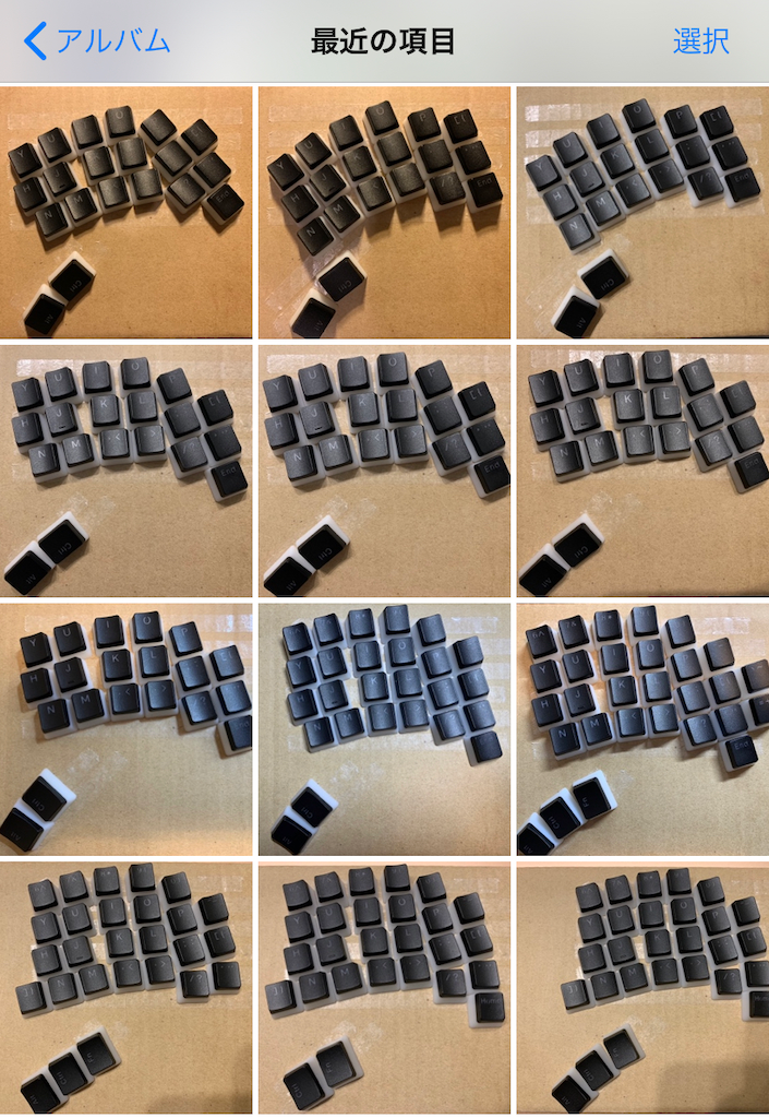
To begin with, I placed keycaps on a cardboard with lines of double sided tapes on it, and try tapping on it. Sometimes added more keys, and other times removed some of them to find one that suits my fingers.
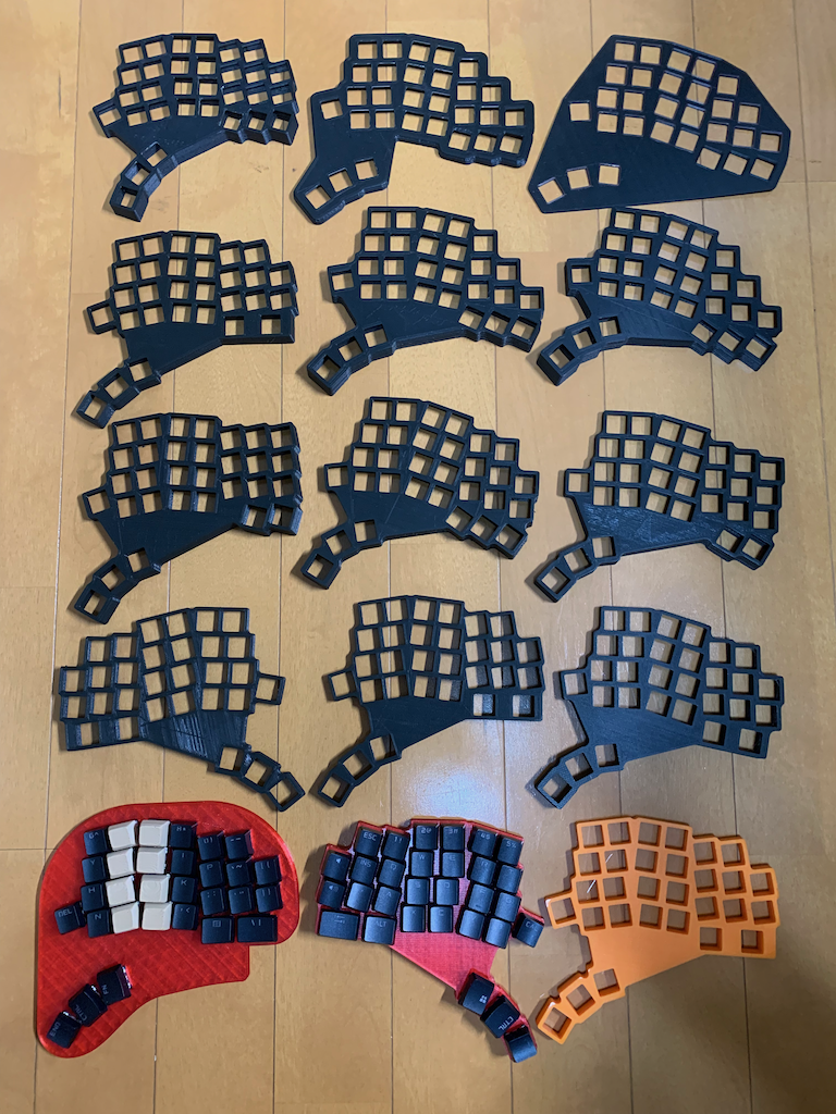
After I purchased a 3D printer, I continued the seek for the layout using the actual Choc V2 key switches on 3D printed frames. It enabled me to more finely adjust:
I usually use Japanese key layouts, and I found that 60 keys is the minimum that I can accept. I wanted to keep most of the symbol keys on the board (without layers).
When the layout was roughly determined, I tried to parametrize the layout to adjust the degree of ergonomic-ness. The strategies are:
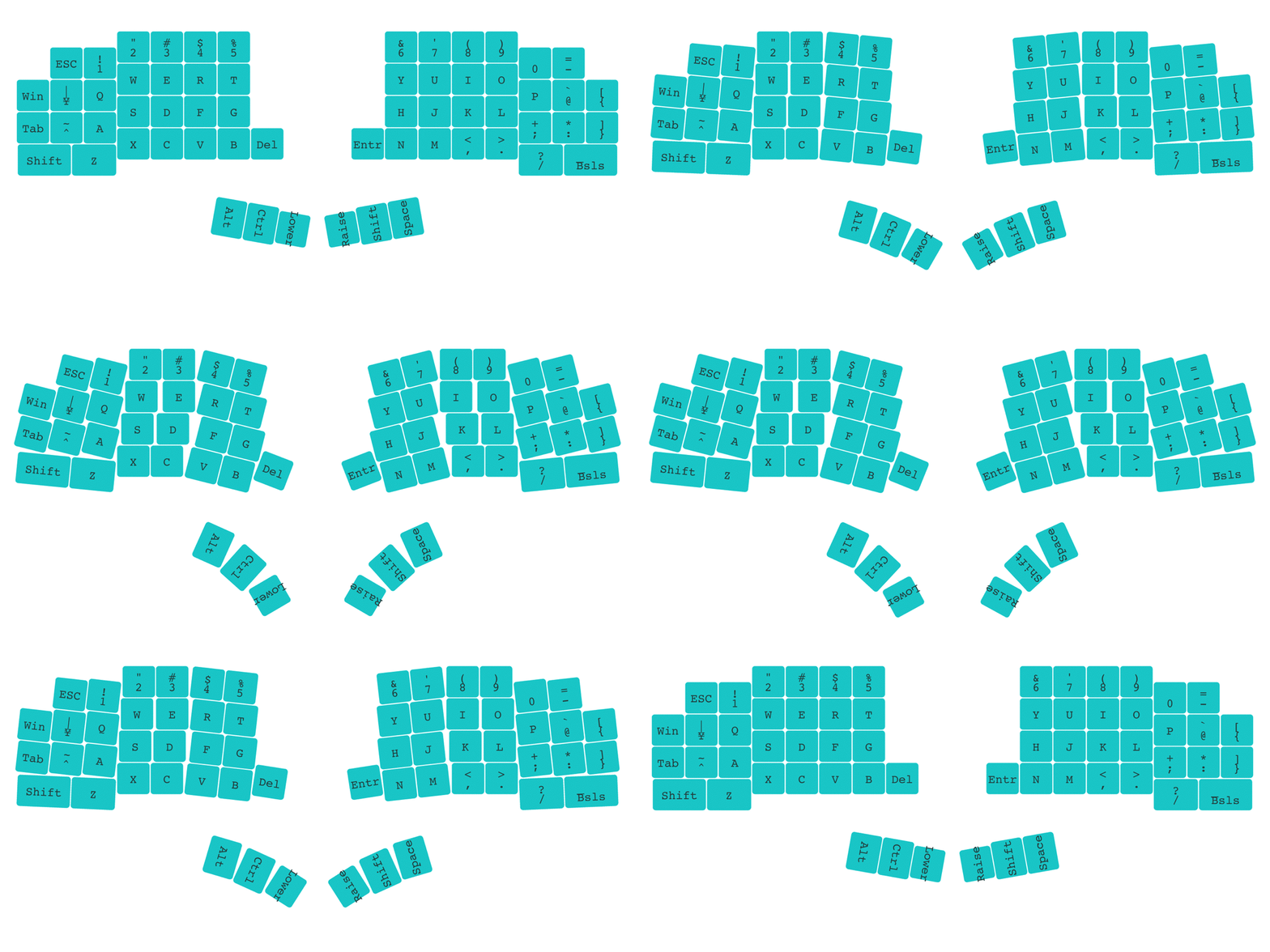
B is a bit on the left of GAnd finally settled down on the current layout.
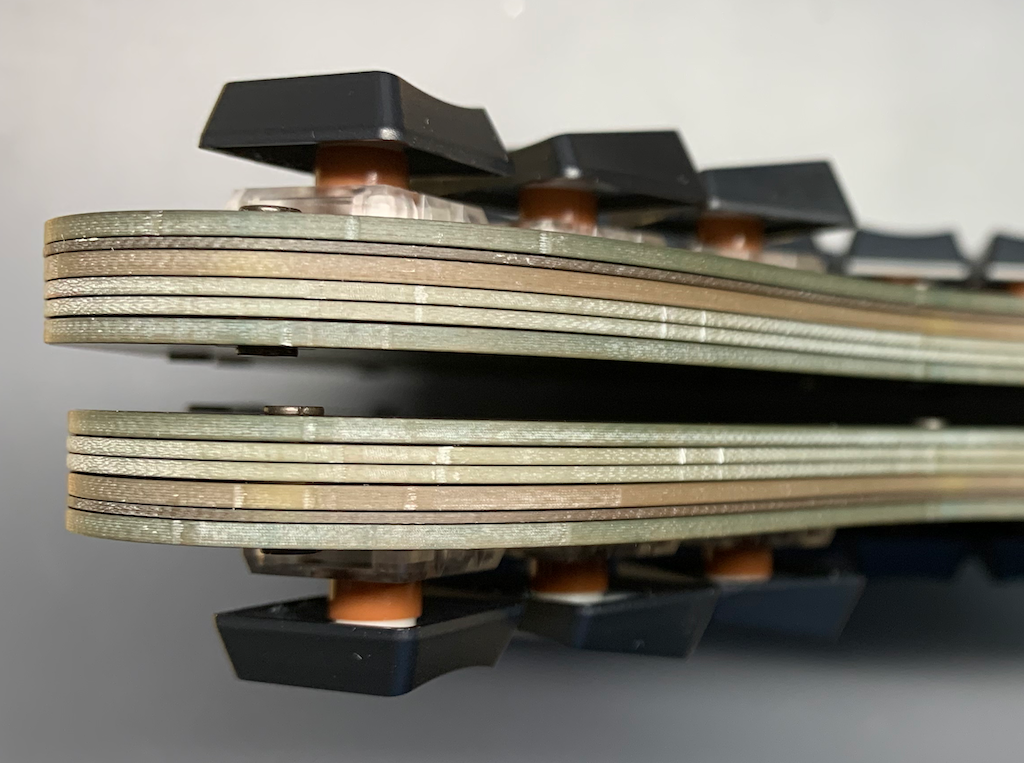
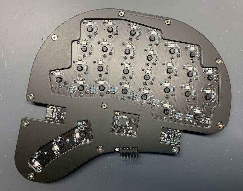
This keyboard is composed of 6 PCB layers and is 8mm thick in total.
I used KiCad v5.1.5 for the PCB design.
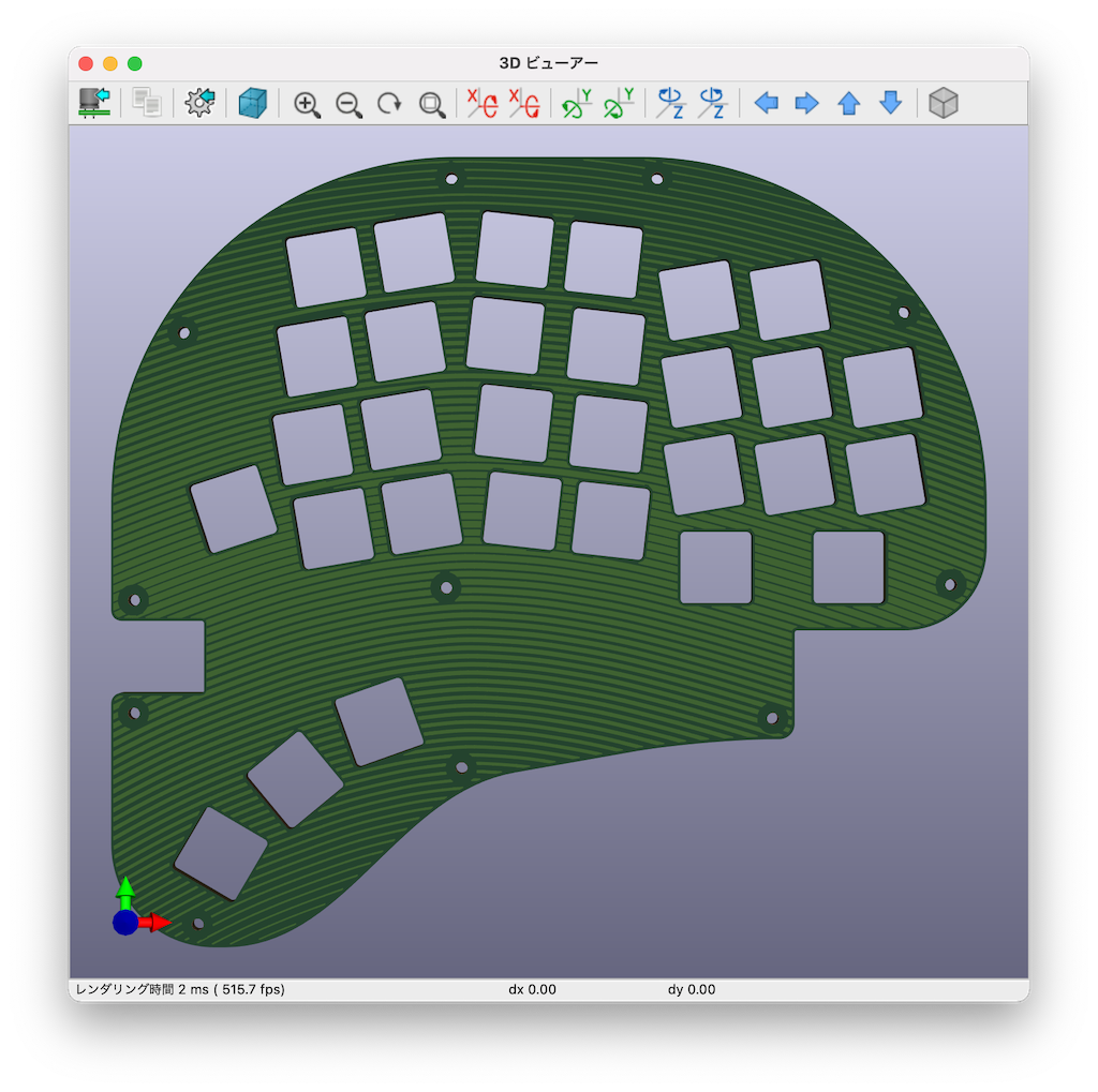
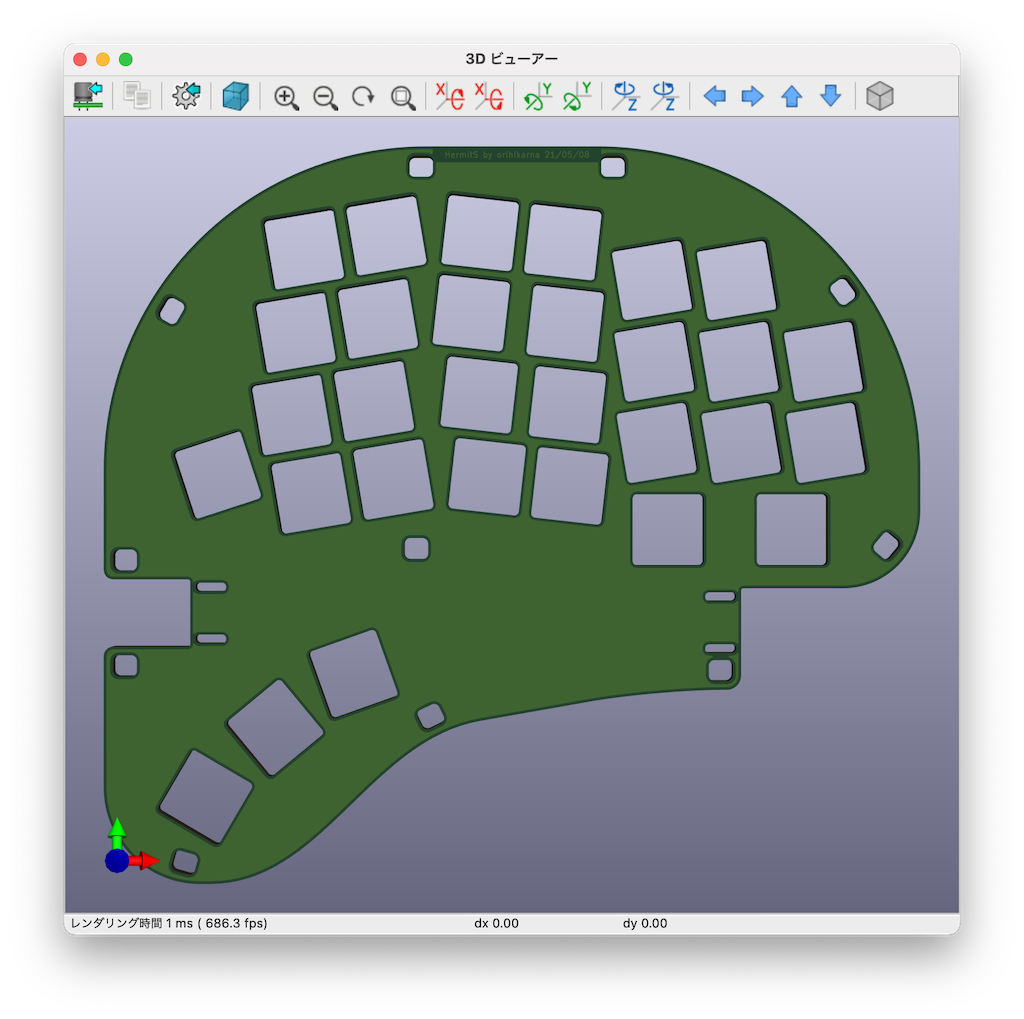
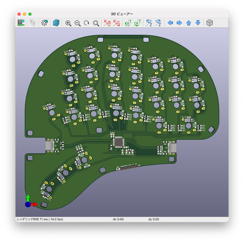
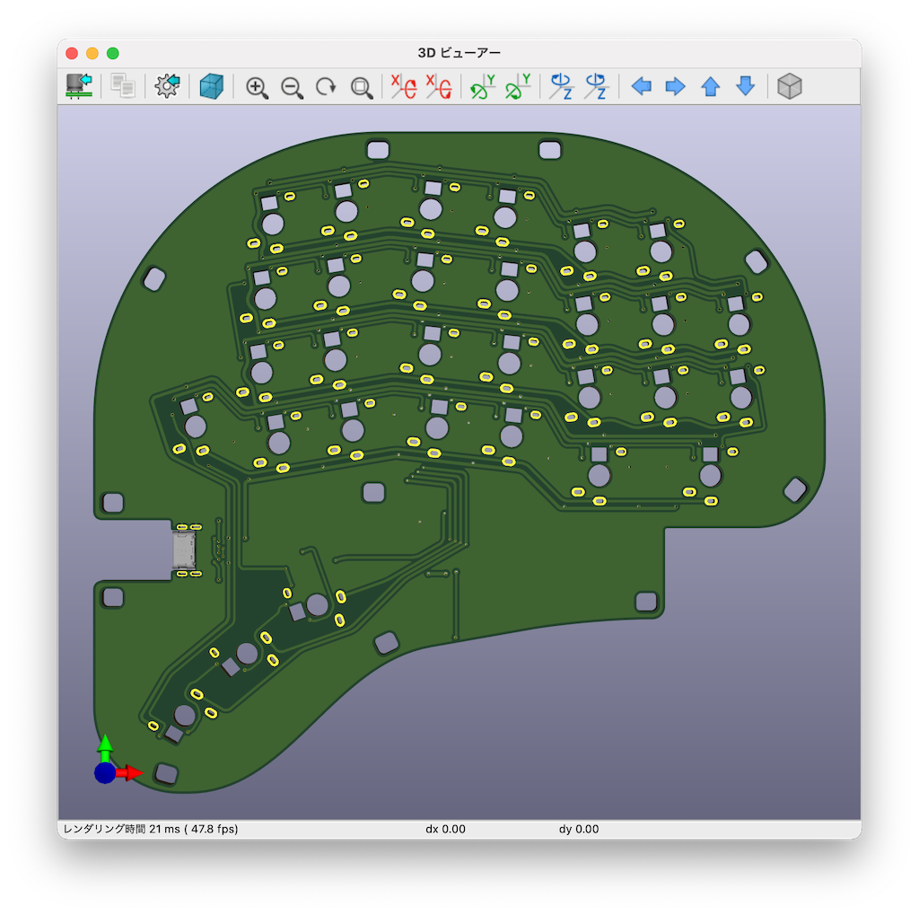
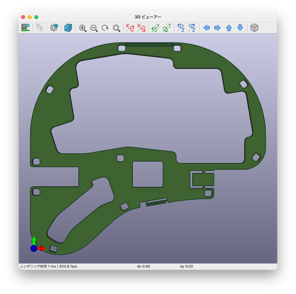
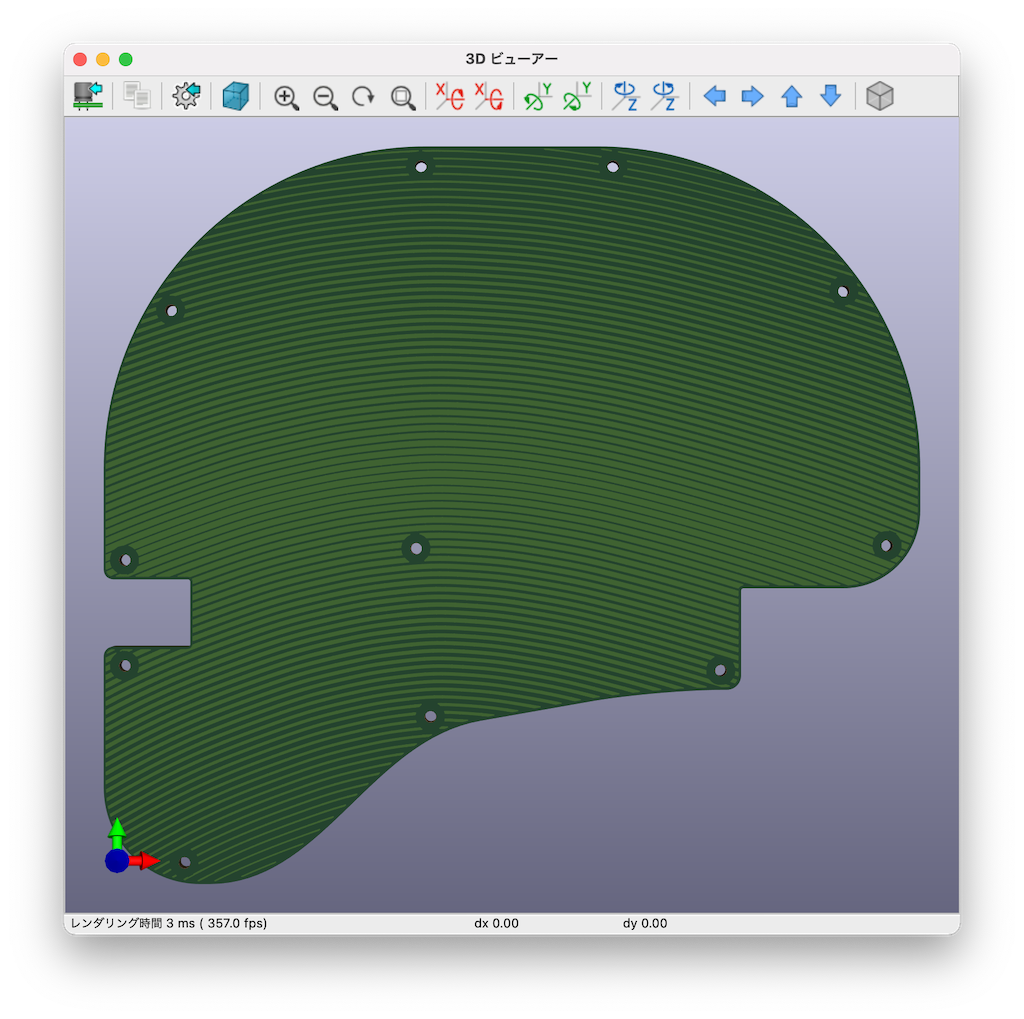
All the footprint placement, wire routing, vias, silkscreen labels, Edge.Cuts and GND zones are done by a Python script.
Currently, only the component side (Front or Back) needs to be set manually first.
Then, from Script Console of Pcbnew layout editor, run
exec(open('/(your path)/Hermit/python/place-route-Hermit.py').read())and everything will be done in seconds! (Although it took 2 month for me to write the script, of course!)
For example, in the script, the wire from C21 (debounce capacitor) pad 1 to U1 (main mcu) pad 29 is written as:
('C21', '1', 'U1', '29', w_mcu, (Dird, 90, ([(5.8, 90)], 0), r_col)),This means that:
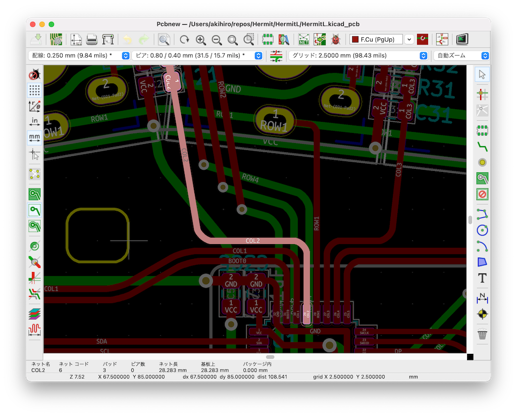
This way, the wiring is parallel to each part and looks roundy at corners.
The mechanical key switches chatter sometimes. Most DIY keyboards use software debouncing technique that comes with qmk (the standard keyboard firmware), where the key state (pressed or not) is examined twice with several milliseconds interval. So, the switch bounce is hidden usually. However, for the last two years, I experienced a couple of keys of my ErgoDash exhibited the chattering only in a specific season, i.e., in July or August in Japan. I guess the software debounce might not be enough when it is very hot and super humid. I've therefore added debounce RC for each column lines:
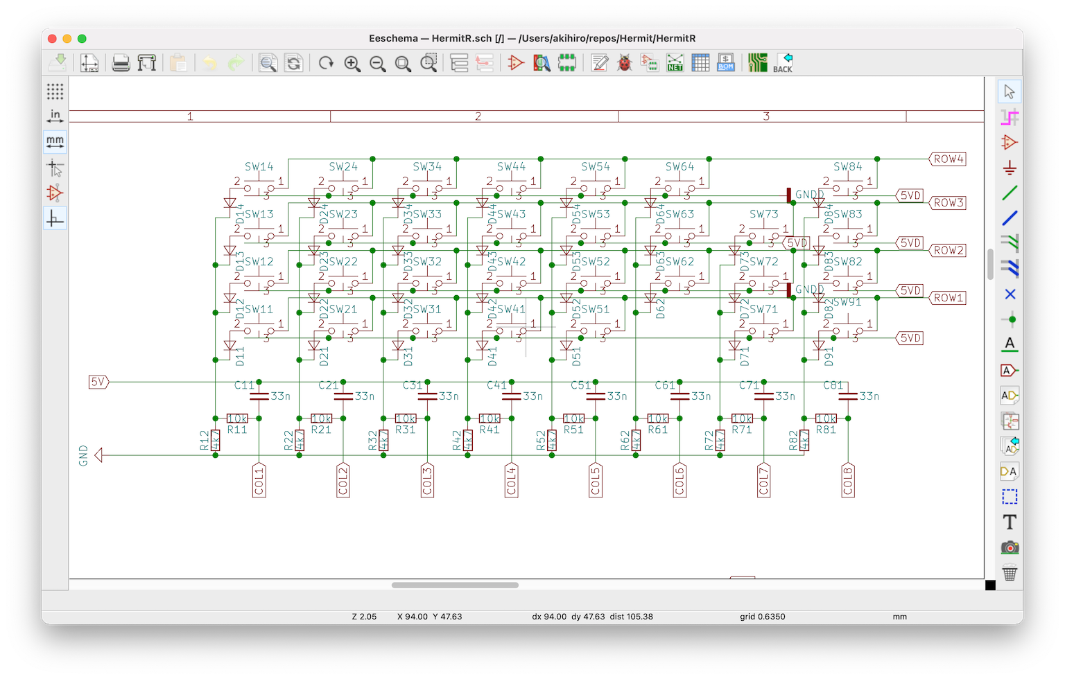
I will check if this will actually contribute to reduce the switch bounce in the next summer!
For more information on hardware debounce, please refer to articles such as Ultimate Guide to Switch Debounce (Part 3)
In Zoea PCB, it was useful to use hexagonal hole for spacers to keep them fixed: they won't rotate when tightening screws from the top and the bottom plates. However, I needed to carefully choose the hexagon radius and the radius of the hexagon corners taking into account the endmill diameter. So, this time, I used rectangular holes for the same purpose. I didn't have to consider much about the radius of the rectangle corners because any value would be fine with hexagon.
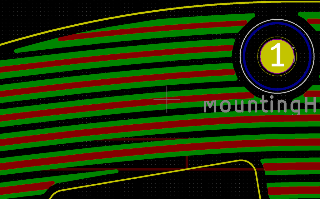
I wanted to fill the surface of the top and the bottom plates with some design other than just nothing. I'm not an artsy person at all, so I decided to draw simple stripes on them that curve along with the key switch angles. The problem was that, how to end the stripe lines at the boundary of the board, screw holes, and of course the key switch holes. I didn't want that to happen all of a sudden abruptly.
So, I figured out a way to end lines just before the boundaries:
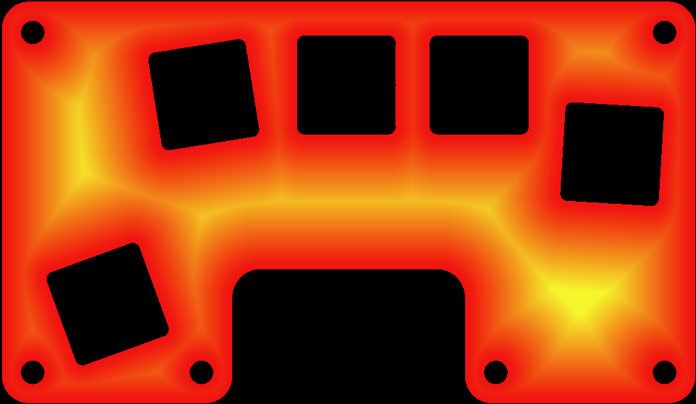
Then, you will get the distance from the boundaries. It would be easier to end lines nicely at the boundaries: if it is near the boundary, you can use the distance value to find where to end the line.
The following figures are from Zoea top layer. First, the distance transform.
The final stripes on PCB. The thickness is reversed on its front and back.
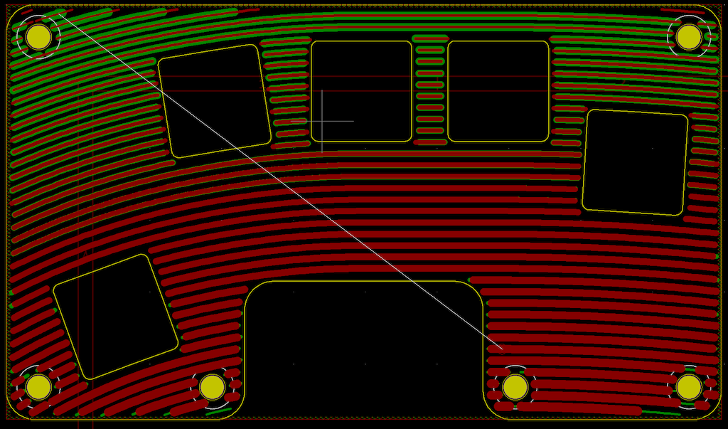
It looked ok that time, however, I wanted to get closer to the edge this time... So, divided thick lines into a multiple of thin lines:
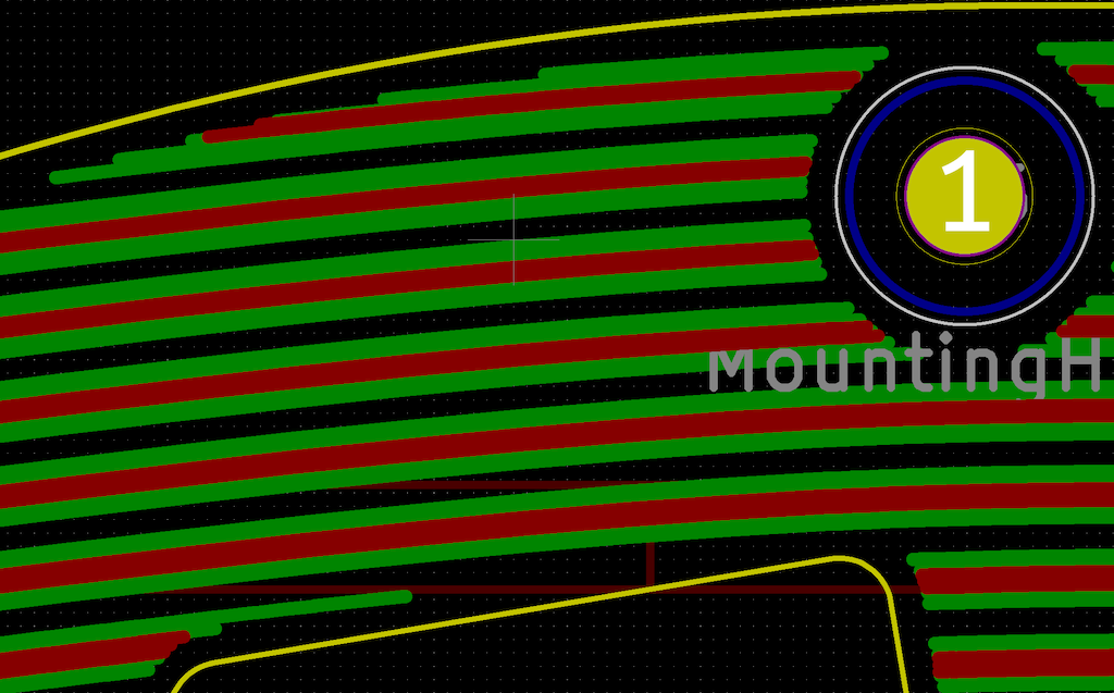
and then, drew vertical / slant lines that connect the ends of thin horizontal lines:
For my studying of embedded programming, I wrote the firmware from scratch instead of using qmk.
One thing I was thinking about qmk was register_code() and unregister_code() functions: these are used everywhere to send keycodes in the chain of processing. However, since they send keycodes immediately, there is no room to to do more processing on the processed keycodes in the middle of the chain.
Of course, there are pros and cons. But I wanted to try a stream structure, where each keycode processor is connected with FIFOs one after another to allow for successive processing. Also, only one HID report will be prepared in the big loop that runs every 2ms.
A difficult part is the estimation of the required size for each FIFO. If the FIFO size is too short, a processor in the chain cannot output anything and the entire stream would get stuck.
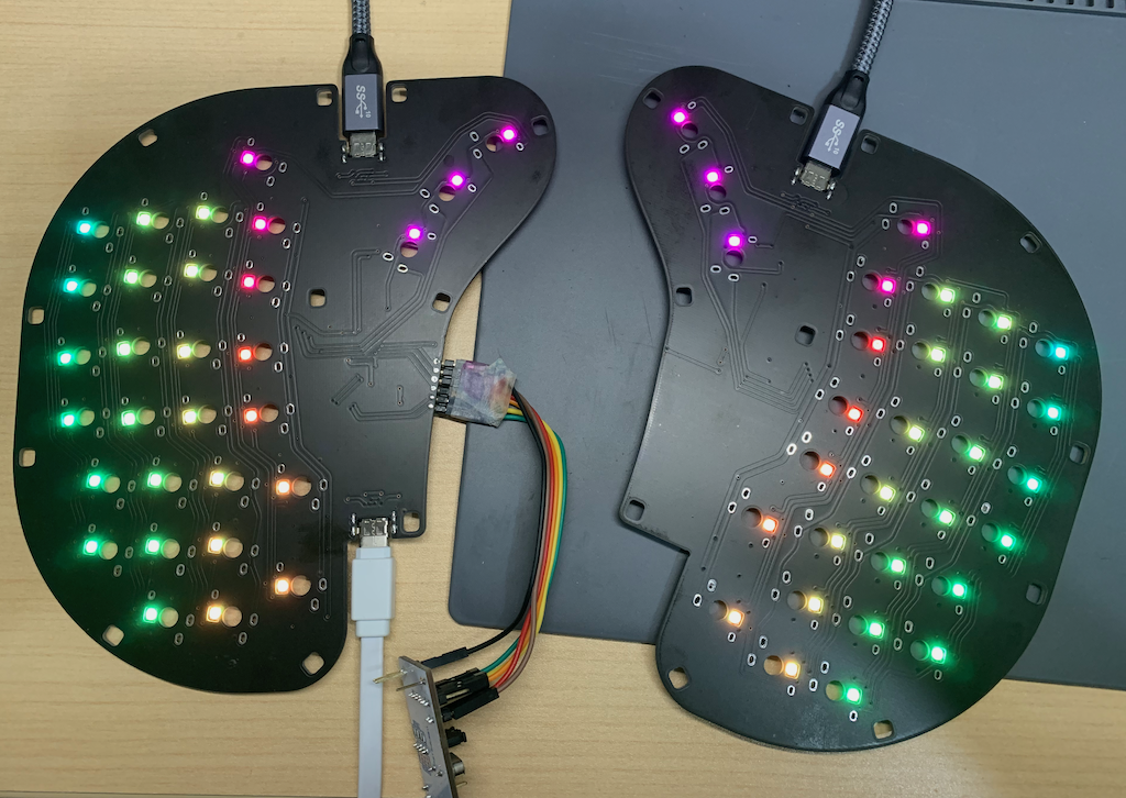
At first, I placed LC8822-2020 on the key switch side of PCB. They are good since they have separate data and clock lines (total 6 lines). However, I noticed later that when they got broken, it is difficult to replace them because key switches are soldered above them.
Then, I decided to use SK6812-MINI-E, which is commonly used in DIY keyboards. It has only one line for both data and clock, so it needs strict timing to send data. There are 60 keys on Hermit, so that it takes 2ms to send series of data for all of them at once. As 2ms felt too long, I split them to left and right half, and reduced the duration of interrupt-disabled periods to 1ms each.
I have been using Emacs key-binding for years. There are ways to emulate it in a software manner on Windows, but what if it is inside a keyboard itself?
Although the current implementation needs tap & hold for single press of CTRL and ALT, other than that, it is working nicely!
At first, the code bloated with STM32 HAL USB library and printf (for debugging purpose) to more than 20KB. However, thanks to STM32 LL library and the following libraries:
even after implemented RGB effects and Emacs translations, the current code size is:
namely, only the half of STM32F042 capacity (32KB/6KB) is used.
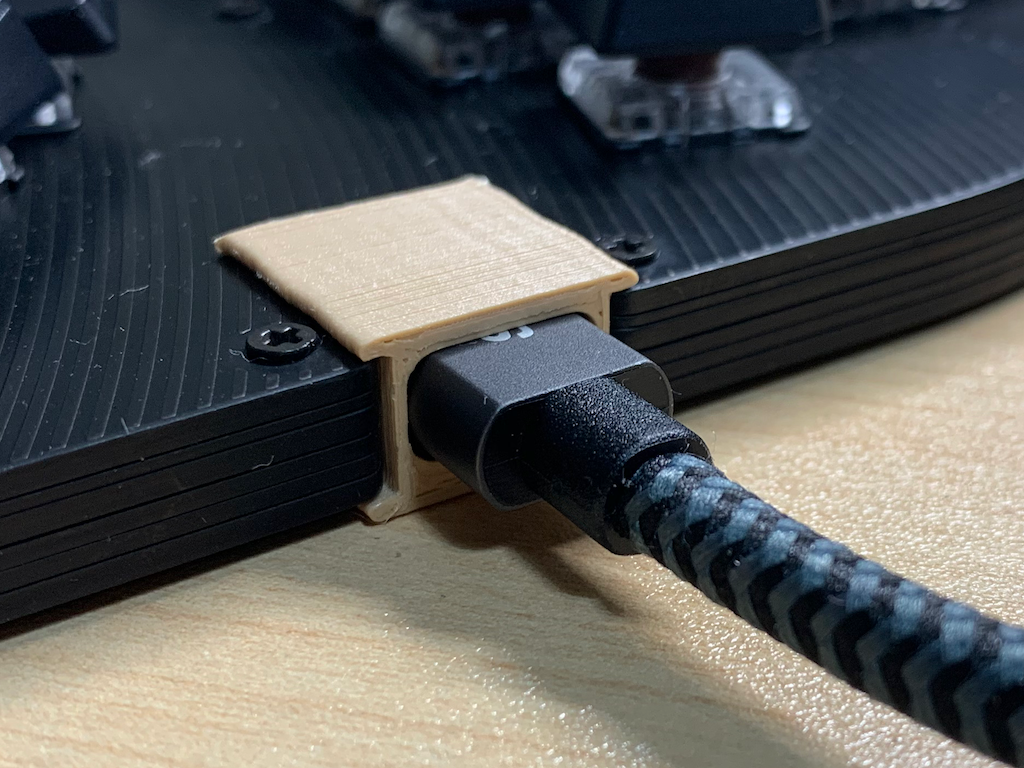
For USB Type-C connectors, I gave up using the full 24-pin type due to the lack of my ability to solder them on PCB. Instead, 16-pin type is used, where I2C is sent over D+/D- and LED signal is sent over SBU1/2. Although other USB3.0 signal lines are not used at all, only because SBU1/2 is used, "full spec" Type-C cable is required to connect left and right. They are thick in general and their stiffness gives strong forces on USB connectors. So, I printed a simple-extrusion-work cable connector holder for them. They need to be printed for each connector shape, but fit well and the cables are firmly attached to the keyboard.

| Qty | Value | Footprint | References |
|---|---|---|---|
| 3 | 0.1uF | Capacitor_SMD:C_0805_2012Metric_Pad1.15x1.40mm_HandSolder | C3, C5, C9 |
| 2 | 1uF | Capacitor_SMD:C_0805_2012Metric_Pad1.15x1.40mm_HandSolder | C1, C8 |
| 2 | 22 | Resistor_SMD:R_0805_2012Metric_Pad1.15x1.40mm_HandSolder | R6, R7 |
| 2 | 2K2 | Resistor_SMD:R_0805_2012Metric_Pad1.15x1.40mm_HandSolder | R4, R5 |
| 2 | 4.7uF | Capacitor_SMD:C_0805_2012Metric_Pad1.15x1.40mm_HandSolder | C4, C6 |
| 2 | 5k1 | Resistor_SMD:R_0805_2012Metric_Pad1.15x1.40mm_HandSolder | R8, R9 |
| 1 | 0.01uF | Capacitor_SMD:C_0805_2012Metric_Pad1.15x1.40mm_HandSolder | C7 |
| 1 | 10K | Resistor_SMD:R_0805_2012Metric_Pad1.15x1.40mm_HandSolder | R3 |
| 1 | 10uF | Capacitor_SMD:C_0805_2012Metric_Pad1.15x1.40mm_HandSolder | C2 |
| 1 | 1K5 | Resistor_SMD:R_0805_2012Metric_Pad1.15x1.40mm_HandSolder | R1 |
| 1 | 330 | Resistor_SMD:R_0805_2012Metric_Pad1.15x1.40mm_HandSolder | R2 |
| 1 | AP7333 | key-parts:AP7333 | U2 |
| 1 | BLM21 | Inductor_SMD:L_0805_2012Metric_Pad1.15x1.40mm_HandSolder | L1 |
| 1 | Conn_01x03 | key-parts:PinHeader_1x03_P2.54mm_Vertical | J3 |
| 1 | Conn_01x07 | key-parts:PinHeader_1x07_P2.54mm_Vertical | J2 |
| 1 | Conn_01x08 | key-parts:PinHeader_1x08_P2.54mm_Vertical | J1 |
| 1 | LED | Diode_SMD:D_0805_2012Metric_Pad1.15x1.40mm_HandSolder | D2 |
| 1 | PW_LED | Diode_SMD:D_0805_2012Metric_Pad1.15x1.40mm_HandSolder | D1 |
| 1 | Polyfuse | Fuse:Fuse_0805_2012Metric_Pad1.15x1.40mm_HandSolder | F1 |
| 1 | SK6812-2020 | key-parts:WS2812B_2020_Vertical | D3 |
| 1 | STM32F042K6Tx | Package_QFP:LQFP-32_7x7mm_P0.8mm | U1 |
| 1 | SW_Push | key-parts:SW_SMD_5x3 | SW1 |
| 1 | USB_C_Receptacle_USB2.0 | key-parts:USB_C_Receptacle_Neltron_5077CR | J4 |


google/mozc-devices
Circuit diagrams and firmware source code for Gboard DIY keyboards


VoronDesign/Voron-Hardware
Cool Hardware designed by the Voron Design group

hoglet67/RGBtoHDMI
Bare-metal Raspberry Pi project that provides pixel-perfect sampling of Retro Computer RGB/YUV video and conversion to HDMI

tenderlove/initial-v
It's a BMW shifter converted to a Bluetooth Keyboard that you use with Vim

hackclub/OnBoard
💡 Join 1,000 teenagers and make your first PCB with a $100 grant!


It measures 24.8 × 17.8 mm and has 2 copper layers, 1.6 mm thick.
30 parts. The full list of its parts is on this page, with links to each part's symbol and footprint where PCBKit's library has them.
From the orihikarna/Hermit repository on GitHub, at the commit this page was made from: the board is stm32tiny/stm32tiny.kicad_pcb. PCBKit opens the board in the browser, with nothing to install.
Its repository publishes it under the CC0-1.0 licence: you may reuse it on that licence's terms (keep the author's notice, and for a copyleft licence share your changes alike).