2 layers15.2 × 29.2 mm
Driver BreakoutBoard
opensourceimaging/cosi-measure
Open source 3D multipurpose measurement system with submillimeter fidelity and first application in magnetic resonance imaging
14 parts34CERN-OHL-W-2.0

 opensourceimaging/cosi-measure34
Open source 3D multipurpose measurement system with submillimeter fidelity and first application in magnetic resonance imaging
Endstop Levelshifter is an open-source printed circuit board by opensourceimaging, from the opensourceimaging/cosi-measure repository on GitHub, published under the CERN-OHL-W-2.0 licence. It is a 2-layer board of 26.4 × 21.8 mm with 6 parts on 17 nets, routed with 81 tracks and 13 vias.
Its parts include 4 connectors, 1 capacitor and 1 IC. It belongs with the interfaces and adapters boards of this library.
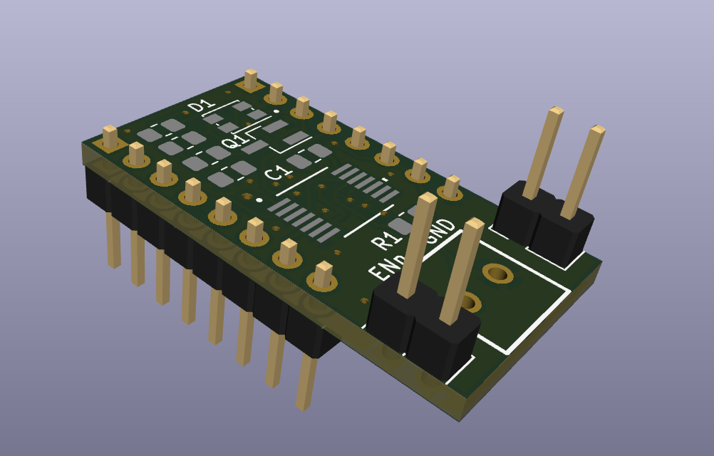
This breakoutboard can be placed to the motor driver slots into the Rumba32 board. It is useful for wiring the step, direction and enable pins via the motor connector to external motor drivers. In addition it supports an easy way of integrating a drive-enable functionality.
There can be current on the drives, if
Many 3D-printing firmwares are not designed for switching off the drives completly while executing a G-code file. But COSI-Measure is meant to perform magnetic measurements, so it must not disturb the measurements with noisy motor currents while performing a measurement.
A convenient workaround for Klipper is to switch on and off some extra GPIO Pins, that are wired to the hardware-enable-logic. In case you are doing something different and you do not need this feature, feel free to ignore it. Default of these Pins is low, which is also the enabled state. For details about it see the printer.cfg file line 275-317. The drives can be enabled and disabled with g-code macros while keeping the homing active.
The NPN-ok-signal from the emergency stop relais can be daisy-chained with standard 2.54 mm jumpers to the next breakout board.
The enable input of the motordriver is not meant for a safe-torque-off function (emergency stop). Safe-torque-off is implemented in hardware (mechanical relais, contactors etc.), see schematics. Anyway, to prevent driver malfunction the driver will be disabled with semiconductor only circuits before the power supply of the driver will be disconnected. The delay is coming from the slower reaction of mechanical contactors and relais, so no dedicated timing module is needed.
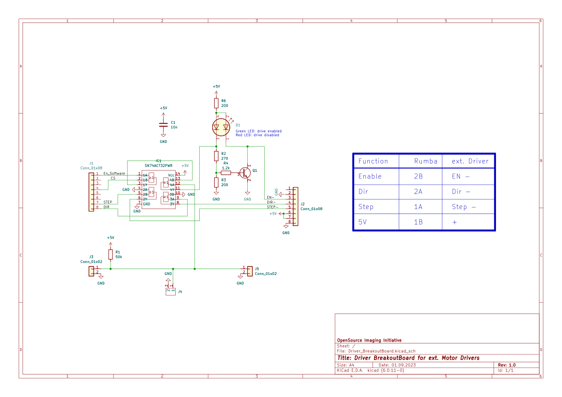
This Bill-of-Materials is for 1 breakout board only. You need one breakout board for each motor with external motor drivers, usually 3 in total (depending to your setup).
The STEPPER_DRIVER_LOGIC jumper (see picture below) selects the logic voltage supplied to all stepper driver
sockets. By default, it is configured so that 3.3V is supplied to the stepper drivers. However, since the external motor drivers need 5 V, the track between the centre and 3V pad should be cut, and a solder joint placed over the 5V and centre pad.

(picture and parts of the text above borrowed from https://github.com/Aus3D/RUMBA32/blob/master/Resources/Manual/RUMBA32%20V1.1%20User%20Manual%20-%20REV%20A.pdf, License: GPLv2)
Set the jumpers beneath the breakoutboards as seen in the picture below (blue):
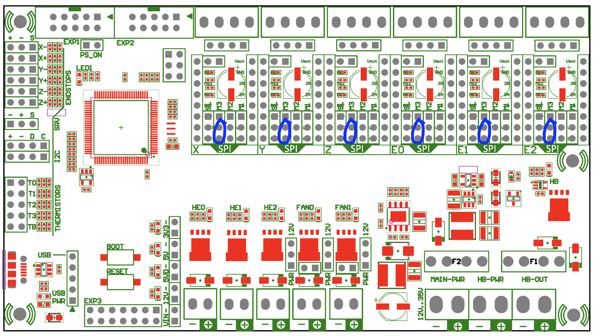
(Picture borrowed and modified from https://github.com/Aus3D/RUMBA32?tab=readme-ov-file, License: GPLv2)
These jumpers are connecting some GPIO-Pins to the enable logic of this breakout board.
| Qty | Value | Footprint | References |
|---|---|---|---|
| 1 | 10n | Capacitor_SMD:C_0805_2012Metric_Pad1.18x1.45mm_HandSolder | C1 |
| 1 | 74HC4050PW,118 | Package_SO:TSSOP-16_4.4x5mm_P0.65mm | IC1 |
| 1 | Conn_01x02 | Connector_PinHeader_2.54mm:PinHeader_1x02_P2.54mm_Horizontal | J4 |
| 1 | Conn_01x03 | Connector_PinSocket_2.54mm:PinSocket_1x03_P2.54mm_Vertical | J3 |
| 1 | Conn_01x05 | Connector_PinSocket_2.54mm:PinSocket_1x05_P2.54mm_Vertical | J2 |
| 1 | Conn_01x08 | custom_parts:691210910008 | J1 |
opensourceimaging/cosi-measure
Open source 3D multipurpose measurement system with submillimeter fidelity and first application in magnetic resonance imaging

byrantech/laptop
anyon_e, a highly integrated, high end, open source laptop. Attempt the impossible.


Jcparkyn/dpoint
Open-source digital stylus using camera tracking and inertial measurements

VoronDesign/Voron-Hardware
Cool Hardware designed by the Voron Design group

hoglet67/RGBtoHDMI
Bare-metal Raspberry Pi project that provides pixel-perfect sampling of Retro Computer RGB/YUV video and conversion to HDMI

hackclub/OnBoard
💡 Join 1,000 teenagers and make your first PCB with a $100 grant!

Luos-io/luos_engine
Open-source and real-time orchestrator for cyber-physical-systems, to easily design, test and deploy embedded applications and digital twins.

It measures 26.4 × 21.8 mm and has 2 copper layers, 1.6 mm thick.
6 parts. The full list of its parts is on this page, with links to each part's symbol and footprint where PCBKit's library has them.
From the opensourceimaging/cosi-measure repository on GitHub, at the commit this page was made from: the board is Electronics/electronic cabinet/Rumba32/Endstop_Levelshifter/Endstop_Levelshifter/Endstop_Levelshifter.kicad_pcb and its schematic Electronics/electronic cabinet/Rumba32/Driver_BreakoutBoard/Driver_BreakoutBoard.kicad_sch. PCBKit opens the board in the browser, with nothing to install.
Its repository publishes it under the CERN-OHL-W-2.0 licence: you may reuse it on that licence's terms (keep the author's notice, and for a copyleft licence share your changes alike).