4 layers90 × 60 mm
Better lamp controller
super-cow-powers/better-lamp-controller
A custom lamp controller with audio, controlled with an RP2040
103 partsBSD-3-Clause

 openpoenode/breakoutboard
Development board exposing all module features
Breakoutboard is an open-source printed circuit board by openpoenode, from the openpoenode/breakoutboard repository on GitHub, published under the CERN-OHL-W-2.0 licence. It is a 4-layer board of 74 × 55 mm with 58 parts on 71 nets, routed with 528 tracks and 63 vias.
It is built around the LMR33620BDDA, 10129381-906001BLF and GDH06S04, with the IN-P55QDTRGBW, PJ-063AH and RJHSE-5381 among its other parts. Its parts include 19 resistors, 12 capacitors, 11 connectors, 3 diodes and 3 switches. It belongs with the microcontroller boards boards of this library.


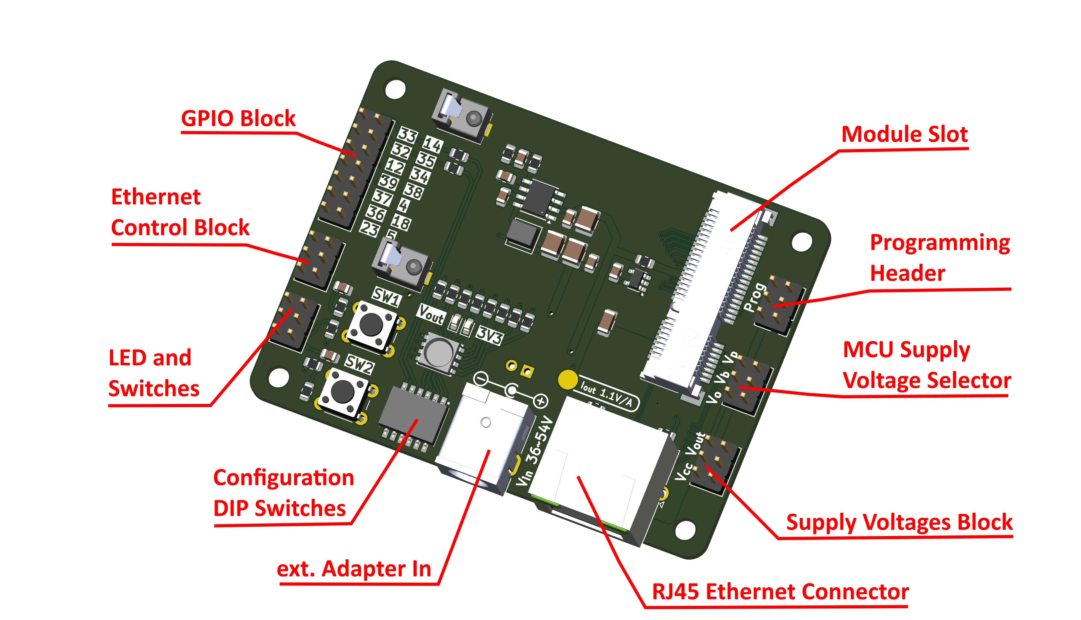
The Breakout Board carrier is designed to let developers explore the full feature set of the openPoeNode module before committing to a custom carrier design. It includes a range of practical features to simplify testing, evaluation, and firmware debugging.
The Breakout Board provides a single slot for an openPoeNode module with any supported output voltage. An onboard DC/DC converter is included to step down 5V module output to 3.3V for MCU supply.
The MCU section can be powered from one of three sources:
Select the desired source by placing a jumper cap on the corresponding pins.
Although the module includes overvoltage protection, avoid supplying 5V directly to the MCU section.
When powering the board via an external programmer, ensure it can provide sufficient current. Insufficient current may cause unstable behavior during programming (e.g., flash writes failing due to brownouts). If this occurs, use an external power adapter and select Vbuck as the supply source.
Connector for an external programmer or debugger. The pinout matches the ESP-Prog board from Espressif.
All module GPIOs are broken out to this header for general-purpose use. Pin numbering follows the ESP32-D0WD-V3 datasheet.
Three GPIOs are required to control the Ethernet interface (GPIO2 / GPIO13 / GPIO15). These are routed next to the corresponding MDC / MDIO / Enable pins.
The Breakout Board includes two tactile switches and one RGBW LED for quick testing.
A 6-position DIP switch enables convenient hardware configuration during development:
I²C pull-ups (GPIO32 / GPIO33)
Power load resistors
Power indicators
If PoE is unavailable or needs to be overridden, the board can be powered using an external 36–54V DC source.
Provides power outputs for external devices (e.g., sensors):
Ensure total consumption remains within the DC/DC converter limits:
For advanced use cases, raw PoE input voltage is available for external DC/DC converters.
⚠️ This connector is not populated by default and should be used with caution.
An onboard current monitor IC helps track power consumption and stay within PoE and DC/DC converter limits (0.44W < P < 7W).
| Qty | Value | Footprint | References |
|---|---|---|---|
| 5 | 100nF | Capacitor_SMD:C_0805_2012Metric | C5, C9, C10, C11, C12 |
| 5 | 10129381-906001BLF | Connector_PinHeader_2.54mm:PinHeader_2x03_P2.54mm_Vertical | J2, J3, J4, J6, J10 |
| 4 | 270R | Resistor_SMD:R_0805_2012Metric | R1, R2, R17, R18 |
| 4 | MountingHole | MountingHole:MountingHole_3.2mm_M3 | H1, H2, H3, H4 |
| 3 | 56R | Resistor_SMD:R_0805_2012Metric | R7, R14, R15 |
| 2 | 10K | Resistor_SMD:R_0805_2012Metric | R11, R13 |
| 2 | 1K | Resistor_SMD:R_0805_2012Metric | R10, R12 |
| 2 | 22uF | Capacitor_SMD:C_1210_3225Metric | C7, C8 |
| 2 | 2K2 | Resistor_SMD:R_0805_2012Metric | R3, R5 |
| 2 | LOGO | LOGO | G***, G*** |
| 2 | Red | LED_SMD:LED_0603_1608Metric | D4, D5 |
| 2 | TS02-66-43 | Button_Switch_THT:SW_PUSH_6mm_H4.3mm | SW1, SW2 |
| 1 | 0R022 | Resistor_SMD:R_0805_2012Metric | R19 |
| 1 | 100K | Resistor_SMD:R_0805_2012Metric | R8 |
| 1 | 100R 0.5W | Resistor_SMD:R_0805_2012Metric | R4 |
| 1 | 10129381-914001BLF | Connector_PinHeader_2.54mm:PinHeader_2x07_P2.54mm_Vertical | J9 |
| 1 | 10uF | Capacitor_SMD:C_1210_3225Metric | C2 |
| 1 | 180R | Resistor_SMD:R_0805_2012Metric | R16 |
| 1 | 1uF | Capacitor_SMD:C_0805_2012Metric | C4 |
| 1 | 2200pF 2kV | Capacitor_SMD:C_1206_3216Metric | C1 |
| 1 | 220nF | Capacitor_SMD:C_0805_2012Metric | C3 |
| 1 | 3.3uH | Inductor_SMD:L_Wuerth_MAPI-4030 | L1 |
| 1 | 33pF | Capacitor_SMD:C_0805_2012Metric | C6 |
| 1 | 43K2 | Resistor_SMD:R_0805_2012Metric | R9 |
| 1 | 56R 0.5W | Resistor_SMD:R_0805_2012Metric | R6 |
| 1 | GDH06S04 | Project:GDH06S04 | SW4 |
| 1 | IN-P55QDTRGBW | Project:INP55QDTRGBW | D3 |
| 1 | INA180A2 | Package_TO_SOT_SMD:SOT-23-5 | U1 |
| 1 | LMR33620BDDA | Package_SO:Texas_HSOP-8-1EP_3.9x4.9mm_P1.27mm_ThermalVias | U2 |
| 1 | PJ-063AH | Connector_BarrelJack:BarrelJack_CUI_PJ-063AH_Horizontal | J1 |
| 1 | RJHSE-5381 | Connector_RJ:RJ45_Amphenol_RJHSE538X | J5 |
| 1 | TestPoint | TestPoint:TestPoint_Pad_D3.0mm | TP1 |
| 1 | ~ | Connector_PinHeader_2.54mm:PinHeader_1x02_P2.54mm_Vertical | J11 |
| 1 | ~ | Modul:119A-LATCH-80 | J8 |
| 1 | ~ | Modul:119A-80A00-R02 | J7 |
It measures 74 × 55 mm and has 4 copper layers, 1.58 mm thick.
58 parts, built around the LMR33620BDDA, 10129381-906001BLF, GDH06S04 and IN-P55QDTRGBW. The full list of its parts is on this page, with links to each part's symbol and footprint where PCBKit's library has them.
From the openpoenode/breakoutboard repository on GitHub, at the commit this page was made from: the board is BreakoutBoard.kicad_pcb and its schematic BreakoutBoard.kicad_sch. PCBKit opens the board in the browser, with nothing to install.
Its repository publishes it under the CERN-OHL-W-2.0 licence: you may reuse it on that licence's terms (keep the author's notice, and for a copyleft licence share your changes alike).
super-cow-powers/better-lamp-controller
A custom lamp controller with audio, controlled with an RP2040

Fabmicro-LLC/Karnix_ASB-254
Karnaugh Interactive Extendable ASIC Simulation Board AKA Karnix ASB-254

Accessibilita/USB-HID-Module-Hat
Raspberry Pi Hat that adds RS485 communication to Raspberry Pi 5 for interfacting with USB and Bluetooth HID Devices


Accessibilita/recline-controls
Hardware project for open source wheel chair recline control electronics

