2 layers65 × 25 mm

 OpenARDF/Arducon7
A transmitter controller for Amateur Radio Direction Finding (ARDF). Based on the Arduino Pro Mini.
Arducon is an open-source printed circuit board by OpenARDF, from the OpenARDF/Arducon repository on GitHub, published under the MIT licence. It is a 2-layer board of 83.5 × 45 mm with 114 parts on 83 nets, routed with 1,334 tracks and 303 vias.
It is built around the CD74HC4050M96, PE43712B and DS3231S#, with the LP2992AIM5-3.3, RV-8803-C7 and PN2222A among its other parts. Its parts include 13 resistors, 12 connectors, 11 diodes, 8 capacitors and 5 ICs. It belongs with the radio and wireless boards of this library.


Arducon is an Arduino-based ARDF transmitter controller for conducting Radio Orienteering (aka, Amateur Radio Direction-Finding - ARDF) competitions.
When connected to the audio output of an Amateur Radio handy-talky or similar receiver Arducon will decode Dual-Tone Multi Frequency (DTMF) tones that are used to configure and control Arducon.
When connected to the microphone input of an Amateur Radio handy-talky or similar transmitter Arducon will control the transmitter to cause it to send signals of the proper timing and format for regulation Radio Orienteering competitions. Arducon is suitable for controlling most 2m or 80m transmitters used for Radio Orienteering.
Consult the User Manual for more information on Arducon and its capabilities.
Use SerialSlinger to configure and update Arducon through its serial port without memorizing raw serial commands.
Pictured below are all the parts that comprise an Arducon. Put them together, then just add a power source (a 9V battery will do) and cables to the transmitter, and you've got a complete automated "fox" transmitter.
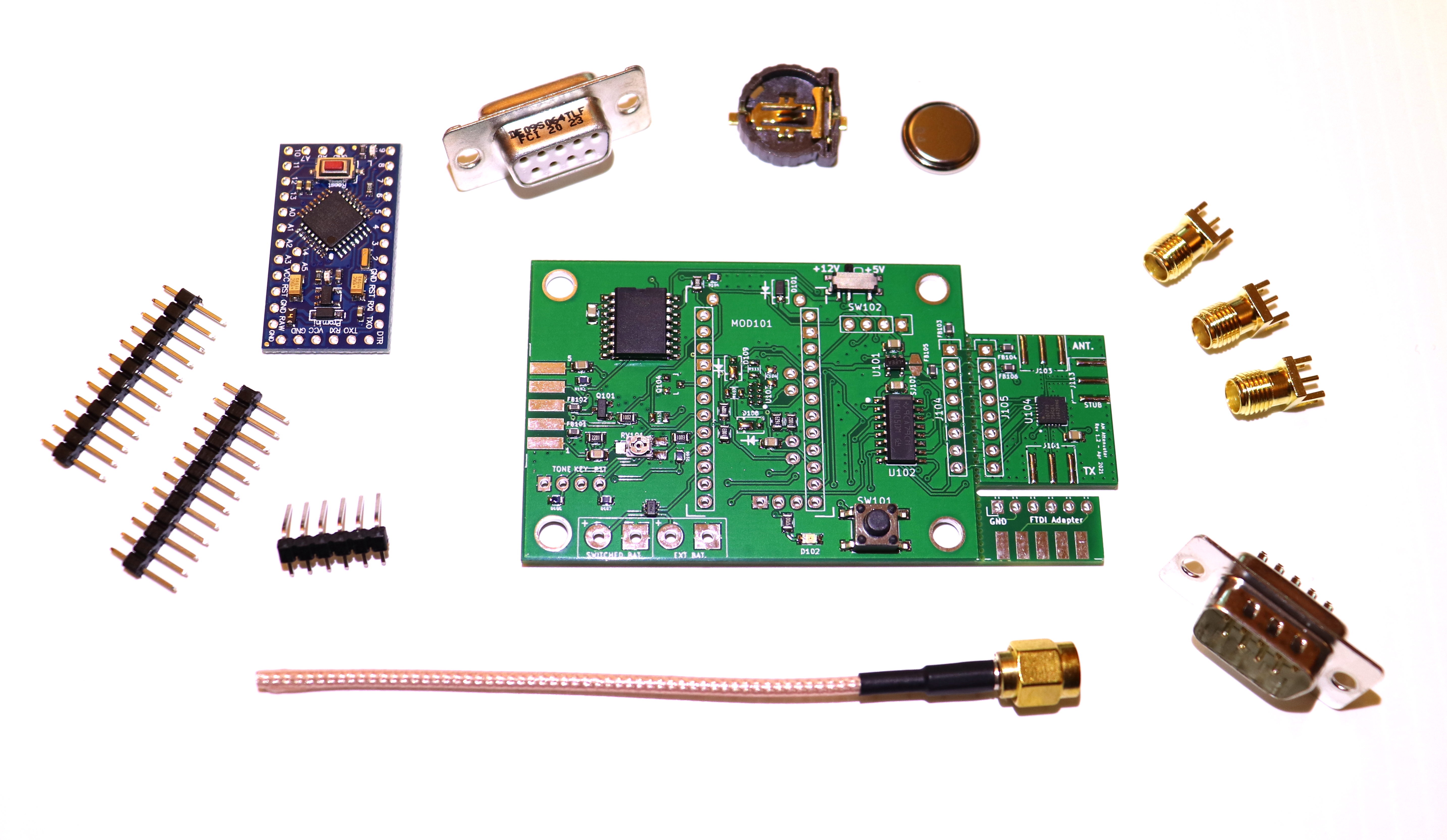
Want to change the hardware design, or modify the software? Everything you need is provided in the following folders:
KiCad
The KiCad folder holds files for generating the schematic, BOM, and PCB files using KiCad. On an OS X system the kicad directory should be placed in ~/Documents/GitHub/Arducon.
Software
The maintained firmware source lives under Software/AtmelStudio7/Arducon and targets an Arduino Pro Mini / ATmega328P using the Atmel Studio 7 project or the repo-owned CLI Release build scripts. Arduino IDE builds are no longer supported.
Use the CLI Release build for reproducible local builds:
powershell -ExecutionPolicy Bypass -File .\build-cli-release.ps1 -Clean
powershell -ExecutionPolicy Bypass -File .\compare-cli-release.ps1
Run host-side unit tests on macOS, Windows, or Linux with:
just host-unit-testsMicrochip/Atmel Studio 7 Release remains the cross-check path for now:
powershell -ExecutionPolicy Bypass -File .\build-firmware.ps1 -Configuration Release
powershell -ExecutionPolicy Bypass -File .\check-firmware-size.ps1 -Configuration Release
See BOOTLOADER_WORKFLOW.md for Optiboot provisioning, release packaging, fuse handling, and serial bootloader smoke tests.
See RELEASE_WORKFLOW.md for GitHub release publishing and version-number policy.
| Qty | Value | Footprint | References |
|---|---|---|---|
| 32 | NP_Thru_Hole_0.5mm | Mounting_Holes:NP_Thru_Hole_0.5mm | , , , , , , , , , , , , , , , +16 |
| 8 | SolderJumper_2_Open | Wire_Connections_Bridges:Solder-Jumper-NO-SMD-Pad_Small | SJ101, SJ102, SJ103, SJ104, SJ105, SJ106, SJ107, SJ108 |
| 6 | Ferrite_Bead_Small | Resistors_SMD:R_0603 | FB101, FB102, FB103, FB104, FB105, FB106 |
| 5 | 10k | Resistors_SMD:R_0805 | R103, R104, R108, R109, R111 |
| 5 | CG0603MLC-05LECT-ND | Resistors_SMD:R_0603 | D103, D104, D105, D106, D107 |
| 4 | 100nF | Capacitors_SMD:C_0805 | C103, C108, C109, C110 |
| 4 | 10uF | Capacitors_SMD:C_0805 | C101, C102, C104, C105 |
| 4 | MountingHole_4mm | Mounting_Holes:MountingHole_4mm_Outlined | 4mm thru, 4mm thru, 4mm thru, 4mm thru |
| 3 | MSS1P2L-M3/89A | Diodes_SMD:DO-219AD | D108, D109, D110 |
| 3 | PN2222A | TO_SOT_Packages_SMD:SOT-23 | Q101, Q103, Q104 |
| 2 | 100k | Resistors_SMD:R_0805 | R101, R106 |
| 2 | Conn_01x08 | Pin_Headers:Pin_Header_Straight_1x08 | J104, J105 |
| 2 | LED | LEDs:LED_0805 | D102, D102 |
| 2 | SPST | Buttons_Switches_SMD:PTS645SL50SMTR92 | SW101, SW101 |
| 2 | SolderJumper_3_Bridged12 | Wire_Connections_Bridges:Solder-Jumperx3-NC_1-2_SMD-Pad_Small | SJ109, SJ110 |
| 1 | 10 | Resistors_SMD:R_0805 | R110 |
| 1 | 10k | Potentiometers:Potentiometer_ST32ET_Handsolder | RV101 |
| 1 | 162k | Resistors_SMD:R_0805 | R107 |
| 1 | 1M | Resistors_SMD:R_0805 | R105 |
| 1 | 2.2k | Resistors_SMD:R_0805 | R102 |
| 1 | 210k | Resistors_SMD:R_0805 | R113 |
| 1 | 4.3V | Diodes_SMD:SOD-123 | D101 |
| 1 | 470 | Resistors_SMD:R_0805 | R114 |
| 1 | 5V/12V | Buttons_Switches_SMD:SW_SPDT_PCM12 | SW102 |
| 1 | Arduino Pro Mini (5V Version) | Modules:Arduino_Pro_Mini | MOD101 |
| 1 | CD74HC4050M96 | Housings_SOIC:SOIC-16_3.9x9.9mm_Pitch1.27mm | U102 |
| 1 | CR1220 | Oddities:BC501SM_CR1220_BAT_Handsolder | BT101 |
| 1 | Conn_01x04 | Pin_Headers:Pin_Header_Straight_1x04 | TP101 |
| 1 | Conn_01x06 | Pin_Headers:Pin_Header_Angled_1x06 | J112 |
| 1 | Controlled Power | Wire_Pads:SolderWirePad_2x_1-5mmDrill_Polarized | J108 |
| 1 | DB9 Female | Connect:DB9F_CI | J102 |
| 1 | DB9_Male | Connect:DB9F_CI | J111 |
| 1 | DS3231 | SMD_Packages:SO16 | U105 |
| 1 | External Power Source | Wire_Pads:SolderWirePad_2x_1-5mmDrill_Polarized | J107 |
| 1 | ISP/PDI | Pin_Headers:SM_Pin_Header_Straight_2x03 | P101 |
| 1 | LMN200 | TO_SOT_Packages_SMD:SOT-363-0.65 | Q102 |
| 1 | LP2992AIM5-3.3 | TO_SOT_Packages_SMD:SOT-23-5 | U101 |
| 1 | PE43712 | Housings_DFN_QFN:QFN-32-1EP_5x5mm_Pitch0.5mm | U104 |
| 1 | RV-8803-C7 | Oddities:RV-3028-C7 | U103 |
| 1 | To Antenna | Connect:CON-SMA-EDGE-S | J103 |
| 1 | To Radio | Connect:CON-SMA-EDGE-S | J101 |
| 1 | To Stub | Connect:CON-SMA-EDGE-S | J113 |
| 1 | Waveguide_50_ohms | Oddities:Waveguide_50_ohms | WG2 |
| 1 | Waveguide_T_50_ohms | Oddities:Waveguide_T_50_ohms | WG1 |
| 1 | Wiring | Pin_Headers:Pin_Header_Straight_1x08 | J106 |
It measures 83.5 × 45 mm and has 2 copper layers, 1.6 mm thick.
114 parts, built around the CD74HC4050M96, PE43712B, DS3231S# and LP2992AIM5-3.3. The full list of its parts is on this page, with links to each part's symbol and footprint where PCBKit's library has them.
From the OpenARDF/Arducon repository on GitHub, at the commit this page was made from: the board is kicad/Arducon.kicad_pcb and its schematic KiCad/Arducon.kicad_sch. PCBKit opens the board in the browser, with nothing to install.
Its repository publishes it under the MIT licence: you may reuse it on that licence's terms (keep the author's notice, and for a copyleft licence share your changes alike).


Ali-M0/EDrive
A closed-loop control system designed to stack with stepper motors and provide real-time feedback using a magnetic encoder.


TheUnknownAlias/betr_kicad_resources
This repository contains shared KiCad symbols and footprints for our projects.

dumaiss/pBITzPlatform
Code, documentation and schematics for the pBITz backplane and associated assets

touhidsiddiqueeraj-bit/Multi-Horizon-Hazard-Models-for-Battery-Failure-Prediction
This study extends an existing multi-horizon hazard classification framework—originally developed for NASA 18650 cells using Histogram-based Gradient Boosting (HGB)—to three additional datasets (CALCE LCO/CX2, Oxford…
