2 layers37.8 × 21.5 mm

 OnkarMore20/Robot_PCB
KiCad PCB design and schematic files for my robot project
Robot PCB is an open-source printed circuit board by OnkarMore20, from the OnkarMore20/Robot_PCB repository on GitHub. It is a 2-layer board of 58.3 × 78.8 mm with 17 parts on 34 nets, routed with 142 tracks and 13 vias.
It is built around the LM2596S-5.0 and LSM9DS1. Its parts include 12 connectors and 1 capacitor. It belongs with the robots and motor control boards of this library.


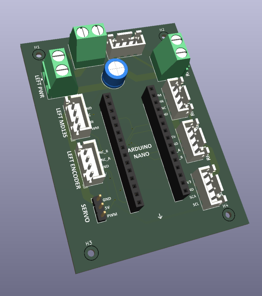
A custom PCB design for a robotics project, developed using KiCad.
📌 Overview
This repository contains the PCB layout, circuit schematic, and project files for the Robot PCB. The design files are maintained using Git and GitHub for version control and project documentation.
🛠️ Design Tools
🖥️ Project Files
| File | Description |
|---|---|
pcb.kicad_pcb | PCB layout and routing |
pcb.kicad_sch | Circuit schematic |
pcb.kicad_pro | Project configuration |
pcb.glb | 3D model |
DRC.rpt | Design Rule Check report |
ERC.rpt | Electrical Rule Check report |
📸 Design Preview
🚀 How to Open the Project
Author: Onkar More
| Qty | Value | Footprint | References |
|---|---|---|---|
| 4 | MountingHole | MountingHole:MountingHole_2.1mm | H1, H2, H3, H4 |
| 1 | 470uF | Capacitor_THT:C_Radial_D8.0mm_H7.0mm_P3.50mm | C1 |
| 1 | Battery XT60 | TerminalBlock_Phoenix:TerminalBlock_Phoenix_MKDS-1,5-2-5.08_1x02_P5.08mm_Horizontal | J1 |
| 1 | ENC_LEFT | Connector_JST:JST_XH_B4B-XH-A_1x04_P2.50mm_Vertical | J5 |
| 1 | ENC_RIGHT | Connector_JST:JST_XH_B4B-XH-A_1x04_P2.50mm_Vertical | J6 |
| 1 | LM2596 | Connector_JST:JST_XH_B4B-XH-A_1x04_P2.50mm_Vertical | J2 |
| 1 | LSM9DS1 | Connector_JST:JST_XH_B4B-XH-A_1x04_P2.50mm_Vertical | J8 |
| 1 | MD13S_LEFT | Connector_JST:JST_XH_B4B-XH-A_1x04_P2.50mm_Vertical | J3 |
| 1 | MD13S_LEFT_PWR | TerminalBlock_Phoenix:TerminalBlock_Phoenix_MKDS-1,5-2-5.08_1x02_P5.08mm_Horizontal | J9 |
| 1 | MD13S_RIGHT | Connector_JST:JST_XH_B4B-XH-A_1x04_P2.50mm_Vertical | J4 |
| 1 | MD13S_RIGHT_PWR | TerminalBlock_Phoenix:TerminalBlock_Phoenix_MKDS-1,5-2-5.08_1x02_P5.08mm_Horizontal | J10 |
| 1 | STEERING_SERVO | Connector_PinHeader_2.54mm:PinHeader_1x03_P2.54mm_Vertical | J7 |
| 1 | nano_left | Connector_PinSocket_2.54mm:PinSocket_1x15_P2.54mm_Vertical | J13 |
| 1 | nano_right | Connector_PinSocket_2.54mm:PinSocket_1x15_P2.54mm_Vertical | J14 |
It measures 58.3 × 78.8 mm and has 2 copper layers, 1.6 mm thick.
17 parts, built around the LM2596S-5.0 and LSM9DS1. The full list of its parts is on this page, with links to each part's symbol and footprint where PCBKit's library has them.
From the OnkarMore20/Robot_PCB repository on GitHub, at the commit this page was made from: the board is pcb/pcb.kicad_pcb and its schematic pcb/pcb.kicad_sch. PCBKit opens the board in the browser, with nothing to install.
Its repository states no licence, so its author keeps all rights: ask OnkarMore20 before reusing the design.

doppelgrau/esp32-f9p-io-board
An IO-PCB (two motor-driver/H-bridge, CAN, RS232, ADS1115, relay, ethernet, ardusimple f9p compatible connector) with an ESP32 for 12V power, three 15V tolerant analog inputs, three 5V tolerant inputs.


CosmicPi/CosmicPiV1.7PCB
PCB for Version 1.7 of the Cosmic Pi Hardware. Incremental changes from V1.6. This design is licensed under the CERN OHL V1.2

DasBasti/NokiaRetroFit
Retrofitting a Nokia 3210 with modern Processor


ybabs/H745FCS
Quadcopter Flight Controller based on the dual core STM32H745 Microcontroller