2 layers103 × 30.5 mm

 olxssa/perfusion_automation1
Design and implementation of an automated high-content screening cell perfusion system, including associated control software
Custom ffc is an open-source printed circuit board by olxssa, from the olxssa/perfusion_automation repository on GitHub. It is a 2-layer board of 99.5 × 89.5 mm with 9 parts on 9 nets, routed with 49 tracks and 0 vias.

Design and implementation of an automated high-content screening cell perfusion system, including associated control software
Here, the design, implementation and benchmarking of a fully integrated, modular screening platform for automated, multiplexed bath perfusion experiments is documented. The system was developed to provide reproducible and sample-friendly solution exchange for optical characterization of biosensors.
The platform consists of three primary systems: a modular fluorescence microscope, an automated bath perfusion add-on, and an integrated hardware and software control framework.
Using the software FreeCAD, the provided CAD files can be exported as .stl and 3D-printed using PLA, 15 % infill and 0.2 mm layer height. Alternatively, the files can be adapted to your liking.
In order to create a more elegant design for controlling the microvalves, a custom Flexible Printed Circuit (FPC) was designed using KiCAD in accordance with the information given by the company memetis. The microvalves are controlled via a constant-current source. The valves are all connected in series and can each be bypassed on the circuit board using a MOSFET, with a tap between the valve contacts. This allows individual valves to be removed from the current path and taken out of the control circuit.
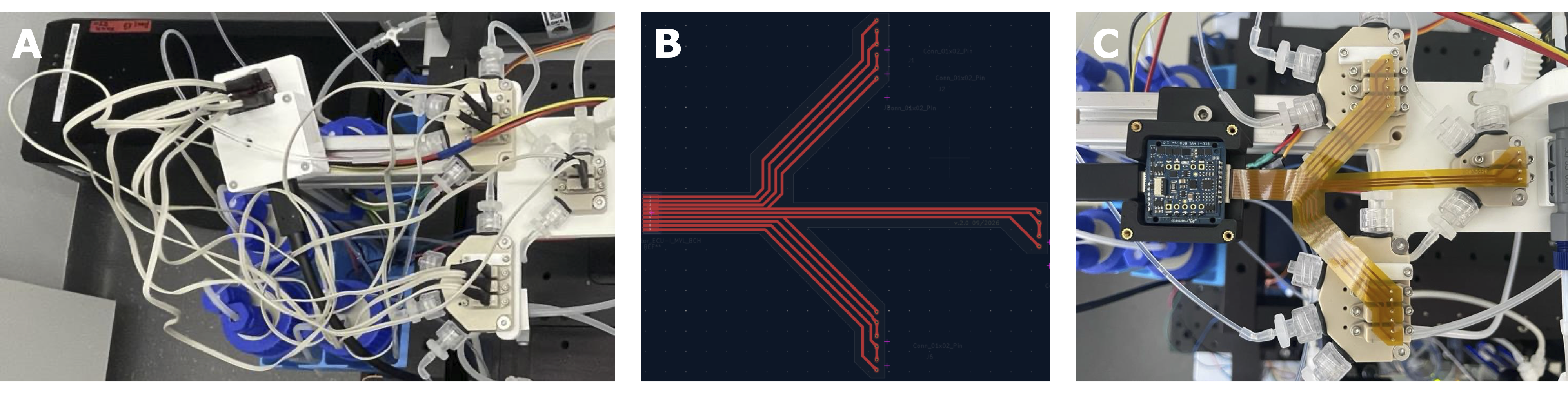
Custom-designed flexible printed circuit (FPC) for ECU-I 8CH and eight microvalves positioned on two 4-valve adapters and one 2-valve adapter. (A) Top-view of perfusion arm where 8 individual cables were connected to the controller adapter. (B) The PCB layer of the custom-designed FPC in KiCAD. (C) Top-view of the perfusion arm with the FPC.
Low-level hardware management is split between two microcontrollers and using the firmware rx_system.ino and tx_system.ino. High-level microscope hardware control is achieved via Pycro-Manager [1], which bridges the Python backend to a headless Java-based Micro-Manager [2] (v2.0.3) instance over port 4721. The Micro-Manager instance is created using the config file MMConfig.cfg.
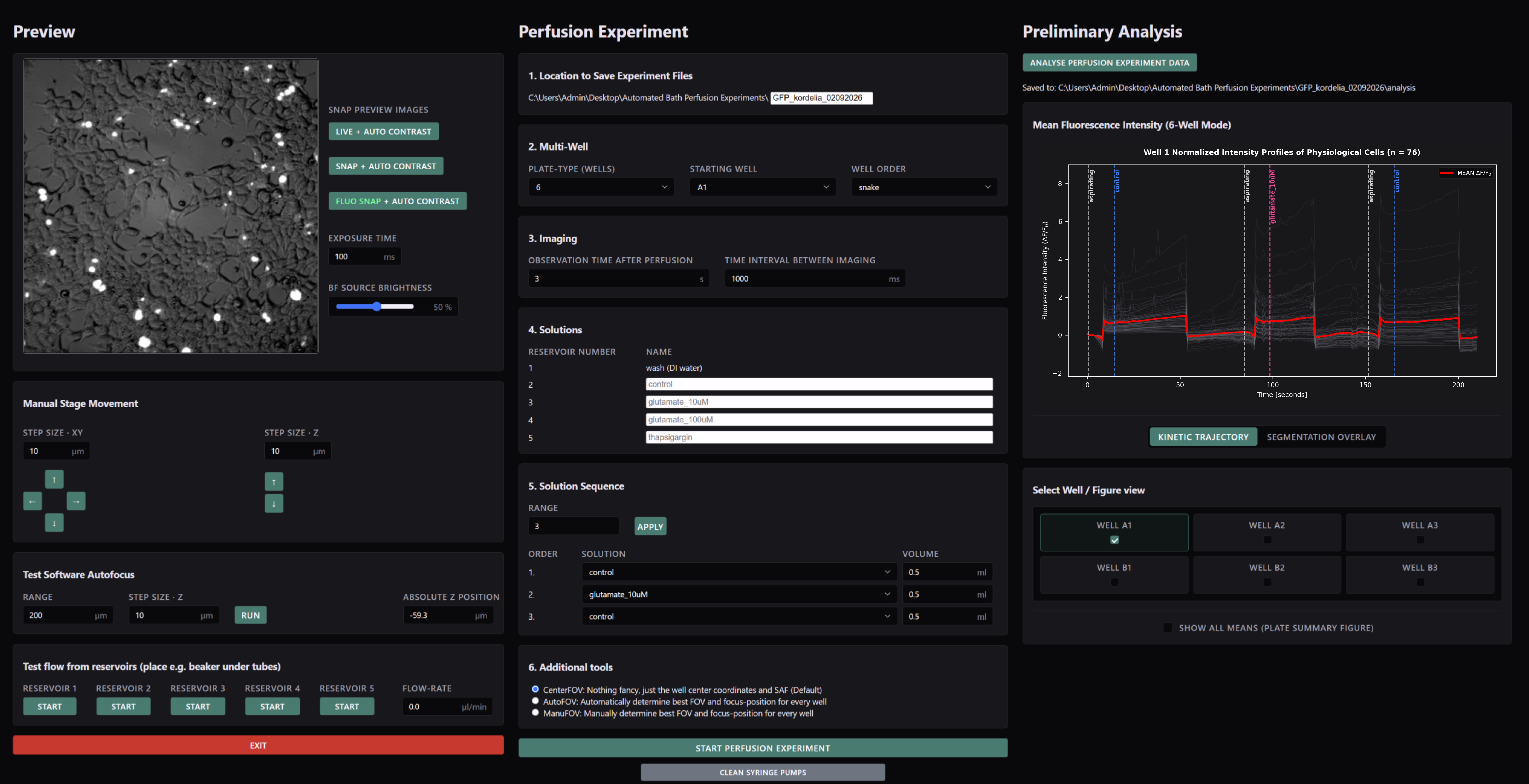
After the build, the setup can be controlled via a custom-developed web application called "Automated Bath Perfusion App". The web application serves as a single-page dashboard designed to organize all operational controls into three dedicated panels arranged from left to right:
The system's performance is validated by assessing pipetting procedures, demonstrating software autofocus stability and conducting automated multiplexed perfusion on cells expressing GFP and NEMO-based calcium sensors under agonist conditions.
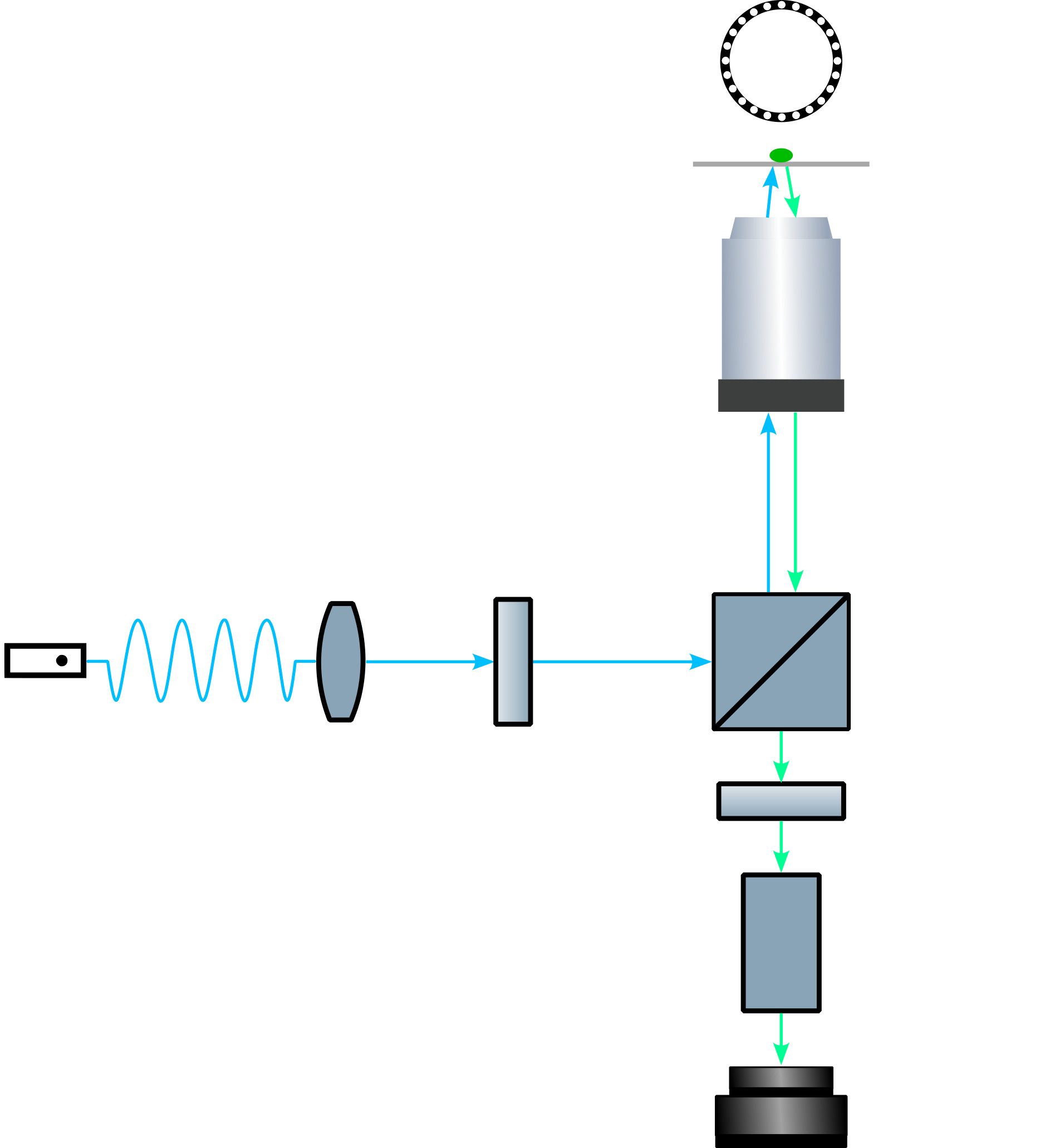
Schematic optical light path of the modular fluorescence microscope.
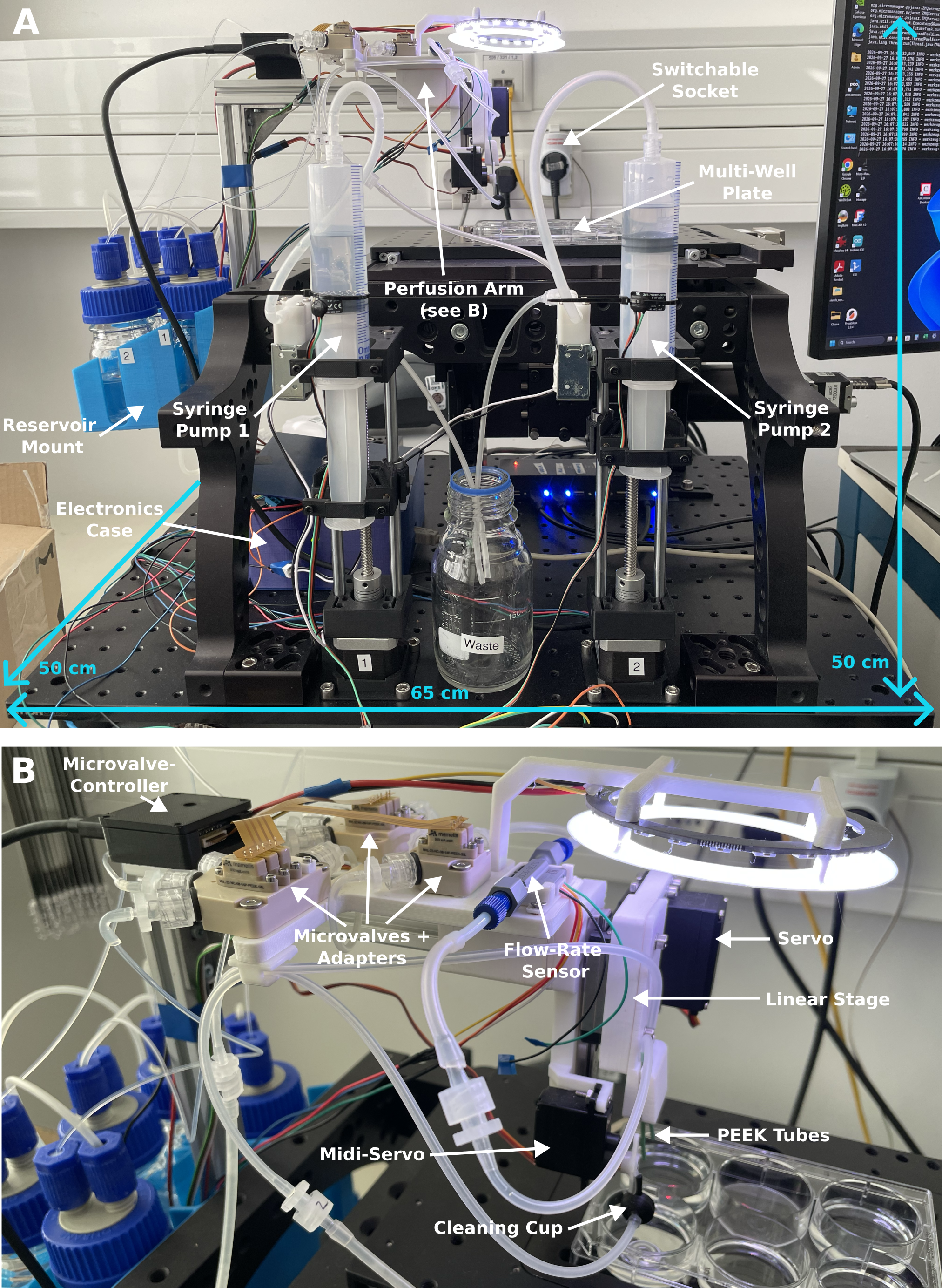
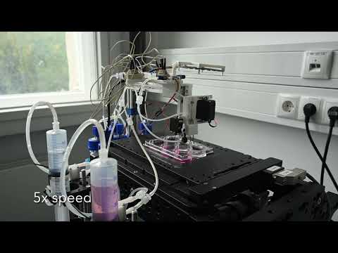
Implementation of the automated bath perfusion system. (A) The complete automated screening perfusion system integrated into the modular fluorescence microscope. (B) The perfusion arm responsible for movement of tubes into single wells and for the perfusion and aspiration of the desired solution.
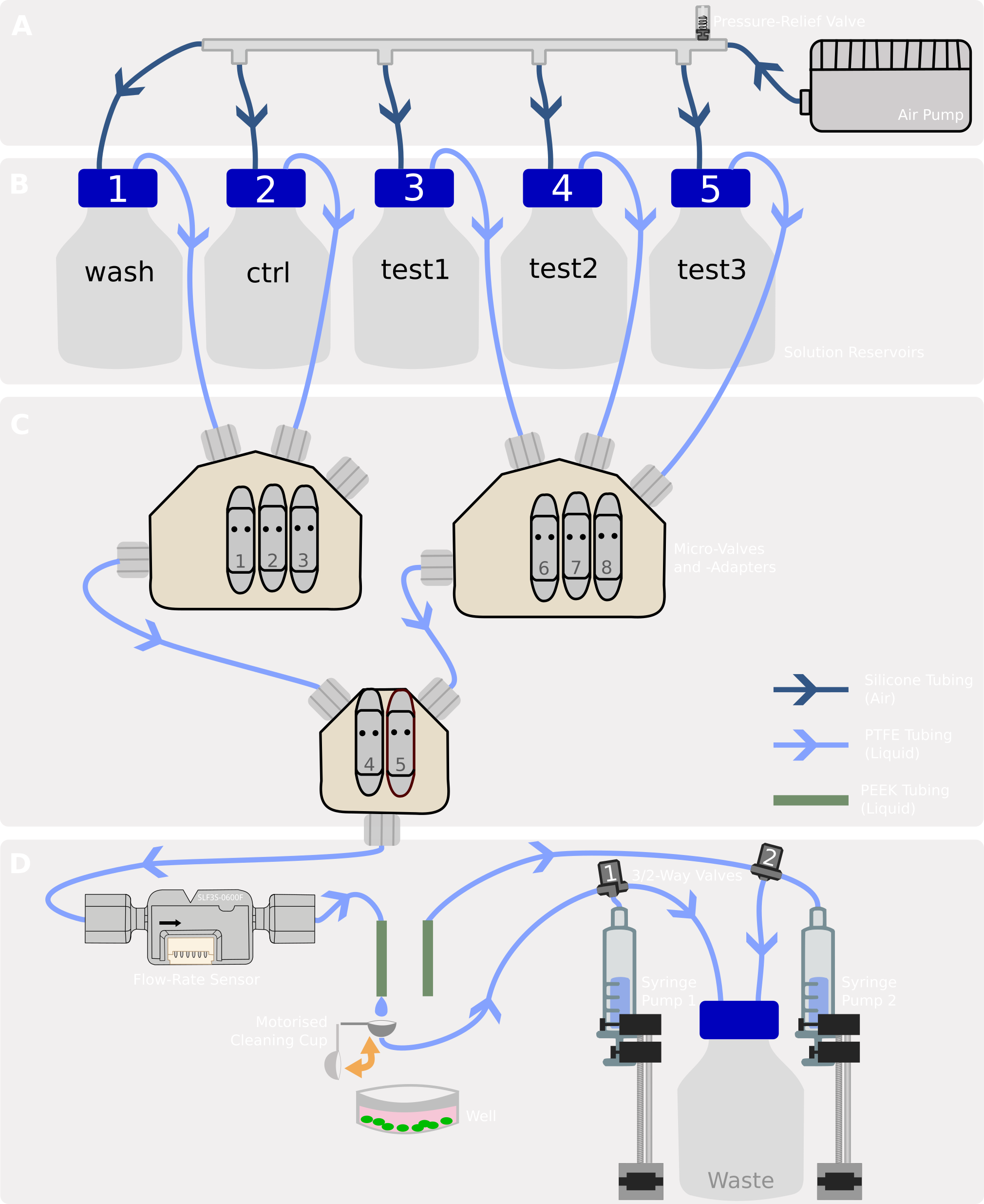
Wiring of the fluidic circuit. (A) Pressure distribution system. (B) Reservoirs with perfusion solutions. (C) Microvalve circuit and channel numbering. (D) Perfusion site with precise volume exchange.
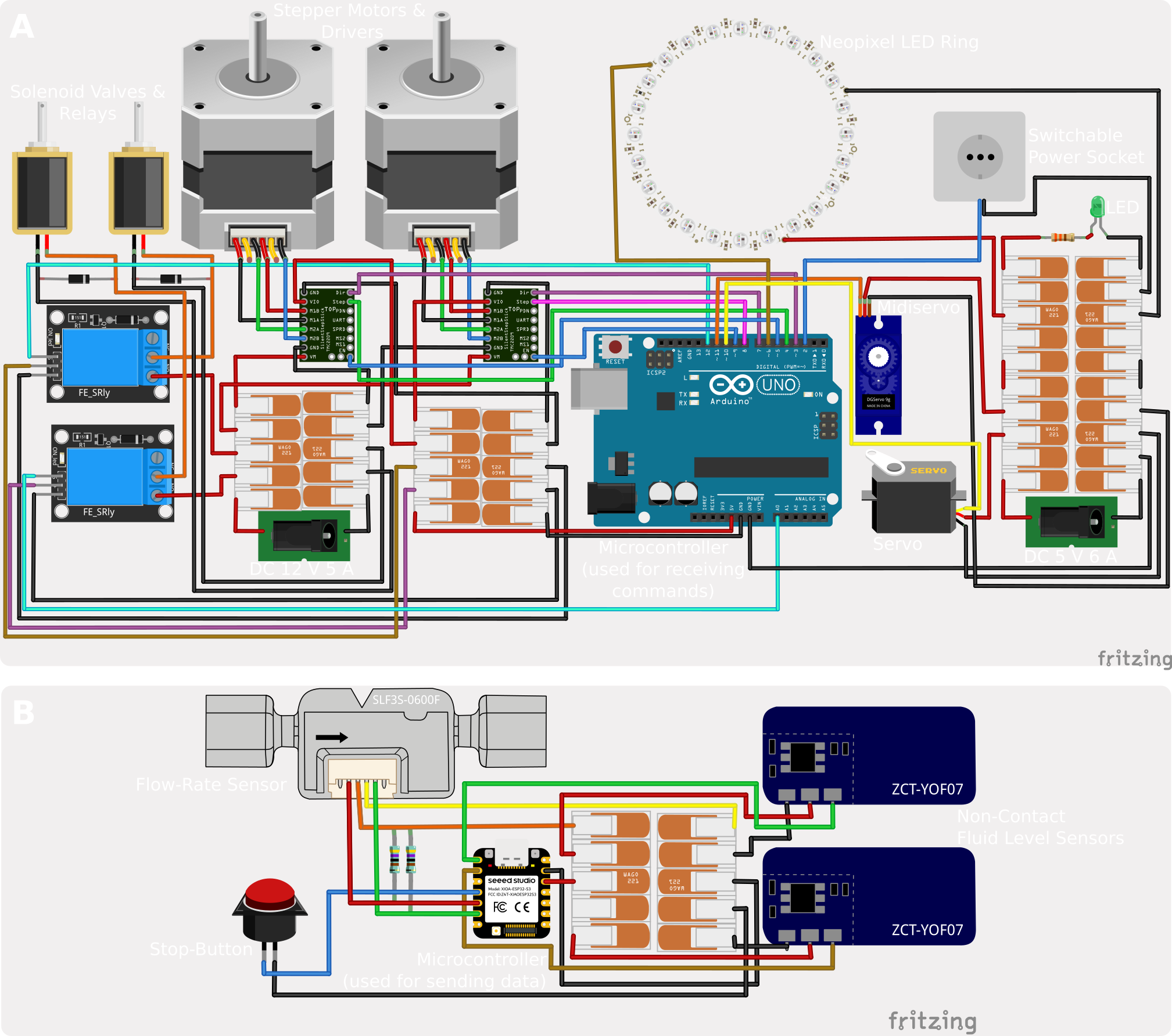
Wiring of the electrical circuits. (A) The RX system receives signals from the PC and controls the servo motors, the stepper motor drivers, relays (switchable power socket, 3/2-valve relays), and the Neopixel LED ring. (B) The TX system gathers information from the flow-rate sensor, the fluid level sensors and the stop button and sends the information to the PC.
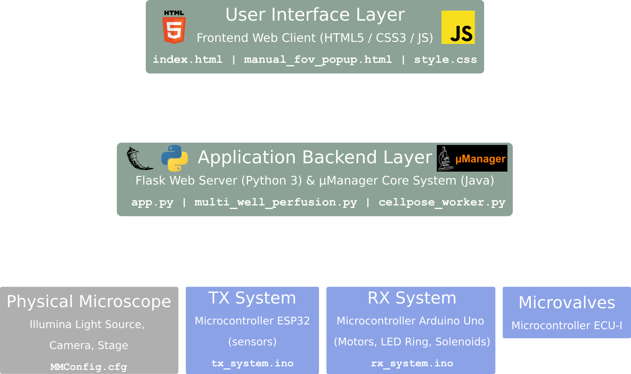
Web App Architecture. Multi-layered system showing the interaction between green software layers, blue hardware nodes, and the physical microscope components in grey.
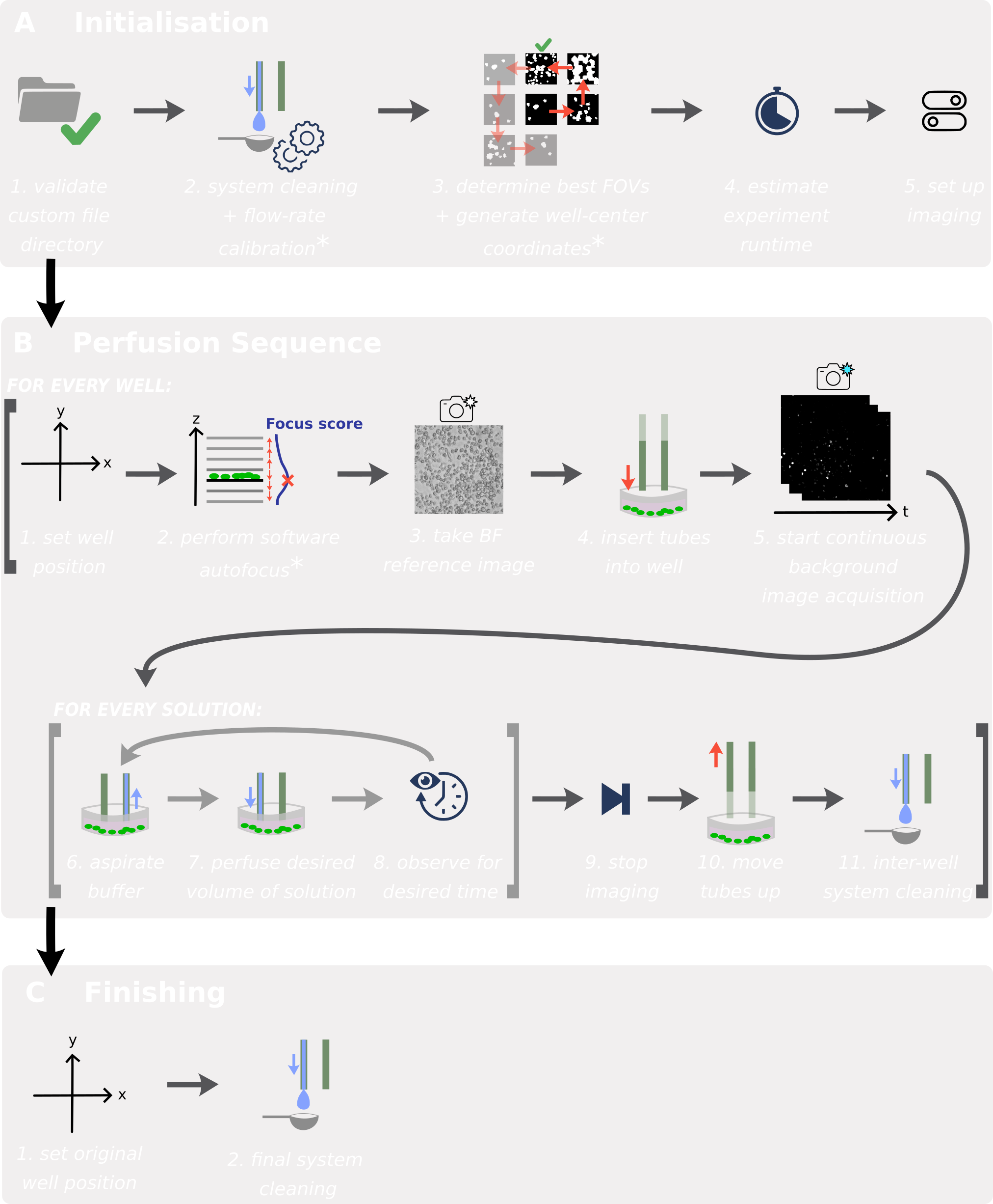
Perfusion experiment workflow sequence. (A) Initialization and sensor validation. (B) Automated well traversal, solution perfusion, and imaging loops. (C) Decontamination protocol and park execution.
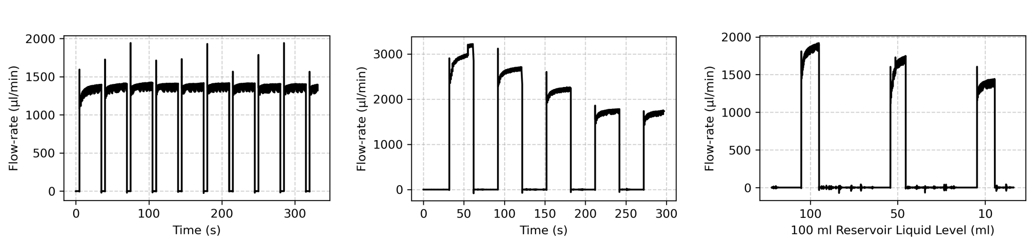
Flow-rate stability characterization. (A) Flow-rate robustness and transient oscillations observed during operational tuning. (B) Flow-rate decay resulting from increased system resistance upon integrating additional reservoirs. (C) Hydrostatic flow-rate decay as reservoir fluid levels deplete (tested across 100 mL, 50 mL, and 10 mL capacities). Modularity allows for interchangeable reservoir sizes to accommodate varying experimental volume requirements.
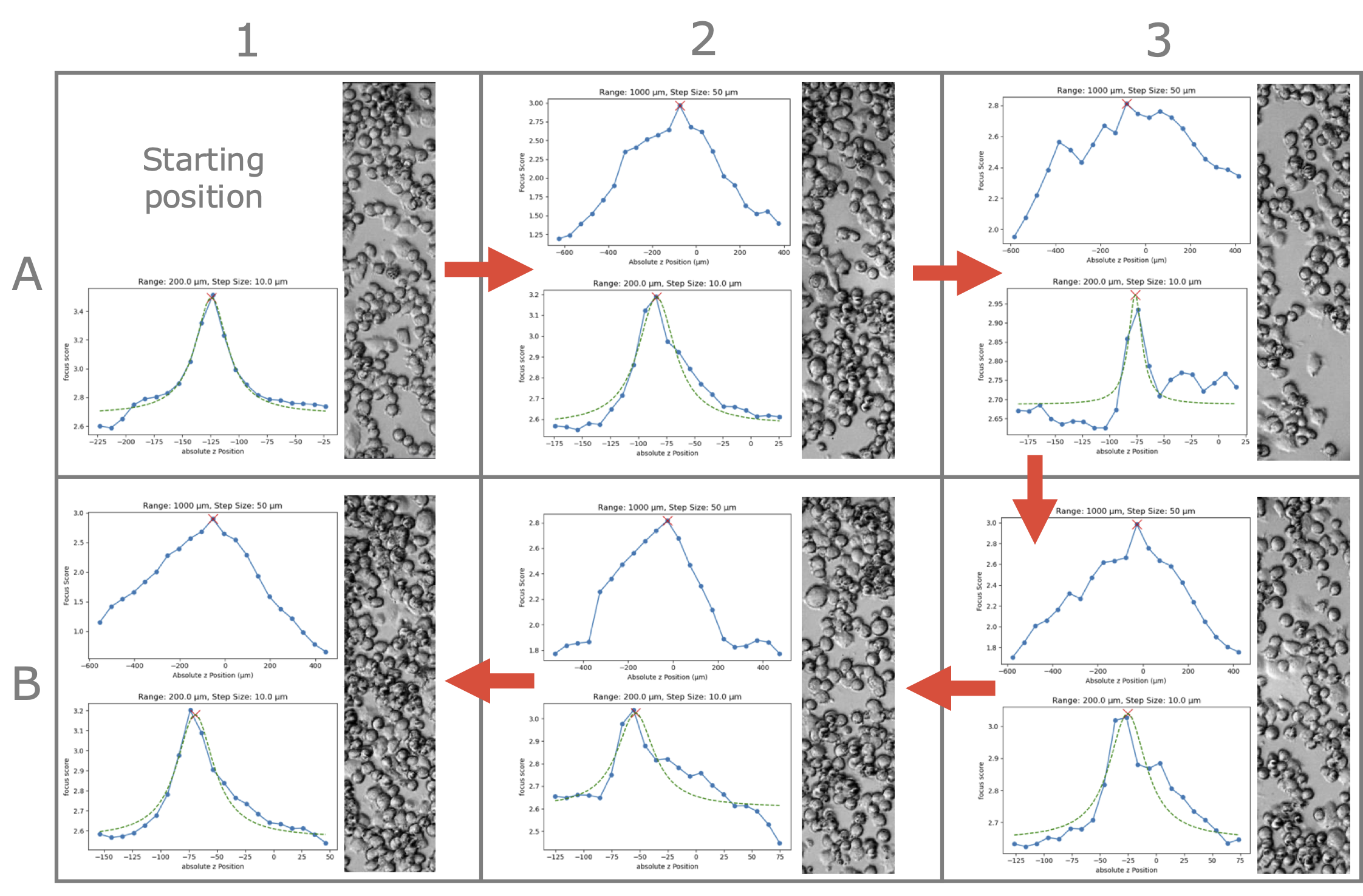
Software autofocus performance throughout a 6-well plate. For each well, except for the starting position A1, a course scan followed by a fine scan are carried out as shown on the left, resulting in a focussed sample shown on the right of each well.
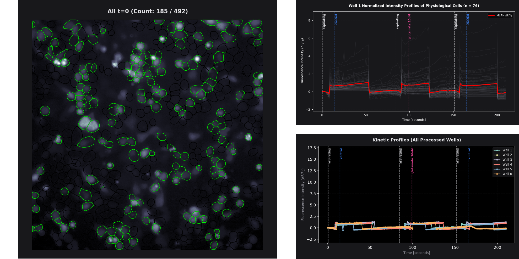
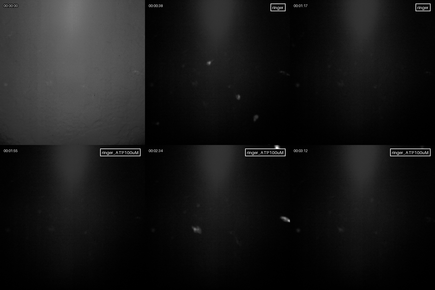
Bath perfusion experiment with GFP (left) and NEMO (right) tagged ND cells. (A) Fluorescence overlay with segmented masks detected by Cellpose. The green outlines are the cells labeled as fluorescent, the black outlines show the rest of the segmented cells. (B) Physiological fluorescence intensity change / SBR of single cells (grey) and mean (red). (C) Mean trajectories of all wells for comparison.
[1] H. Pinkard, N. Stuurman, I. E. Ivanov, et al., “Pycro-manager: Open-source software for customized and reproducible microscope control,” Nat Methods, vol. 18, 226–228, 2021. DOI: 10.1038/s41592-021-01087-6.
[2] A. D. Edelstein, M. A. Tsuchida, N. Amodaj, H. Pinkard, R. D. Vale, and N. Stuurman, “Advanced methods of microscope control using μmanager software,” Journal of Biological Methods, 2014. DOI: 10.14440/jbm.2014.36.
[3] J. Li, Z. Shang, J. H. Chen, et al., “Engineering of nemo as calcium indicators with large dynamics and high sensitivity,” Nature Methods, vol. 20, pp. 918–924, 2023. DOI: 10.1038/s41592-023-01852-9.
[4] P. Dettinger, T. Kull, G. Arekatla, et al., “Open-source personal pipetting robots with live-cell incubation and microscopy compatibility,” Nature Communications, vol. 13, no. 1, p. 2999, 2022. DOI: 10.1038/s41467- 022-30643-7.
 Version: October 2026
Click on image to play on Youtube.com
| Qty | Value | Footprint | References |
|---|---|---|---|
| 8 | Conn_01x02_Pin | Connector:memetis_01x02 | J1, J2, J3, J4, J5, J6, J7, J8 |
The 8 most common of 9 parts.


FrameworkComputer/ExpansionCards
Reference designs and documentation to create Expansion Cards for the Framework Laptop

VoronDesign/Voron-Hardware
Cool Hardware designed by the Voron Design group

hackclub/OnBoard
💡 Join 1,000 teenagers and make your first PCB with a $100 grant!


adamws/kicad-kbplacer
KiCad plugin for automatic keyboard's key placement and routing
It measures 99.5 × 89.5 mm and has 2 copper layers, 1.6 mm thick.
9 parts. The full list of its parts is on this page, with links to each part's symbol and footprint where PCBKit's library has them.
From the olxssa/perfusion_automation repository on GitHub, at the commit this page was made from: the board is FPC/custom_fpc_memetis_improved/custom_ffc.kicad_pcb and its schematic FPC/custom_fpc_memetis_improved/custom_ffc.kicad_sch. PCBKit opens the board in the browser, with nothing to install.
Its repository states no licence, so its author keeps all rights: ask olxssa before reusing the design.