

4 layers74 × 104 mm

 Oliver0804/i2cExplorer1
i2cExplorer is a powerful tool designed for exploring I2C devices on the bus using the RP2040 as the MCU within the Arduino framework.
I2cExplorer is an open-source printed circuit board by Oliver0804, from the Oliver0804/i2cExplorer repository on GitHub, published under the GPL-3.0 licence. It is a 2-layer board with 19 parts on 108 nets.
It is built around the RP2040 and S8050. Its parts include 4 connectors, 3 resistors, 3 switches, 2 ICs and 1 diode. It belongs with the RP2040 boards of this library.
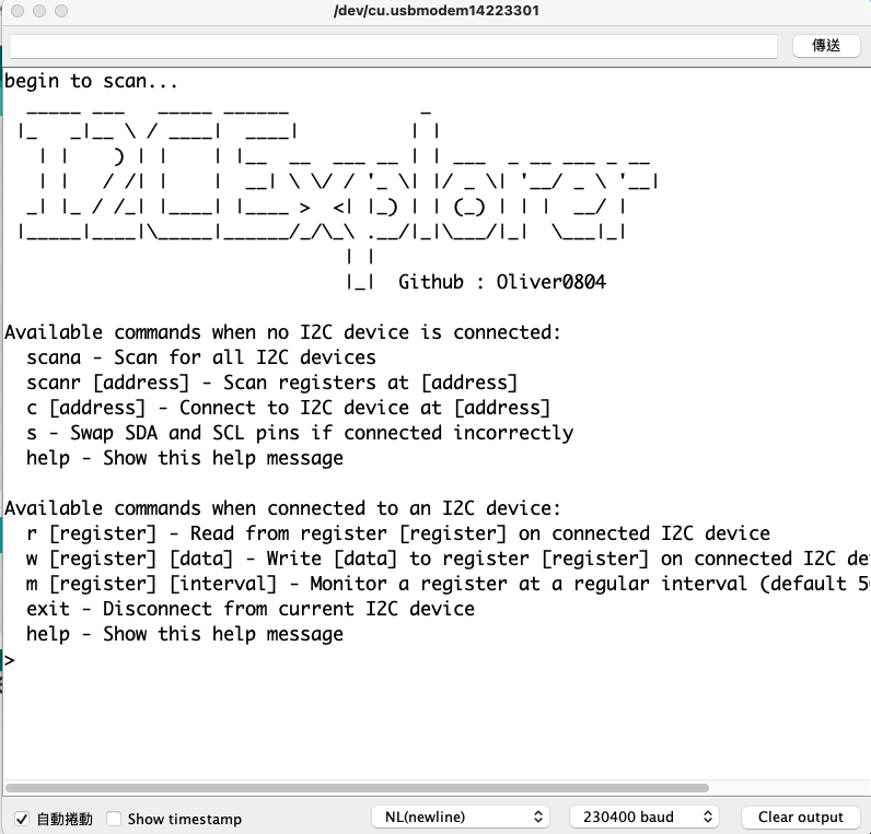
https://www.youtube.com/watch?v=PAolOif3dD0&ab_channel=BashCat
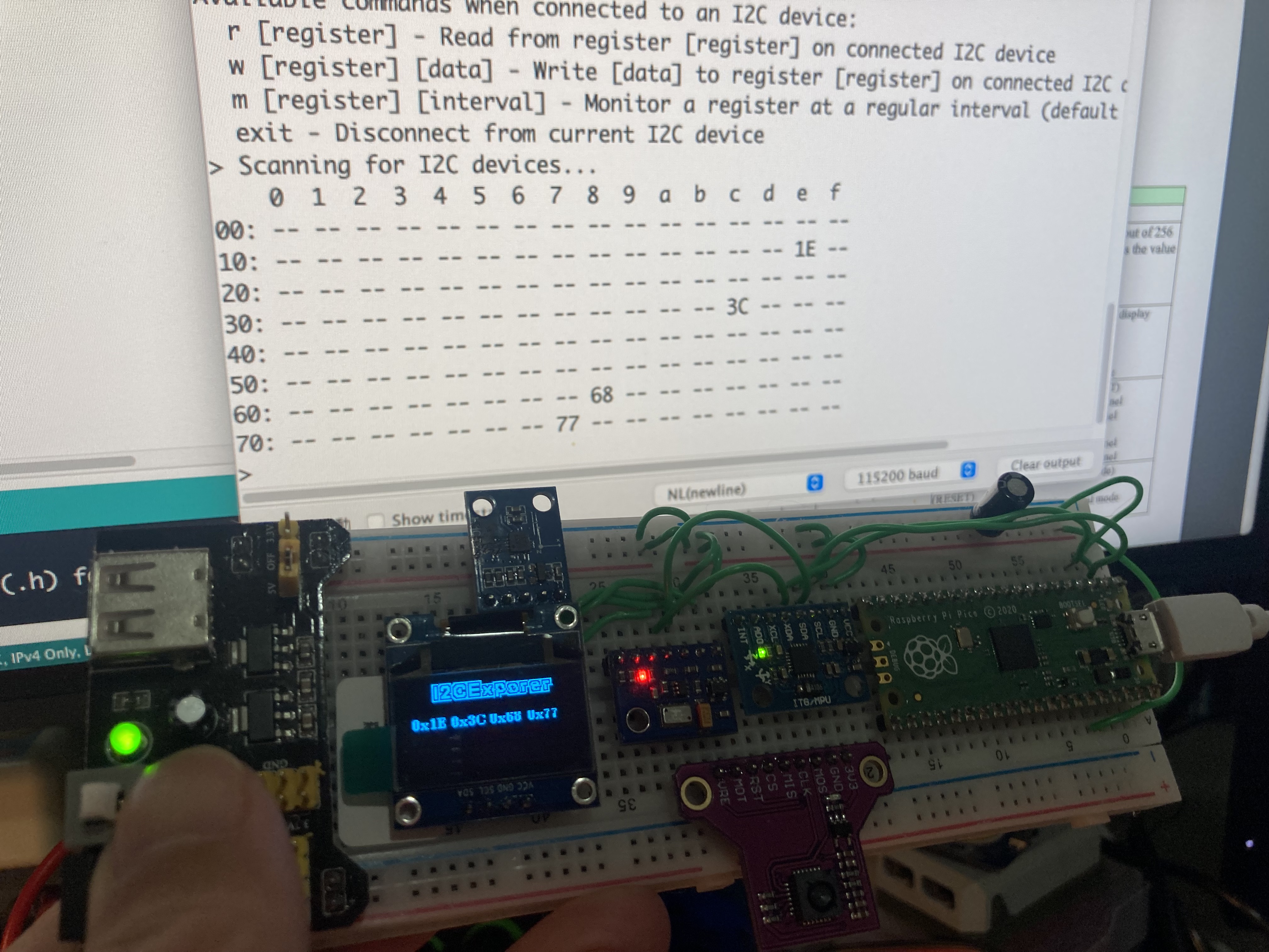
i2cExplorer is a powerful tool designed for exploring I2C devices on the bus using the RP2040 as the MCU within the Arduino framework. It allows users to interact with I2C devices via a serial interface, providing capabilities for scanning, reading, and writing I2C registers.
『I2C Explorer』是一個非常實用的工具,特別適合於解決在使用I2C通訊協議時可能遇到的一些常見問題和場景。以下是幾個典型的使用場景,以及I2C Explorer如何幫助解決這些問題:
I2C Explorer is an extremely practical tool, particularly suited for addressing common problems and scenarios encountered when using the I2C communication protocol. Below are several typical use cases, and how the I2C Explorer helps in resolving these issues:
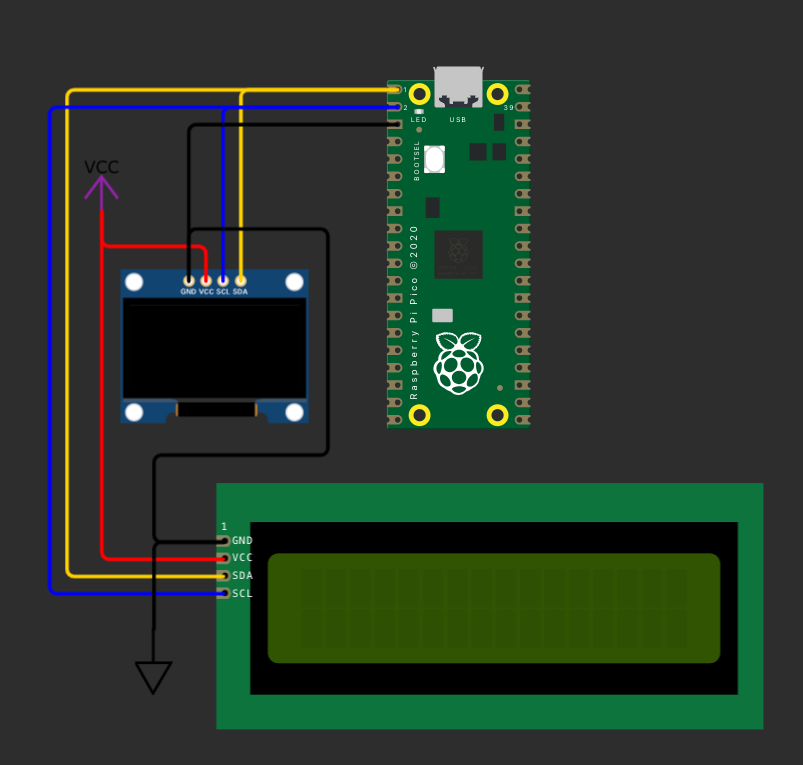
Connect any I2C device to your RP2040, using the following pins:
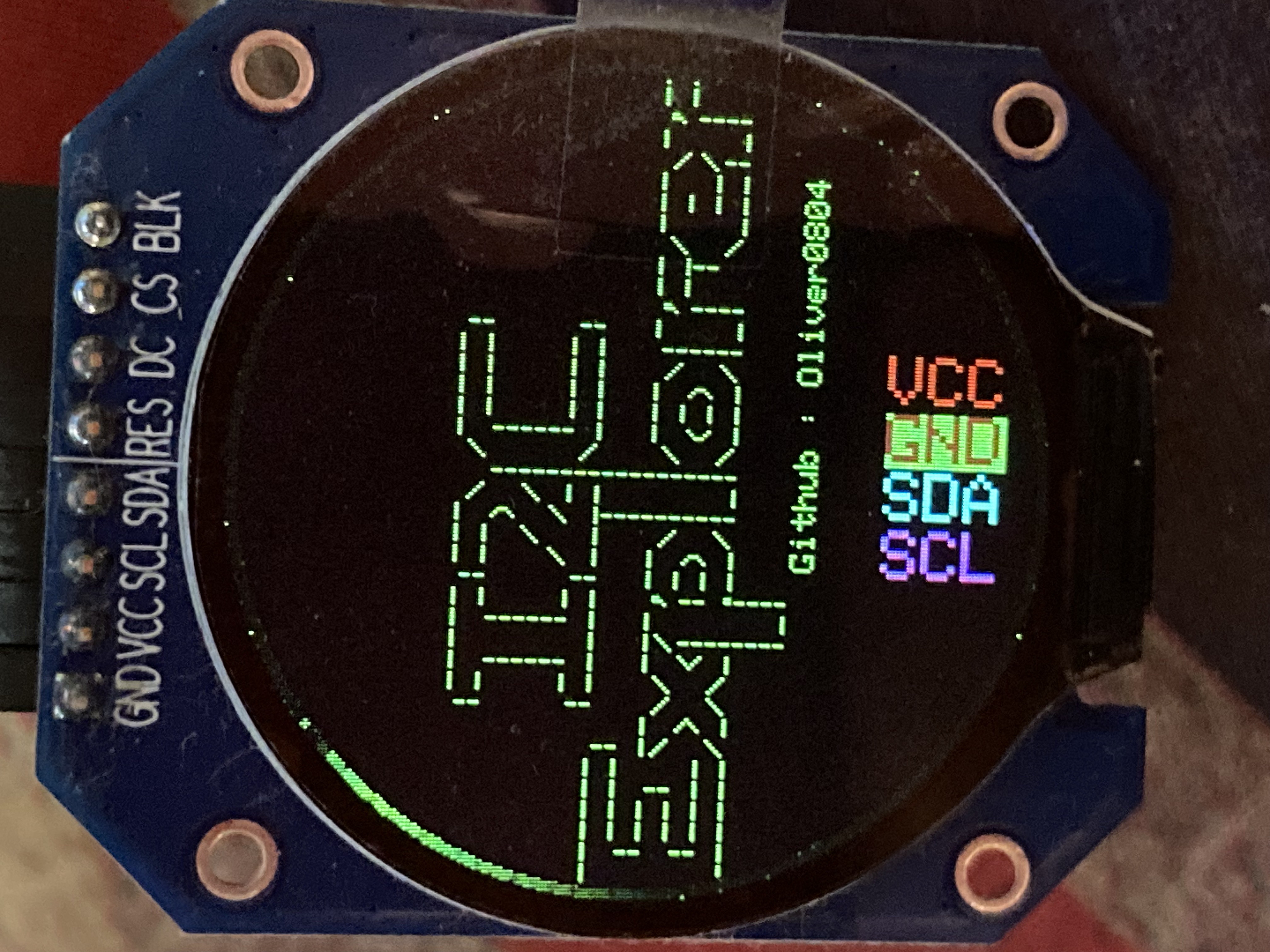
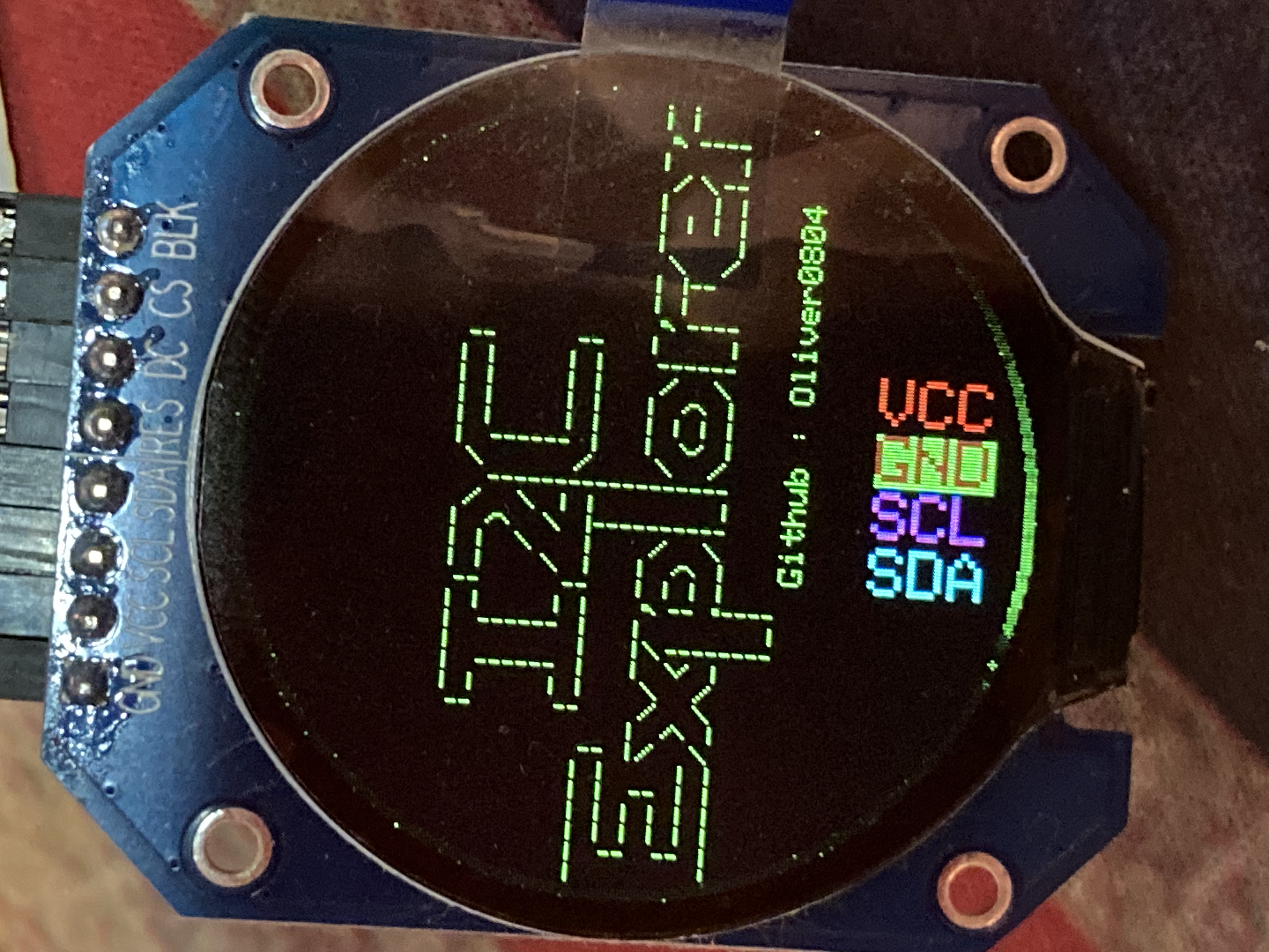
Execute the following commands through your serial terminal:
- `scana`: Scan all I2C devices on the bus.
- `scanr [address]`: Scan registers at the specified I2C address.
- `c [address]`: Connect to an I2C device at the given address.
- `r [register]`: Read from a register on the connected I2C device.
- `w [register] [data]`: Write data to a register on the connected I2C device.
- `m [register] [interval]`: Monitor a register at the specified interval (in milliseconds).
- `s` - Swap SDA and SCL pins if connected incorrectly
- `exit`: Disconnect from the current I2C device.
- `help`: Display available commands based on the connection status.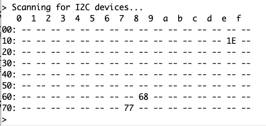
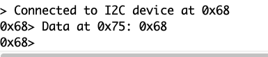
For the m command, the interval is optional (default is 500ms). The maximum allowed interval is 3000ms.
> scana
> c 0x68
> r 0x1
> w 0x1 0xFF
> m 0x1 1000
> exit
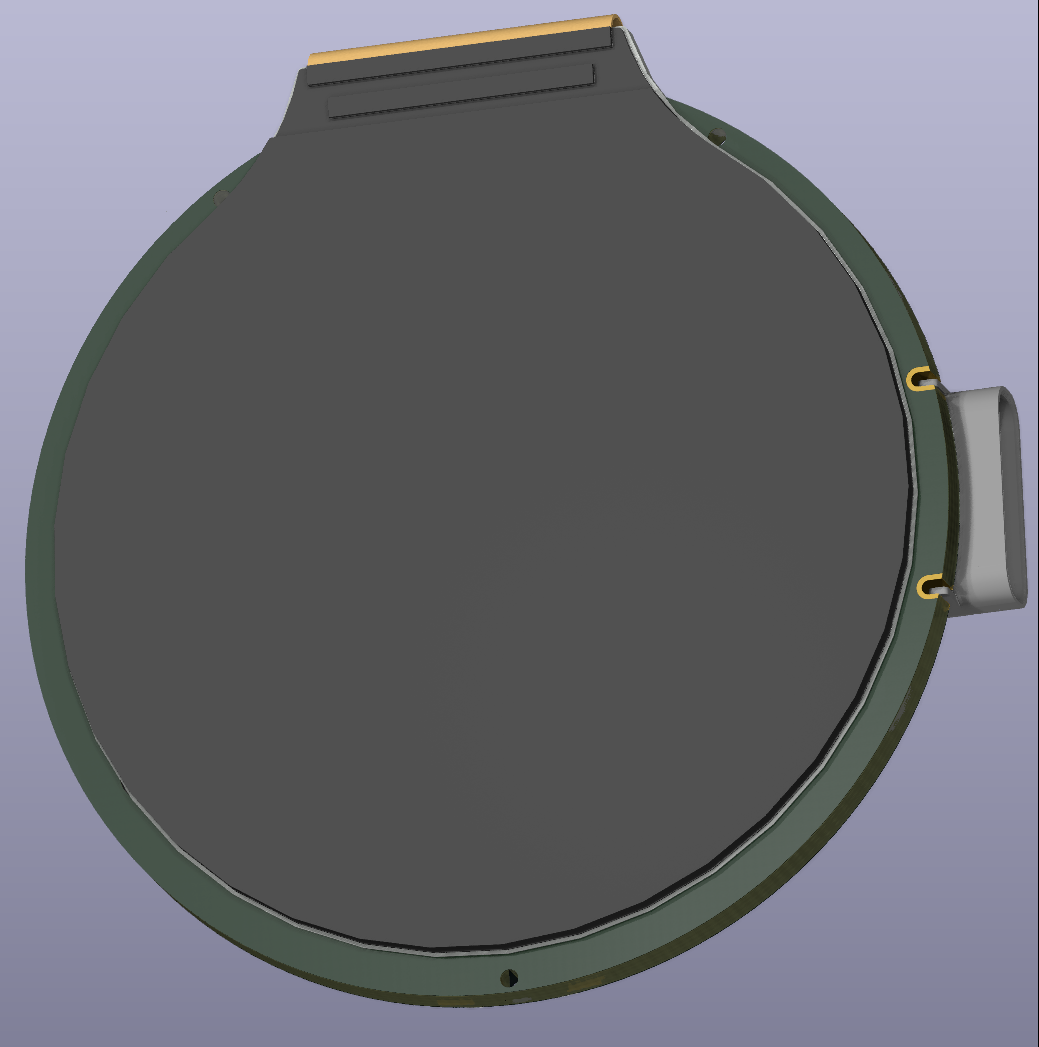
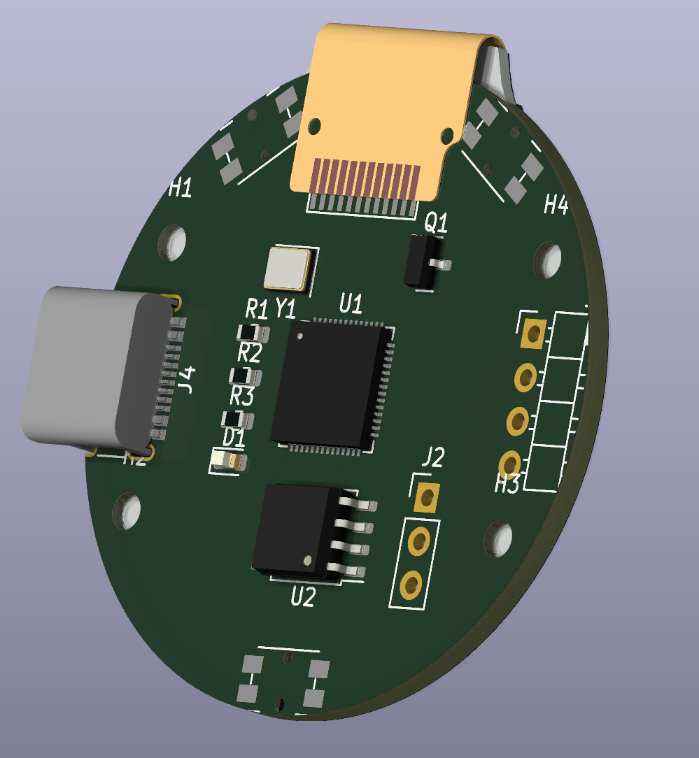
Ensure your RP2040 and I2C devices are correctly connected and configured. This tool is intended for exploration and debugging purposes.
| Qty | Value | Footprint | References |
|---|---|---|---|
| 4 | MountingHole | MountingHole:MountingHole_2.2mm_M2 | H1, H2, H3, H4 |
| 3 | R | Resistor_SMD:R_0603_1608Metric | R1, R2, R3 |
| 3 | SW_Push | Button_Switch_SMD:Panasonic_EVQPUM_EVQPUD | SW1, SW2, SW3 |
| 1 | Crystal | Crystal:Crystal_SMD_2520-4Pin_2.5x2.0mm | Y1 |
| 1 | GC9A01 | Display:GC9A01_Extended_FPC | J1 |
| 1 | I2CTest | Connector_PinHeader_2.54mm:PinHeader_1x04_P2.54mm_Horizontal | J3 |
| 1 | LED | LED_SMD:LED_0603_1608Metric | D1 |
| 1 | RP2040 | Package_DFN_QFN:QFN-56-1EP_7x7mm_P0.4mm_EP3.2x3.2mm | U1 |
| 1 | S8050 | Package_TO_SOT_SMD:SOT-23 | Q1 |
| 1 | SWDIO | Connector_PinHeader_2.54mm:PinHeader_1x03_P2.54mm_Vertical | J2 |
| 1 | USB_C_Receptacle | Connector_USB:USB_C_Receptacle_HRO_TYPE-C-31-M-12 | J4 |
| 1 | W5Q16JVSSIQ | Package_SO:SOIC-8_5.23x5.23mm_P1.27mm | U2 |
19 parts, built around the RP2040 and S8050. The full list of its parts is on this page, with links to each part's symbol and footprint where PCBKit's library has them.
From the Oliver0804/i2cExplorer repository on GitHub, at the commit this page was made from: the board is HW/i2cExplorer/i2cExplorer.kicad_pcb and its schematic HW/i2cExplorer/i2cExplorer.kicad_sch. PCBKit opens the board in the browser, with nothing to install.
Its repository publishes it under the GPL-3.0 licence: you may reuse it on that licence's terms (keep the author's notice, and for a copyleft licence share your changes alike).

CarbonComputers/Piberry-12
PiBerry v12 marks the final and most refined revision of the PiBerry handheld Linux terminal. Designed with both form and function in mind, this version brings together the best elements of previous iterations while…


tylercrumpton/magic-8-badge
An Open Source CircuitPython-compatible PCB badge that can (maybe) tell the future!

DIaLOGIKa-GmbH/modular-nerf-target
A hex-based modular system to build custom nerf gun targets

chatelao/xDuinoRail-Decoder
The friendly decoder development plattform for model railroad tinkers.

dario0603/Hotplate
Hotplate is a DIY electronics project focused on the design and development of a hotplate and its associated control electronics.
