4 layers63.6 × 86 mm
BECom
rjsc/BECom
BECom - Battery Emulator Companion - Open Source Hardware, designed to run dalathegreat/Battery-Emulator
276 parts2GPL-3.0
 Nv7-GitHub/sunshine1
The source code and PCB design for my melty brain combat robot, Sunshine!
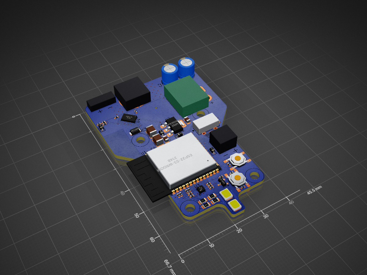
Sunshine pcb rounded is an open-source printed circuit board by Nv7-GitHub, from the Nv7-GitHub/sunshine repository on GitHub. It is a 4-layer board of 45.5 × 66.7 mm with 54 parts on 65 nets, routed with 3,417 tracks and 115 vias.
It is built around the ESP32-S3-WROOM-1-N8, LIS3MDL and SPX1117M3, with the USBLC6-2P6, H5VLD3B and 1N5819WS among its other parts. Its parts include 17 resistors, 14 capacitors, 10 diodes, 5 ICs and 4 connectors. It belongs with the ESP32 boards of this library.


This is the code for a 1lb melty-brain combat robot. This is a combat robot whose body spins and the wheel speeds are modulated while spinning for translation. There are 3 main components to this robot:
All embedded code will be implemented via platform IO. The host app code will be Tauri with React for the frontend. For replay (explained below), the brain code that is above the IO layer has to be very encapsulated so that it can be called from the Tauri rust code.
The core concept of this project is IO layers and replay. The core sensors: time (precise), wheel eRPM, ESP-NOW RSSI, magnetometer reading, battery voltage, control inputs from the driver, and accelerometer readings are all sampled at 1kHz and logged via telemetry.
All the brain code processes these inputs (which are below the IO layer) and runs code that affects the state. The state is every variable that changes over time as a result of previous inputs. This should just be the external and internal states of any filters being used.
The telemetry packets are sent out at 50 Hz, so each packet should include two state snapshots — one at the start of the packet and one at its midpoint (the 10th of its 20 samples), giving the real state at 100 Hz — and then the 20 IO layer samples that happened since the start state. The two states let the host both initialize the filters and double-check the replay against the real state twice per packet. This will minimize data usage because the host app can simply receive the state to initialize the filters and then run replay from there on. In the log files, the real state is likewise logged at 100 Hz (two snapshots per 50 Hz frame; theoretically you could even do it once but I want to be able to always have something to double-check the replay against and/or a way to handle changed code since you collected the telemetry) and the data below the IO layer is logged at the full 1kHz. Variables are NOT logged — they are a pure function of state + inputs, so the host always recomputes them (both the real and replayed versions).
The replay should use the ACTUAL robot code and just feed it a different source of IO layers instead of the raw sensors. So if you make a code change, you could re-run the code using the logged telemetry data and see if it fixes a bug that is occurring, for example.
This IO layer concept is important because it lets you implement simulation, where instead of having the receiver managing state you just implement a basic simulation of the motors and how it affects the sensors in an ideal world and then you can simulate the robot fully on the computer, once again just feeding the simulated sensor data into the IO layer.
In addition to the state and inputs (data below the IO layer) you also have the variables - data that is calculated from the state or inputs without any historical components. This is also logged at 50 Hz, but never sent over telemetry, just logged by the host app. This is once again so that if code changes occur you don't lose the data that was produced by the old code, which is necessary for determining if changes actually led to fixes.
Replay is designed with AI assistance in mind. Develop Claude skills to aid with debugging code with validation via replay and simulation in parallel to this. Design everything with debugging and ugpradeability in mind. Changing what's in the state, what the inputs are, etc. should be easy and backwards-compatible (so old log data should still be usable). Adding a new variable (especially to the state and variables, which I anticipate changing a lot) should be very easy and well documented for future AI sessions along with the codebase in general.
The robot brain has the two components mentioned before: below the IO layer, and above the IO layer. Everything above the IO layer has to be able to be run both on the host computer as well as the robot, so it should never interact with hardware directly and should be able to easily be compiled and run on a variety of host computer platforms. For below the IO layer, here is the hardware map:
IMU is an ADXL375, 11mm from the center of the robot (this is important for calculating ang vel from the centripetal accel). The IMU is rotated 45 degrees so it saturates less.
Mag is LIS3MDL
There is an LED connected to IO38 that can be PWMed. It's connected to the gate of a low side switch so you drive it high to turn on the LEDs.
IO7 is connected with a voltage divider (2kohm high, one kohm low) to the battery positive terminal
IO4 is the signal pin of the left wheel ESC (S1), IO5 is for the right wheel ESC (S2). Use bidirectional DShot 600.
USB is connected, so you can use USB for debugging info
There are 3 overall tasks running on the brain: telemetry, navigation, and control.
Telemetry should be running on the ESP32 core that is meant for telemetry. The data is getting sent out at a fixed 50 Hz and should be received from the transmitter at 500 Hz. This core should receive state (the history, or maybe it buffers the history itself but as explained earlier in each packet there's the state and then the 50 subsequent inputs). This core also uses the RSSI from the receiver and sends it over to the control core as this is one of the inputs. The receiver and transmitter should be configured to send at the absolute max strength, and the transmitter should be sending without waiting for acknowledgement or anything. For the telemetry it should be robust since any missing data will mess up replay, so determine a protocol that is able to do that without causing congestion so the packets with RSSI and control inputs can be sent at the 500 Hz. This is in a very RF noisy environment so account for that appropriately.
IMPORTANT: When the robot is disabled in the host app, it HAS to disable in real life. This is a strict requirement as it is critical to safety.
Navigation is the 1kHz sensor read and filter update loop. All the sensors can be read at 1kHz or faster (make sure to configure correctly) and all are connected via SPI so it should be fast. The filter is as follows:
Make sure to consider endian-ness correctly for telemetry or use some protocol.
The overall Kalman filter will use the magnetometer as an absolute reference (since with the DC filtered out from the butterworth it should actually represent absolute position), the accelerometer gives velocity for the kalman filter, and eventually the RSSI will either give velocity or position but that is to be determined.
The theta control defines an offset from the absolute position from the magnetometer. That way the driver can rotate the zero heading reference.
The kalman filter will need to be tuned somewhat. Develop necessary code (this will probably happen during bringup) and include instructions to tune it.
Control also happens in the same 1kHz loop. It is CRITICAL that this tight 1kHz loop does not overrun, and I should know about it when it is happening. The inputs include precise time so the host app should be receiving this, and of course loop overruns should be included in the USB output along with any initialization errors for the sensors. Make sure to have a distinct LED pattern if there are initialization errors too with the sensors, since usually I won't have USB connected during init so I would connect USB once I see that pattern (so the error should be continuously printed).
During control, the LED has to be turned on from -3 deg to +3 deg (of course relative to the driver-controlled zero heading).
The X and Y controls will be used for translational control. For the translational drift, use triangle waves in a portion of the rotation such that it can drive. The amplitude of the wave should depend on the magnitude of the X/Y control. Write a document on how to tune this (what to change and how that will affect the motion and what I should look for). I am thinking of a triangle wave instead of the usual square because the melty should be traction limited and a triangle wave should limit slip. Maybe a trapezoidal wave instead of a triangle if that would be more optimal.
There are two modes of control. There is DISABLED, which is critical to safety and the host app will control this. Then there is TANK, where the robot is driven around like a traditional robot, so throttle controls forwards backwards and the x control (side-to-side) should determine turning. Y and theta are unused. Finally, there is MELTY where throttle controls target angular speed (for now open-loop), X is for side-to-side, Y is forwards backwards, and theta controls the offset. This is holonomic unlike the previous tank drive mode so you can of course mix the X and Y. In the app design mockup (included below) there is only ENABLED and DISABLED so this needs to be changed to have DISABLED, TANK, MELTY.
There is no way that the entire codebase can be put onto the device and everything will work, so bringup needs to occur where each specific function has to be individually tested. Design a clean way of doing this. Here are the levels of bringup:
Make sure it is an easy process and write instructions.
The receiver is simply the other side of the link from the robot brain. It should receive the necessary info and send it via USB (it is an ESP32-S3 so should have plenty of bandwidth) to the host app and send data. The accompanying protocols must be developed.
The UI mockup has been made:
Fetch this design file, read its readme, and implement the relevant aspects of the design. https://api.anthropic.com/v1/design/h/ER_Esv7z8Q_IkM8_wpP-5Q?open_file=Sunshine+Dashboard.html Implement: Sunshine Dashboard.html
Note that this mockup has some unnecesary info plotted on top (e.g. CPU usage doesn't make sense, but seeing the bandwidth over the connection or the RSSI would be useful up there), and the variables are fully made up. Instead of ENABLE DISABLE there should be DISABLE, TANK, MELTY. In addition to x-y and throttle there is also the theta control. The current keybinds are: W/S for Y, A/D for X, left/right arrow for theta, and up/down arrow for throttle (where throttle adds up instead of being like when you let go it goes to zero). This should be HEAVILY low-pass filtered (even more than the current mockup) so that I can basically emulate having a controller by pulsing WASD and the left/right arrow keys.
The connections section of the UI doesn't make sense. Robot is 2S so of course adjust battery indicator colors accordingly. Get rid of the E-STOP button as that's the same as DISABLE. Inputs menu is unneeded. Retain the same graph controls but fix it because right now it's a little jerky and awkward (way too sensitive to the scroll).
You should be able to do replay, simulation, and connect to the real robot through the UI. Implement that stuff into where the "CONNECTIONS" area is currently. For replay you would pick a log file, simulation just spins up a simulation, and connecting to the robot would connect to the receiver and then look at whether the receiver is connected and all. Error handling will need to be coordinated across all devices in the chain in a robust and extendable manner.
The code needs to log a decent amount of data at 50 Hz (where each 50 Hz frame has those 20 inputs). Use binary so the file is small and of course design around the backwards compatibility aspect so that old files can be used with versions of the software that have new variables.
You should be able to plot both the actual 50 Hz data as well as your replayed data for the state variables (this applies when connected to the real robot as well as when replaying from a data file, in simulation it doesn't really make sense but they can probably just be the same thing but one is at 50 Hz). The only reason we replay even when connected to the real robot is so that we can see what's going on at 1kHz, so the replayed data should look like a high-resolution version of the 50 Hz data. Make sure to design the graphing UI such that it can handle the high density of points / quantize since of course rendering at 1kHz when you are showing a minute of data would probably cause lag issues, so consider that when implementing the graphing.
All things being plotted have their own units. You can already see this system well implemented in the mockup.
The inputs should all be plotted under the inputs dropdown. Most of the state (e.g. the kalman filter internal covariances, butterworth history) don't make sense to plot so only things like position, velocity, and the magnetometer data after the filter really make sense to plot.
Even though the control outputs are logged at 1kHz as part of the inputs, they will get re-calculated during replay and so there should be a way of viewing the new control outputs too. That's why even though during telemetry they are part of the inputs in the app graphing they should be part of the STATE since they have separate values received vs replayed. We basically have a Real State and a Replayed State which of course includes the 50 Hz things above but also the 1kHz wheel applied values.
The variables are only present in the replayed values, as they are never sent from the robot. Think of all important values. e.g. velocity calculated from the accelerometer would be a variable that should be plotted. All possibly useful info should be plottable.
The app has to call the actual C code to emulate the control and state estimation. This will require calling of C code from Rust.
Use the basic electrical model of a brushed motor. (Back-EMF source, resistance, etc.). The KV of the motors is 1100KV (this should be an easily editable constant though). I don't know the exact resistance but lets say each phase is 75mohm. The battery is a 2S 650mah 120C LiPo. Don't model battery draining but model internal resistance using like the supply current derived from the stator current in the motor, pick a reasonable internal resistance for a battery with these specs. For the magnetomer, just do ideal earth's magnetic field, same for accelerometer. here are some more physical parameters you need:
I believe the max body RPM is somewhere around 4,000, you should double check this to ensure I gave you the right-specs.
Everything should be implemented robustly. If everything is connected and setup but then I unplug and replug the receiver, the host app should handle that gracefully and make a new log file. There also should be an easy way to disable logging from the host app. If the robot momentarily loses power or disconnects and then reconnects the host app and receiver should handle this gracefully. The disabled aspect is critical to safety. The code should be very well documented (in MD files) such that future AI sessions can read an info document and know what files to edit. There should be instructions for tuning meant for humans. Also make it easy to label log files (e.g. during comp it should be based on match, but always include date and stuff)
IMPLEMENT SKILLS TO AID WITH DEBUGGING!
| Qty | Value | Footprint | References |
|---|---|---|---|
| 7 | 5.1kΩ | PCM_JLCPCB:R_0402 | R1, R2, R3, R4, R5, R6, R7 |
| 6 | 100nF | PCM_JLCPCB:C_0402 | C7, C9, C25, C26, C27, C28 |
| 5 | 1kΩ | PCM_JLCPCB:R_0402 | R11, R15, R17, R20, R21 |
| 4 | 27Ω | PCM_JLCPCB:R_0805 | R8, R10, R12, R16 |
| 4 | LED | LED_SMD:LED_PLCC_2835 | D1, D4, D5, D6 |
| 3 | H5VLD3B | PCM_JLCPCB:D_SOD-323 | D9, D10, D11 |
| 2 | 10u | Capacitor_SMD:C_1210_3225Metric | C3, C4 |
| 2 | 10uF | PCM_JLCPCB:C_0805 | C5, C6 |
| 2 | 120u | Capacitor_THT:CP_Radial_D6.3mm_P2.50mm | C1, C2 |
| 2 | 1N5819WS | PCM_JLCPCB:D_SOD-323 | D2, D3 |
| 2 | 4.7uF | PCM_JLCPCB:C_0402 | C8, C29 |
| 2 | TS-1187A-C-C-B | PCM_JLCPCB:SW-SMD_4P-L5.1-W5.1-P3.70-LS6.5-TL-2 | S1, S2 |
| 1 | 2kΩ | PCM_JLCPCB:R_0402 | R13 |
| 1 | ADXL375 | Package_LGA:LGA-14_3x5mm_P0.8mm_LayoutBorder1x6y | U4 |
| 1 | AO3400A | PCM_JLCPCB:Q_SOT-23 | Q1 |
| 1 | Conn_01x04 | custom:SolderConnector4P | J2 |
| 1 | ESP32-S3-WROOM-1 | RF_Module:ESP32-S3-WROOM-1 | U1 |
| 1 | LIS3MDL | Package_LGA:LGA-12_2x2mm_P0.5mm | U3 |
| 1 | PWRIN | Connector_AMASS:AMASS_XT30PW-M_1x02_P2.50mm_Horizontal | J1 |
| 1 | PWROUT | Connector_Wire:SolderWire-1.5sqmm_1x02_P6mm_D1.7mm_OD3mm | J3 |
| 1 | SMF5.0A | PCM_JLCPCB:D_SOD-123FL | D8 |
| 1 | SPX1117M3 | Package_TO_SOT_SMD:SOT-223-3_TabPin2 | U2 |
| 1 | SW_SPST | custom:screw_switch | SW1 |
| 1 | USBLC6-2P6 | Package_TO_SOT_SMD:SOT-666 | U8 |
| 1 | VerticalUSB | custom:CONN_GT-USB-7055A_GSW | J5 |
It measures 45.5 × 66.7 mm and has 4 copper layers, 1.6 mm thick.
54 parts, built around the ESP32-S3-WROOM-1-N8, LIS3MDL, SPX1117M3 and USBLC6-2P6. The full list of its parts is on this page, with links to each part's symbol and footprint where PCBKit's library has them.
From the Nv7-GitHub/sunshine repository on GitHub, at the commit this page was made from: the board is sunshine_pcb/sunshine_pcb-rounded.kicad_pcb and its schematic sunshine_pcb/sunshine_pcb.kicad_sch. PCBKit opens the board in the browser, with nothing to install.
Its repository states no licence, so its author keeps all rights: ask Nv7-GitHub before reusing the design.
rjsc/BECom
BECom - Battery Emulator Companion - Open Source Hardware, designed to run dalathegreat/Battery-Emulator


rjhsun/stm32f0-devboard
A minimal development board featuring an STM32F030C8T6


maximus64/opendiag-hardware
OpenDIAG - Open Source OBD2 Interface (Hardware)

luftaquila/monolith
DIY wireless real-time datalogging platform for Student Formula and Baja.

guolic1/AirDAP
基于 ESP32-S3 的无线调试器,支持 CMSIS-DAP 调试烧录和串口通信。 通过 USB 直连,或使用 Windows / Linux 主机服务将网络设备映射为 USB 调试器和串口。