



2 layers123 × 87.5 mm
FastLOGIC
Neumi/fastLOGIC
An affordable Arduino-based board designed for straightforward (industrial) logic control, ideal for building small-scale automation and control solutions.
180 parts23MIT
Development of an open, modular controller for training in emergent automation technologies
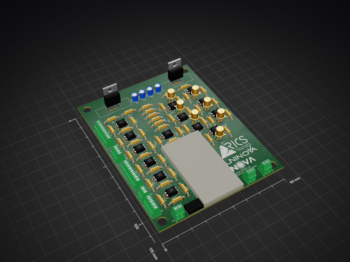
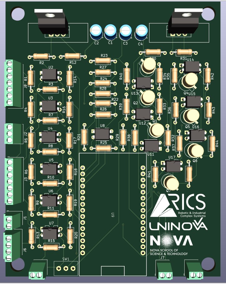
PCB kicad is an open-source printed circuit board by NOVA-RICS-Open-Lab, from the NOVA-RICS-Open-Lab/open-modular-controller repository on GitHub, published under the MIT licence. It is a 2-layer board of 90 × 115 mm with 85 parts on 72 nets, routed with 724 tracks and 14 vias.
It is built around the EL817. Its parts include 45 resistors, 17 ICs, 8 connectors, 7 transistors and 4 capacitors. It belongs with the ESP32 boards of this library.


Joao Potier1, Miguel Arvana1, Leandro Filipe1, Fabio M-Oliveira1, Andre Rocha1, Jose Barata1
1 NOVA School of Science and Technology, Center of Technology and Systems (UNINOVA-CTS), and Associated Lab of Intelligent Systems (LASI), NOVA University Lisbon, 2829-516 Lisbon, Portugal
| This work proposes the development of a controller, with modularity and flexibility as the core ideas, that allows for the integration of open-source standards like the proprietary technologies used in emergent factories and automation technologies. The implementation of this architecture led to the development of a prototype modular industrial controller that is, on average, a quarter of the cost of the new generation of industrial controllers. The developed controller was tested and validated using some educational kits. |
|
Follow these steps to create your own functional PCB and set up the ESP:
Order or Print the PCB
Gather Components
Assemble the PCB
Test the PCB
Program and Test the ESP
If all tests pass, congratulations! Your board is now ready for operation.
Once your PCB and ESP setup is complete, you can begin using the device. The ESP manages the input and output for each control pin, with a standard operating voltage of 24V. Please note:
Follow these guidelines, and your project should operate as expected!
For you to better understand this repository organization here is a quick overview of its structure and where to find what you might be looking for:
open-modular-controller
├── docs                # documentation assets
│   ├── circuits            # digital and analog circuit study
│   ├── pcb                 # pcb assets and materials
│   └── thesis.pdf          # master thesis
├── imgs                # images from this project
├── src                 # evaluation code
│   ├── libs                # developed libraries
│   └── protoboardValid.ino         # validation circuit
└── tests # use case example scriptsThe docs directory contains extensive resources, including schematics, materials lists, and PCB files, as well as the original master’s dissertation that inspired this project. Explore this folder to access all necessary assets for building, assembling, and understanding the hardware.
The presented use case for the protoboard validation showcases an asynchronous Web Server, providing a more stable connection than a synchronous web server. A toggle switch sends an HTTP request to the Processing Unit Module, initiating movement in the Kit. When the switch is active, it enables continuous operation of the Kit's process. Upon deactivation, the Industrial Kit halts movement at the start of the next cycle.
Note: The resistors R1, R4, R5, R6, R9, R13, and R21, originally specified as 1.1K, have been updated to 33K in both the schematic and materials list. This adjustment was made due to performance issues with certain conveyor belts that were not functional with the previous resistor values. Documenting this change is essential for any future debugging.
NOVA RICS Open Lab open source, and we welcome contributions from the community! See the Contribution guide for more information on the development workflow and the internals of the wandb library. For project related bugs and feature requests, visit GitHub Issues or contact novaricsopenlab@gmail.com
If you use or intend to build on top of the work in this repo, please consider citing our project:
@inproceedings{10639979,
  author={Potier, João and Arvana, Miguel and Filipe, Leandro and M-Oliveira, Fabio and Rocha, Andre Dionisio and Barata, Jose},
  booktitle={2024 IEEE 7th International Conference on Industrial Cyber-Physical Systems (ICPS)},
  title={Development of an Open, Modular Controller for Training in Emergent Automation Technologies},
  year={2024},
  doi={10.1109/ICPS59941.2024.10639979}
}This repository is released under the MIT License. Please see the LICENSE file for more details.
For any questions regarding this or any other project please contact us at novaricsopenlab@gmail.com or enroll in our Discussion Forum for sharing your ideas and sharing projects.
| Qty | Value | Footprint | References |
|---|---|---|---|
| 14 | 33k | Resistor_THT:R_Axial_DIN0207_L6.3mm_D2.5mm_P10.16mm_Horizontal | R14, R16, R17, R18, R19, R20, R29, R38, R39, R40, R42, R43, R44, R45 |
| 14 | EL817 | Package_DIP:DIP-4_W7.62mm | U2, U3, U4, U5, U6, U7, U8, U11, U12, U13, U14, U15, U16, U17 |
| 9 | 100R | Resistor_THT:R_Axial_DIN0207_L6.3mm_D2.5mm_P10.16mm_Horizontal | R12, R31, R32, R33, R34, R35, R36, R37, R41 |
| 7 | 1.1k | Resistor_THT:R_Axial_DIN0207_L6.3mm_D2.5mm_P10.16mm_Horizontal | R1, R4, R5, R6, R9, R13, R21 |
| 7 | 100k | Resistor_THT:R_Axial_DIN0207_L6.3mm_D2.5mm_P10.16mm_Horizontal | R3, R7, R8, R10, R11, R15, R25 |
| 7 | BC109 | Package_TO_SOT_THT:TO-18-3 | Q1, Q2, Q3, Q4, Q5, Q6, Q7 |
| 4 | Screw_Terminal_01x02 | TerminalBlock_Phoenix:TerminalBlock_Phoenix_MPT-0,5-2-2.54_1x02_P2.54mm_Horizontal | J1, J4, J5, J7 |
| 3 | 1k | Resistor_THT:R_Axial_DIN0207_L6.3mm_D2.5mm_P10.16mm_Horizontal | R26, R27, R28 |
| 2 | 0.1uF | Capacitor_THT:CP_Radial_D5.0mm_P2.00mm | C1, C3 |
| 2 | 1uF | Capacitor_THT:CP_Radial_D5.0mm_P2.00mm | C2, C4 |
| 2 | 6.27k | Resistor_THT:R_Axial_DIN0207_L6.3mm_D2.5mm_P10.16mm_Horizontal | R22, R24 |
| 2 | LM317_TO-220 | Package_TO_SOT_THT:TO-220-3_Vertical | U1, U10 |
| 2 | Screw_Terminal_01x07 | TerminalBlock_Phoenix:TerminalBlock_Phoenix_MPT-0,5-7-2.54_1x07_P2.54mm_Horizontal | J3, J8 |
| 1 | 164R | Resistor_THT:R_Axial_DIN0207_L6.3mm_D2.5mm_P10.16mm_Horizontal | R2 |
| 1 | 460R | Resistor_THT:R_Axial_DIN0207_L6.3mm_D2.5mm_P10.16mm_Horizontal | R30 |
| 1 | 6,27k | Resistor_THT:R_Axial_DIN0207_L6.3mm_D2.5mm_P10.16mm_Horizontal | R23 |
| 1 | LOGO | ESP32:FCTLOGO | G1 |
| 1 | LOGO | ESP32:RICS | G3 |
| 1 | LOGO | ESP32:uninova | G2 |
| 1 | Screw_Terminal_01x03 | TerminalBlock_Phoenix:TerminalBlock_Phoenix_MPT-0,5-3-2.54_1x03_P2.54mm_Horizontal | J2 |
| 1 | Screw_Terminal_01x04 | TerminalBlock_Phoenix:TerminalBlock_Phoenix_MPT-0,5-4-2.54_1x04_P2.54mm_Horizontal | J6 |
| 1 | ~ | ESP32:ESP32-JOYIT | U9 |
| 1 | ~ | ESP32:Switch | SW1 |
It measures 90 × 115 mm and has 2 copper layers, 1.6 mm thick.
85 parts, built around the EL817. The full list of its parts is on this page, with links to each part's symbol and footprint where PCBKit's library has them.
From the NOVA-RICS-Open-Lab/open-modular-controller repository on GitHub, at the commit this page was made from: the board is docs/pcb/PCB_kicad/PCB.kicad_pcb and its schematic docs/pcb/PCB_kicad/PCB.kicad_sch. PCBKit opens the board in the browser, with nothing to install.
Its repository publishes it under the MIT licence: you may reuse it on that licence's terms (keep the author's notice, and for a copyleft licence share your changes alike).
Neumi/fastLOGIC
An affordable Arduino-based board designed for straightforward (industrial) logic control, ideal for building small-scale automation and control solutions.

Millisman/EG8010
Collection of designs for the EG8010 (ASIC for single-phase SPWM control H-bridge)

fellettigiacomo/esp32-WLED-4ch-controller
Open source 4 Channel esp32-powered WLED controller with 4 relays and built in level shifter


AnaviTechnology/anavi-opto-isolator
Opto-isolator board for Arduino, ESP32, Raspberry Pi, etc. Supports 12V to 3.3V, 12V to 5V, 24V to 3.3V, 24V to 5V.