
2 layers
Encoder
byrantech/laptop
anyon_e, a highly integrated, high end, open source laptop. Attempt the impossible.
7 parts4.3kMIT
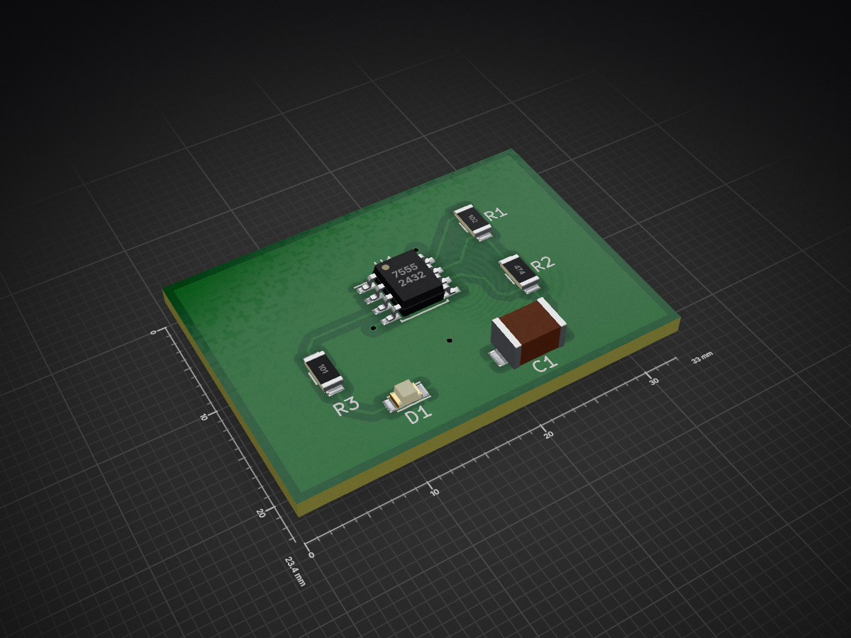
Getting to Blinky 4
Gtb is an open-source printed circuit board by notthetup, from the notthetup/GettingToBlinky4 repository on GitHub. It is a 2-layer board of 33 × 23.4 mm with 7 parts on 7 nets, routed with 29 tracks and 3 vias.
Its parts include 3 resistors, 1 capacitor, 1 IC and 1 diode.
This is a repository of (mostly) KiCad files created when following the online KiCad (and basic PCB design) tutorial by Chris Gammel. You can follow along the tutorial on this YouTube playlist
This design has a couple of changes compared to Chris's design. At the end of the tutorial series Chris realises that the resistance on his LED was too high, making the LED very dim. So I changed the value of R3 from 1KΩ to 100Ω.
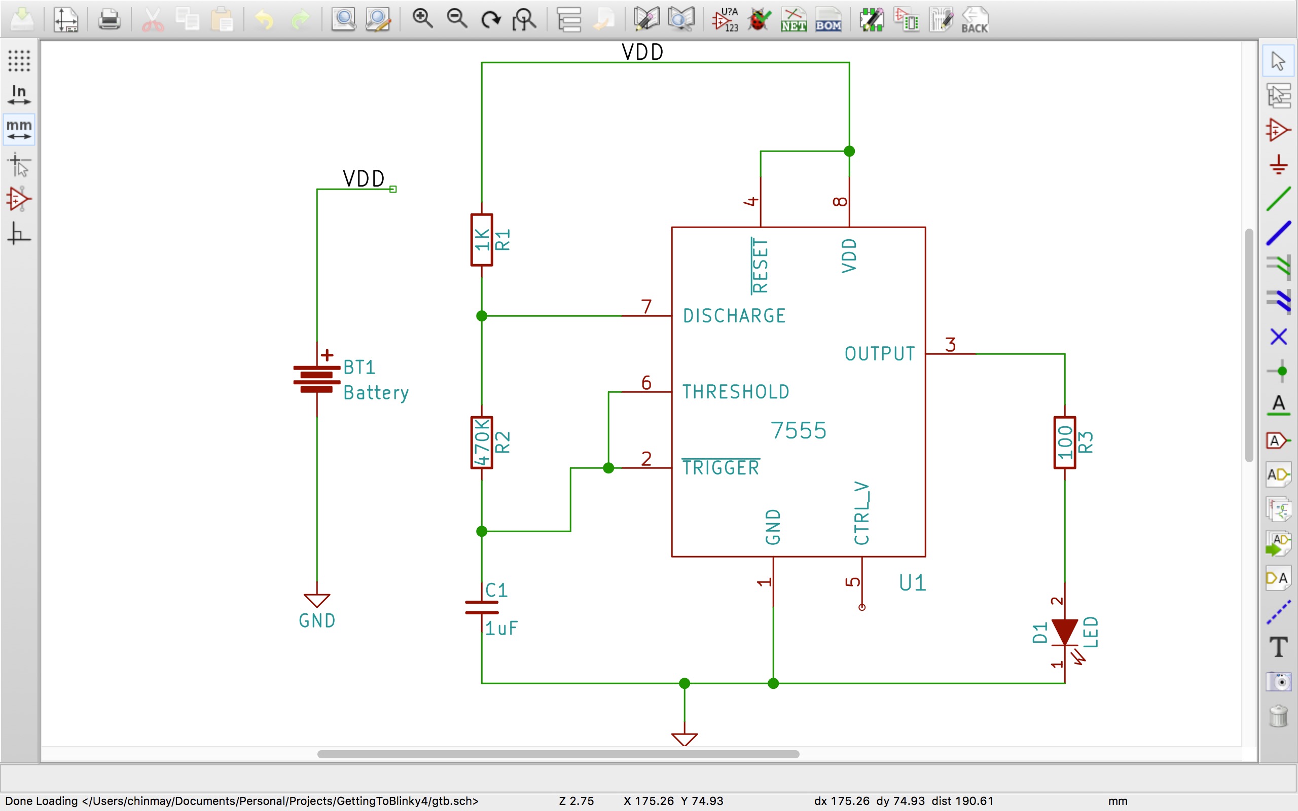
I was unable to find 470kΩ 0805 resistors for R2 so I switched to the nearest value I found which was 510kΩ (this should only affect the frequency of blinking)
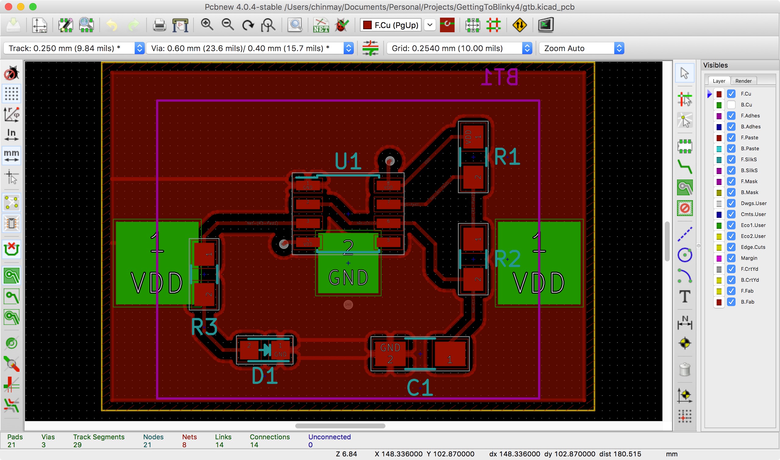
Since I was using OSHPark for PCB Fabrication, which charges per sq-inch, I tried to reduce the area of the PCB by making the layout of the battery holder as small as I could.
A major issue when soldering was the orientation of various componets. Two components are sensitive to orientation and need to be oriented correctly for the circuit to work.
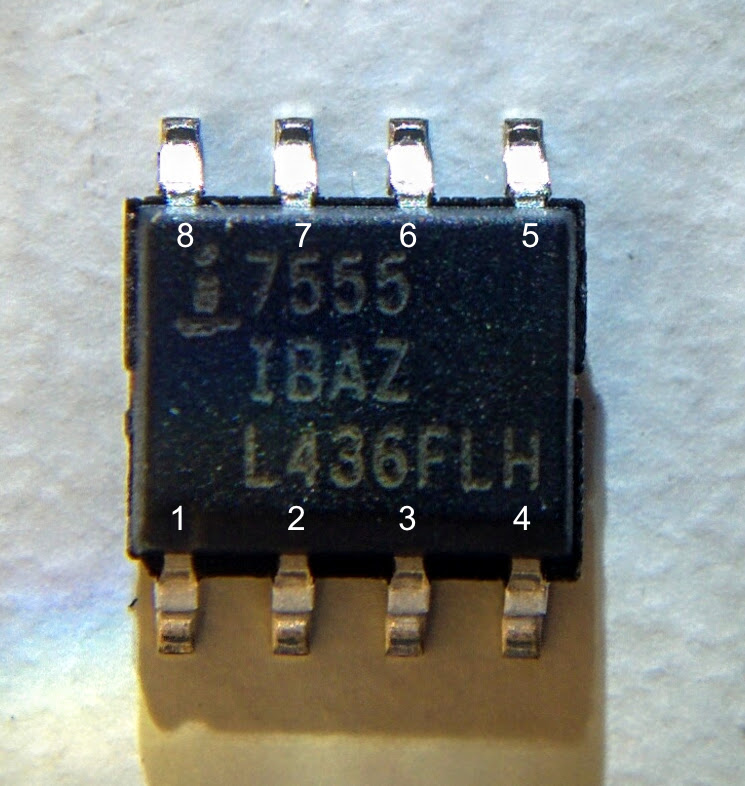
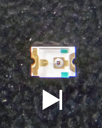
One minor issue was that I accidently sourced for a 0805 capacitor package instead of a 1206. That's also not really a problem as it is possible to solder a 0805 capacitor onto a 1206 footprint.
| Qty | Value | Footprint | References |
|---|---|---|---|
| 1 | 100 | Resistors_SMD:R_0805_HandSoldering | R3 |
| 1 | 1K | Resistors_SMD:R_0805_HandSoldering | R1 |
| 1 | 1uF | Capacitors_SMD:C_1206_HandSoldering | C1 |
| 1 | 470K | Resistors_SMD:R_0805_HandSoldering | R2 |
| 1 | 7555 | Housings_SOIC:SOIC-8_3.9x4.9mm_Pitch1.27mm | U1 |
| 1 | Battery | gtb:S8211R | BT1 |
| 1 | LED | LEDs:LED_0805 | D1 |
byrantech/laptop
anyon_e, a highly integrated, high end, open source laptop. Attempt the impossible.


AxxAxx/AxxSolder
STM32 Based soldering station for JBC cartridges, 9-24 VDC and USB-PD power


jamro/tiny-engineer
A small desktop robot that brings an AI coding assistant to life, physically acting out when it reads files, thinks, writes code, and finishes work.

hoglet67/RGBtoHDMI
Bare-metal Raspberry Pi project that provides pixel-perfect sampling of Retro Computer RGB/YUV video and conversion to HDMI

It measures 33 × 23.4 mm and has 2 copper layers, 1.6 mm thick.
7 parts. The full list of its parts is on this page, with links to each part's symbol and footprint where PCBKit's library has them.
From the notthetup/GettingToBlinky4 repository on GitHub, at the commit this page was made from: the board is gtb.kicad_pcb. PCBKit opens the board in the browser, with nothing to install.
Its repository states no licence, so its author keeps all rights: ask notthetup before reusing the design.