4 layers99.1 × 88.9 mm
 notJoon/core-memory
ferrite core memory PBC & firmware
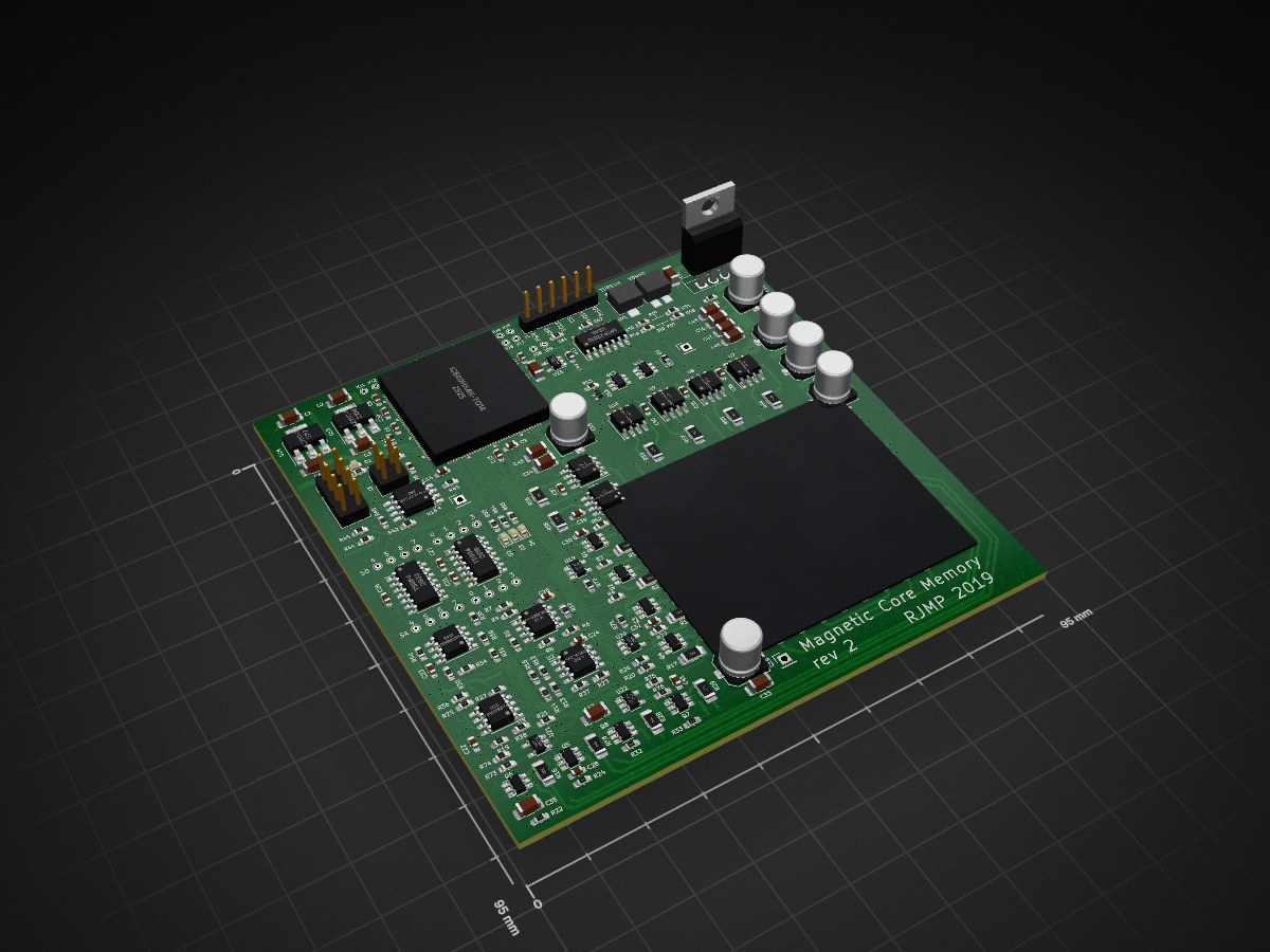
CoreMem is an open-source printed circuit board by notJoon, from the notJoon/core-memory repository on GitHub. It is a 2-layer board of 95 × 95 mm with 196 parts on 225 nets, routed with 2,275 tracks and 326 vias.
It is built around the ICE40HX4K-TQ144, W25Q32JVSSIQ TR and MCP42010-I/P, with the CDBU0520 and DMG1012T-7 among its other parts. Its parts include 74 resistors, 49 capacitors, 23 ICs, 11 transistors and 5 diodes. It belongs with the FPGA and CPLD boards of this library.


ferrite core memory PCB & firmware
Pre-generated Gerber files are in the gerber/ directory and can be submitted to a PCB fabricator directly.
| File | Layer |
|---|---|
CoreMem-F_Cu.gbr | Front copper |
CoreMem-B_Cu.gbr | Back copper |
CoreMem-F_Mask.gbr | Front solder mask |
CoreMem-B_Mask.gbr | Back solder mask |
CoreMem-F_SilkS.gbr | Front silkscreen |
CoreMem-B_SilkS.gbr | Back silkscreen |
CoreMem-Edge_Cuts.gbr | Board outline |
CoreMem-PTH.drl | Plated drill holes |
CoreMem-NPTH.drl | Non-plated drill holes |
Zip the contents of gerber/ and upload the archive to your fabricator (JLCPCB, PCBWay, OSH Park, etc.).
If you modify CoreMem.kicad_pcb, regenerate the files with KiCad 5 or later.
Prerequisites: KiCad 5.x or later
CoreMem.kicad_pcb in KiCad PCB Editor (Pcbnew).gerber/.F.Cu, B.Cu, F.SilkS, B.SilkS, F.Mask, B.Mask, Edge.Cuts.gerber/ directory and submit to your fabricator.| Qty | Value | Footprint | References |
|---|---|---|---|
| 28 | 0.1uF | Capacitor_SMD:C_0603_1608Metric_Pad1.05x0.95mm_HandSolder | C10, C11, C12, C13, C14, C20, C21, C22, C23, C24, C25, C26, C27, C28, C29, C30 +12 |
| 24 | 22k | Resistor_SMD:R_0603_1608Metric_Pad1.05x0.95mm_HandSolder | R10, R13, R14, R15, R22, R23, R24, R25, R26, R27, R32, R33, R34, R35, R36, R37 +8 |
| 15 | 10k | Resistor_SMD:R_0603_1608Metric_Pad1.05x0.95mm_HandSolder | R42, R43, R44, R45, R47, R52, R53, R60, R70, R71, R72, R73, R74, R75, R76 |
| 15 | 10uF | Capacitor_SMD:C_1206_3216Metric_Pad1.42x1.75mm_HandSolder | C1, C2, C3, C4, C5, C32, C33, C34, C35, C42, C43, C45, C46, C47, C48 |
| 14 | 10 | Resistor_SMD:R_1206_3216Metric_Pad1.42x1.75mm_HandSolder | R1, R2, R11, R16, R17, R18, R28, R29, R54, R55, R56, R57, R58, R59 |
| 10 | DMG6602SVTQ-7 | Package_TO_SOT_SMD:TSOT-23-6 | Q1, Q2, Q3, Q4, Q5, Q6, Q7, Q8, Q13, Q14 |
| 9 | TestPoint | TestPoint:TestPoint_THTPad_D1.0mm_Drill0.5mm | IO1, IO2, IO3, IO4, IO5, IO6, IO7, IO8, IO9 |
| 8 | 1k | Resistor_SMD:R_0603_1608Metric_Pad1.05x0.95mm_HandSolder | R3, R4, R12, R19, R20, R21, R30, R31 |
| 6 | 100uF | Capacitor_SMD:C_Elec_6.3x7.7 | C15, C16, C17, C18, C19, C44 |
| 6 | DMHC3025LSD-13 | Package_SO:SOIC-8_3.9x4.9mm_P1.27mm | U7, U8, U9, U10, U11, U12 |
| 4 | 100 | Resistor_SMD:R_0603_1608Metric_Pad1.05x0.95mm_HandSolder | R41, R61, R77, R78 |
| 4 | 261 | Resistor_SMD:R_0603_1608Metric_Pad1.05x0.95mm_HandSolder | R62, R63, R64, R65 |
| 4 | LED | LED_SMD:LED_0603_1608Metric | D1, D2, D3, D4 |
| 4 | OPA2365AIDR | Package_SO:SOIC-8_3.9x4.9mm_P1.27mm | U1, U2, U3, U4 |
| 4 | QS5K2 | Package_TO_SOT_SMD:TSOT-23-5 | U19, U20, U21, U22 |
| 3 | GND | Connector_PinHeader_2.54mm:PinHeader_1x01_P2.54mm_Vertical | TP17, TP18, TP19 |
| 2 | 0 | Resistor_SMD:R_0603_1608Metric_Pad1.05x0.95mm_HandSolder | R48, R49 |
| 2 | 0/DNP | Resistor_SMD:R_0603_1608Metric_Pad1.05x0.95mm_HandSolder | R50, R51 |
| 2 | 10k | CoreMem:ST4EB | RV1, RV2 |
| 2 | TS864 | Package_SO:SOIC-14_3.9x8.7mm_P1.27mm | U5, U6 |
| 1 | 100k | Resistor_SMD:R_0603_1608Metric_Pad1.05x0.95mm_HandSolder | R46 |
| 1 | AZ1117-1.2 | Package_TO_SOT_SMD:SOT-223-3_TabPin2 | U13 |
| 1 | AZ1117-3.3 | Package_TO_SOT_SMD:SOT-223-3_TabPin2 | U14 |
| 1 | CDBU0520 | Diode_SMD:D_0603_1608Metric | D5 |
| 1 | CTRL | Connector_PinHeader_2.54mm:PinHeader_1x06_P2.54mm_Vertical | J1 |
| 1 | Conn_02x02_Odd_Even | Connector_PinHeader_2.54mm:PinHeader_2x02_P2.54mm_Vertical | J3 |
| 1 | CoreArray | CoreMem:CoreArray | F1 |
| 1 | DMG1012T-7 | digikey-footprints:SOT-523 | Q12 |
| 1 | ICE40HX4K-TQ144 | CoreMem:ICE40HX4K-TQ144 | U15 |
| 1 | LM338 | Package_TO_SOT_THT:TO-220-3_Vertical | U18 |
| 1 | MCP42010 | Package_SO:SOIC-14_3.9x8.7mm_P1.27mm | U17 |
| 1 | PROG | Connector_PinHeader_2.54mm:PinHeader_2x04_P2.54mm_Vertical | J2 |
| 1 | SA0 | TestPoint:TestPoint_THTPad_D1.0mm_Drill0.5mm | TP1 |
| 1 | SA1 | TestPoint:TestPoint_THTPad_D1.0mm_Drill0.5mm | TP2 |
| 1 | SA2 | TestPoint:TestPoint_THTPad_D1.0mm_Drill0.5mm | TP3 |
| 1 | SA3 | TestPoint:TestPoint_THTPad_D1.0mm_Drill0.5mm | TP6 |
| 1 | SA4 | TestPoint:TestPoint_THTPad_D1.0mm_Drill0.5mm | TP4 |
| 1 | SA5 | TestPoint:TestPoint_THTPad_D1.0mm_Drill0.5mm | TP5 |
| 1 | SA6 | TestPoint:TestPoint_THTPad_D1.0mm_Drill0.5mm | TP7 |
| 1 | SA7 | TestPoint:TestPoint_THTPad_D1.0mm_Drill0.5mm | TP8 |
| 1 | SD0 | TestPoint:TestPoint_THTPad_D1.0mm_Drill0.5mm | TP9 |
| 1 | SD1 | TestPoint:TestPoint_THTPad_D1.0mm_Drill0.5mm | TP10 |
| 1 | SD2 | TestPoint:TestPoint_THTPad_D1.0mm_Drill0.5mm | TP11 |
| 1 | SD3 | TestPoint:TestPoint_THTPad_D1.0mm_Drill0.5mm | TP14 |
| 1 | SD4 | TestPoint:TestPoint_THTPad_D1.0mm_Drill0.5mm | TP13 |
| 1 | SD5 | TestPoint:TestPoint_THTPad_D1.0mm_Drill0.5mm | TP12 |
| 1 | SD6 | TestPoint:TestPoint_THTPad_D1.0mm_Drill0.5mm | TP15 |
| 1 | SD7 | TestPoint:TestPoint_THTPad_D1.0mm_Drill0.5mm | TP16 |
| 1 | SiT2001B | Package_TO_SOT_SMD:TSOT-23-5 | U23 |
| 1 | W25Q32JVSSIQ_TR | digikey-footprints:SOIC-8_W5.6mm | U16 |
It measures 95 × 95 mm and has 2 copper layers, 1.6 mm thick.
196 parts, built around the ICE40HX4K-TQ144, W25Q32JVSSIQ TR, MCP42010-I/P and CDBU0520. The full list of its parts is on this page, with links to each part's symbol and footprint where PCBKit's library has them.
From the notJoon/core-memory repository on GitHub, at the commit this page was made from: the board is CoreMem.kicad_pcb. PCBKit opens the board in the browser, with nothing to install.
Its repository states no licence, so its author keeps all rights: ask notJoon before reusing the design.

embelon/hyperram_cyclonev_pcb
Simple PCB to connect HyperRAM memories to Cyclone V SoC Development Kit via HSMC connector


embelon/hyperram_asic_pcb
Test PCB for CARAVEL ASIC with HyperRAM memory (S27KL0641)

embelon/hyperram_asic_qfn_pcb
Test PCB for CARAVEL ASIC in QFP package with HyperRAM memory (S27KL0641)


Vishalbabu-09/Auralab_Workstation
Advanced 4-layer PCB design featuring split-plane noise isolation (AGND/DGND) and asynchronous dual-core processing. Implements a handheld multi-tool oscilloscope, current tracker, and symmetrical DC power supply.
