2 layers66.9 × 74.5 mm

 notgate/sph0645f_asr
Dual-SPH0645 Raspberry Pi prototype with audio capture, FFT signal processing, PCB design, and offline LLM inference.
RPI4B Dual SPH0645 RevA is an open-source printed circuit board by notgate, from the notgate/sph0645f_asr repository on GitHub. It is a 2-layer board of 70 × 50 mm with 20 parts on 9 nets, routed with 50 tracks and 5 vias.
Its parts include 3 resistors, 3 connectors, 2 ICs and 1 capacitor. It belongs with the audio and music boards of this library.
Raspberry Pi 4 project: microphone input, local transcription tests, and keyboard-style output.

Original point of the project was to design a headset which can have more clarity on microphone input and restructure the output using a local speech recognition LLM called faster whisper.
The proof of concept combines embedded Linux, I²S audio hardware, local speech recognition, and Bluetooth HID keyboard output. Two MEMS microphones provide digital audio input and a way to compare microphone signals for cleaner offline transcription.
I would have chosen Optical MEMS over MEMS because its more precise using lasers over capacitate but only company which I looked into has it behind closed doors and not consumer available.
The hardware-facing audio path is written in Rust rather than Python. It keeps capture and signal handling in compiled code while still producing standard WAV files for the recognizer.
cd backend
cargo test
cargo run -- prepare input.wav ready.wav
cargo run -- capture captured.wav 3000
The automated tests use generated WAV data. The default-device capture path is implemented, but Raspberry Pi ALSA operation and capture latency have not been measured in this repository.
The Model 1 KiCad carrier brings the two microphone breakouts, Raspberry Pi harness, channel-select jumpers, clock-damping positions, and signal test points into one editable design. Both microphones share the I²S clock and data lines while opposite SELECT states place them in separate left and right slots.
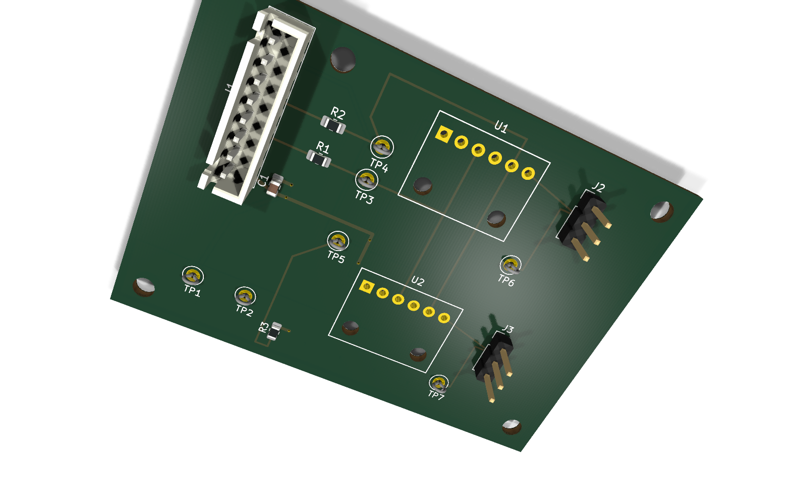 | 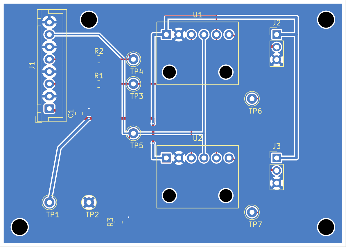 |
| 3d view | Two-layer PCB routing |
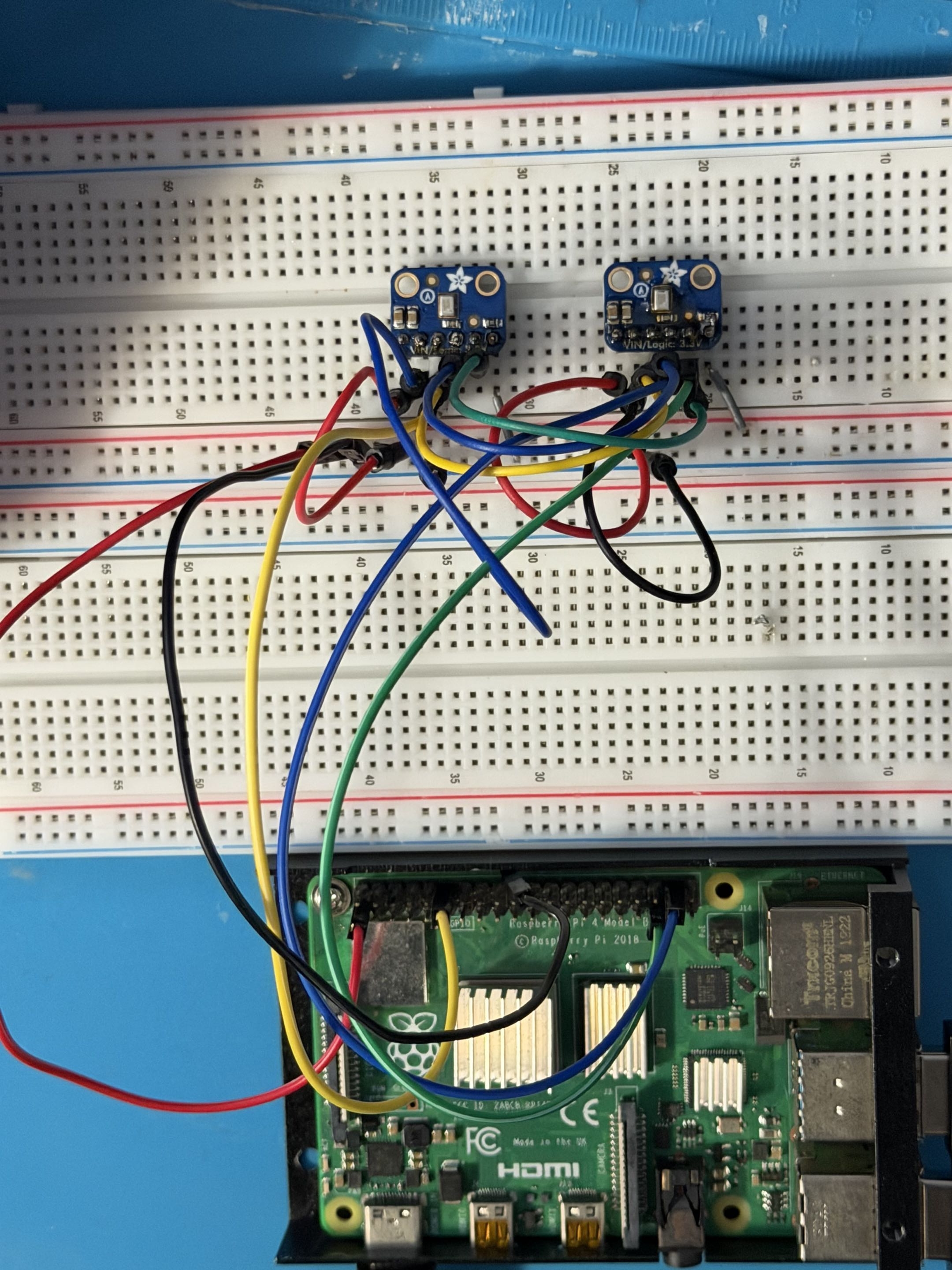 | 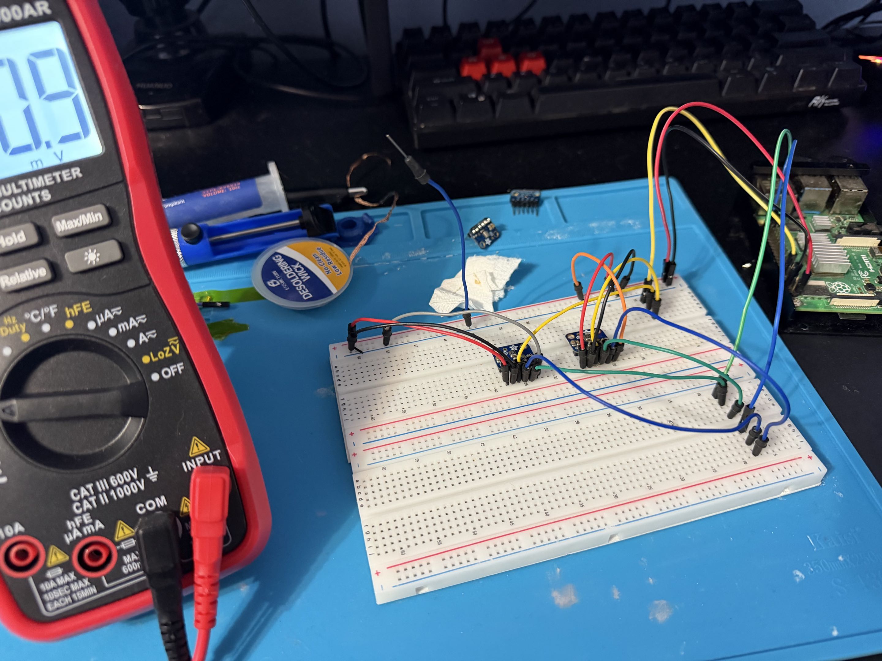 |
| Raspberry Pi and microphone wiring | Prototype testing setup |
I built a Raspberry Pi automatic speech to text recognition proof-of-concept model with the intention of proving signal processing strategies using Fourier Transform. By using Rust for low latency response transcriptions from input, the MEMS microphones and a complimentary PCB design I incorporated several aspects of embedded, software and electrical engineering towards this project.
| Qty | Value | Footprint | References |
|---|---|---|---|
| 4 | M3 | MountingHole:MountingHole_3.2mm_M3 | MH1, MH2, MH3, MH4 |
| 2 | 33R | Resistor_SMD:R_0805_2012Metric_Pad1.20x1.40mm_HandSolder | R1, R2 |
| 1 | 100k DNP | Resistor_SMD:R_0805_2012Metric_Pad1.20x1.40mm_HandSolder | R3 |
| 1 | 10uF | Capacitor_SMD:C_0805_2012Metric_Pad1.18x1.45mm_HandSolder | C1 |
| 1 | 3V3 | TestPoint:TestPoint_Loop_D2.50mm_Drill1.0mm_LowProfile | TP1 |
| 1 | BCLK | TestPoint:TestPoint_Loop_D2.50mm_Drill1.0mm_LowProfile | TP3 |
| 1 | DOUT | TestPoint:TestPoint_Loop_D2.50mm_Drill1.0mm_LowProfile | TP5 |
| 1 | GND | TestPoint:TestPoint_Loop_D2.50mm_Drill1.0mm_LowProfile | TP2 |
| 1 | LEFT_SELECT | Connector_PinHeader_2.54mm:PinHeader_1x03_P2.54mm_Vertical | J2 |
| 1 | LRCLK | TestPoint:TestPoint_Loop_D2.50mm_Drill1.0mm_LowProfile | TP4 |
| 1 | PI_GPIO_KEYED_8P | Connector_JST:JST_XH_B8B-XH-A_1x08_P2.50mm_Vertical | J1 |
| 1 | RIGHT_SELECT | Connector_PinHeader_2.54mm:PinHeader_1x03_P2.54mm_Vertical | J3 |
| 1 | SEL_A | TestPoint:TestPoint_Loop_D2.50mm_Drill1.0mm_LowProfile | TP6 |
| 1 | SEL_B | TestPoint:TestPoint_Loop_D2.50mm_Drill1.0mm_LowProfile | TP7 |
| 1 | SPH0645 Breakout LEFT | ASR_HP_Wispr:Adafruit_SPH0645_Breakout_1x06 | U1 |
| 1 | SPH0645 Breakout RIGHT | ASR_HP_Wispr:Adafruit_SPH0645_Breakout_1x06 | U2 |
It measures 70 × 50 mm and has 2 copper layers, 1.6 mm thick.
20 parts. The full list of its parts is on this page, with links to each part's symbol and footprint where PCBKit's library has them.
From the notgate/sph0645f_asr repository on GitHub, at the commit this page was made from: the board is kicad/RPI4B_Dual_SPH0645_RevA/RPI4B_Dual_SPH0645_RevA.kicad_pcb and its schematic kicad/RPI4B_Dual_SPH0645_RevA/RPI4B_Dual_SPH0645_RevA.kicad_sch. PCBKit opens the board in the browser, with nothing to install.
Its repository states no licence, so its author keeps all rights: ask notgate before reusing the design.


atopile/atopile
Design circuit boards with code! ✨ Get software-like design reuse 🚀, validation, version control and collaboration in hardware; starting with electronics ⚡️

davidphilipbarr/Sweep
Sweep - a small promicro based keyboard inspired by the Ferris.

rusefi/rusefi
rusefi - GPL internal combustion engine control unit

hoglet67/RGBtoHDMI
Bare-metal Raspberry Pi project that provides pixel-perfect sampling of Retro Computer RGB/YUV video and conversion to HDMI

hackclub/OnBoard
💡 Join 1,000 teenagers and make your first PCB with a $100 grant!

FreeYourStream/freedeck-hardware
all the stuff you need to build your own FreeDeck