
2 layers96.6 × 82.8 mm
 notahuman404/AutoCADLearning
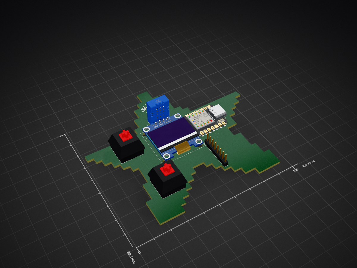
Starbie is a small motion-controlled digital pet built around a Seeed Studio XIAO ESP32-C3. It draws a one-bit pet on a 128×64 OLED, uses an MPU6050 to read tilt and shaking, and offers a four-way action menu.
Starbie is an open-source printed circuit board by notahuman404, from the notahuman404/AutoCADLearning repository on GitHub. It is a 2-layer board of 103.7 × 88.1 mm with 8 parts on 38 nets, routed with 27 tracks and 0 vias.
It is built around the DHT11. Its parts include 2 ICs, 2 connectors, 2 switches and 1 resistor. It belongs with the ESP32 and RISC-V boards of this library.
Starbie is a small motion-controlled digital pet built around a Seeed Studio XIAO ESP32-C3. It draws a one-bit pet on a 128×64 OLED, uses an MPU6050 to read tilt and shaking, and offers a four-way action menu. A DHT11 can provide temperature and humidity readings.
Concept render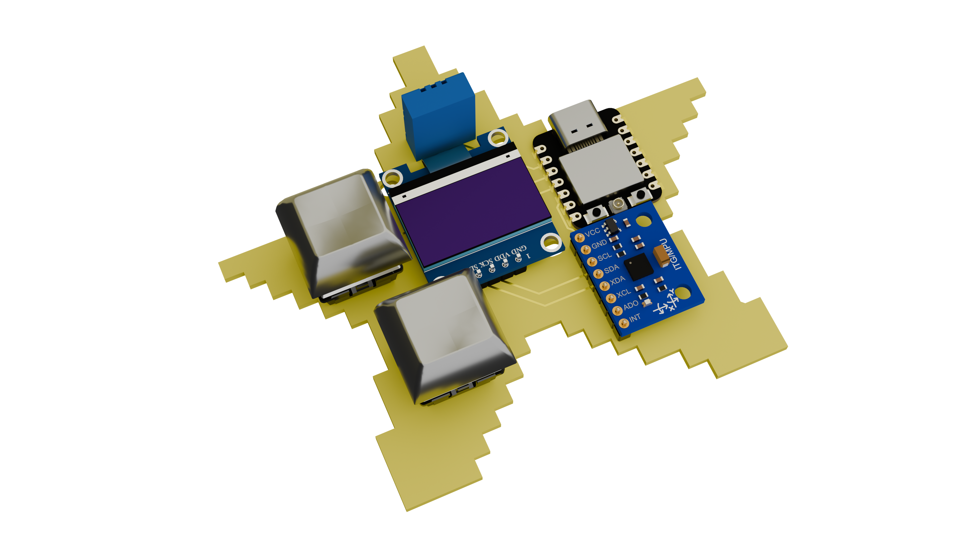 | 3D PCB render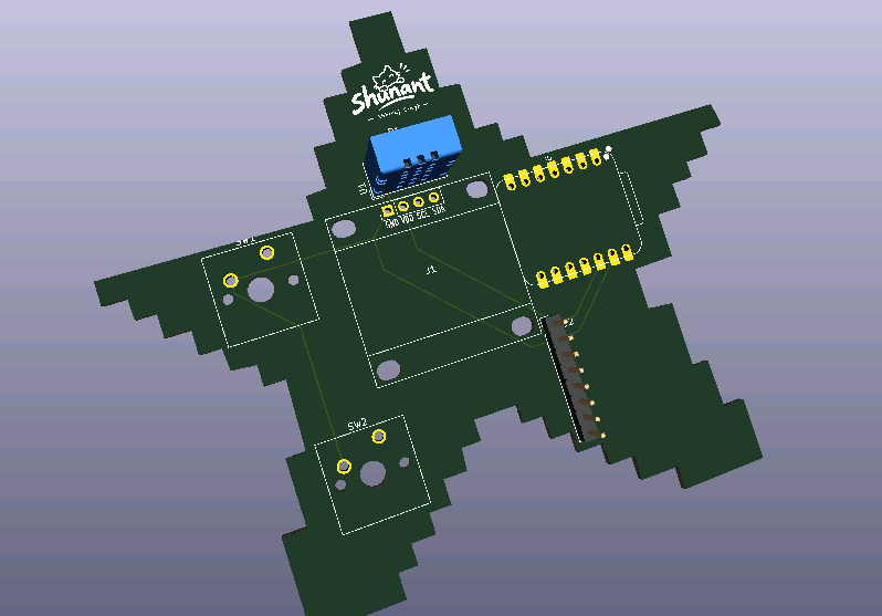 |
PCB layout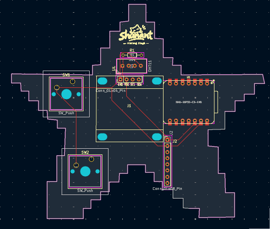 | Schematic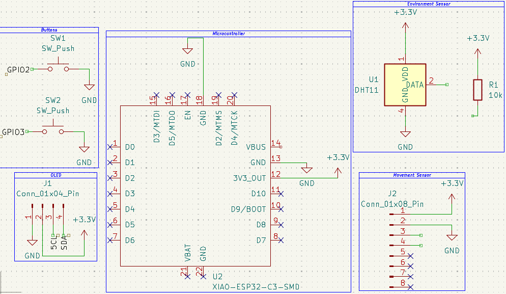 |
| Part | Role |
|---|---|
| Seeed Studio XIAO ESP32-C3 | Controller and firmware target |
| 0.96-inch 128×64 I²C OLED, SSD1306-compatible | Pet display |
| MPU6050 module (external via J2) | Tilt and shake sensing |
| DHT11 | Optional temperature and humidity sensing |
| 2 Cherry MX-compatible 1U switches | Menu/action and stats controls |
| 10 kΩ through-hole resistor | Listed as R1 in the schematic |
| Custom PCB | KiCad design in the starbie directory |
See BOM.csv for the current parts list. The guide pairs the XIAO ESP32-C3 symbol with the custom footprint ID Imported Parts:XIAO-ESP32-C6-DIP; the BOM preserves that assignment. The guide represents the MPU6050 module with a generic 1x08 connector: J2 is the board-mounted header and pins 1-4 carry +3.3V, GND, SCL, and SDA. The guide does not specify a particular breakout-board variant, so the BOM names it as an MPU6050 module connected via J2.
The firmware pin assignments are in Firmware/Starbie/Starbie.ino. OLED and MPU6050 share I²C.
| Device | XIAO connection | Notes |
|---|---|---|
| OLED SDA | D4 / GPIO6 | I²C address defaults to 0x3C |
| OLED SCL | D5 / GPIO7 | Shared I²C bus |
| MPU6050 SDA | D4 / GPIO6 | I²C address defaults to 0x68 |
| MPU6050 SCL | D5 / GPIO7 | Shared I²C bus |
| DHT11 data | D1 / GPIO3 | Optional; set USE_DHT11 to false if not fitted |
| Button 1 | D2 / GPIO4 | Opens the menu; confirms the selected action |
| Button 2 | D3 / GPIO5 | Shows or hides the stats screen |
Connect module power and ground according to the module labels and the schematic. Verify voltage and pin order before powering the board.
Button 1 opens the four-way menu. Tilt toward top for NAP, right for PLAY, bottom for FEED, or left for PET; press Button 1 again to confirm. Button 2 toggles stats. Shaking Starbie gives it a reaction and wakes it from a nap. The DHT11 can be disabled with USE_DHT11 if that sensor is not installed.
This project follows the Starbie Week 1 guide.
| Qty | Value | Footprint | References |
|---|---|---|---|
| 2 | SW_Push | Button_Switch_Keyboard:SW_Cherry_MX_1.00u_PCB | SW1, SW2 |
| 1 | 10k | Resistor_THT:R_Axial_DIN0204_L3.6mm_D1.6mm_P7.62mm_Horizontal | R1 |
| 1 | Conn_01x04_Pin | Imported Parts:Display_128x64_096_I2C | J1 |
| 1 | Conn_01x08_Pin | Connector_PinHeader_2.54mm:PinHeader_1x08_P2.54mm_Vertical | J2 |
| 1 | DHT11 | Sensor:Aosong_DHT11_5.5x12.0_P2.54mm | U1 |
| 1 | LOGO | logo:logo | G*** |
| 1 | XIAO-ESP32-C3-SMD | Imported Parts:XIAO-ESP32-C6-DIP | U2 |

lansidev/conveyor-belt
Miniature 3D printed conveyor belt for simulation and fun working with sensors, all controllable with Raspberry Pi


ebrithiljonas/OMG_PCB
All in One PCB for the OpenMQTTGateway Project

GeorgK/SniffingTrinket
A room climate monitor using the Adafruit Trinket Pro

bhaskar9980/Guardian
Guardian is an advanced, fully automated hydroponics system designed to optimize plant growth and maximize yield.

Twistx77/Firefly
Open WIFI-enabled RGB lamp with temperature, humidity, suspended air particles and eCO2 sensors.

unla-investigacion-desarrollo/ecosistema-iot
Antes de desarrollar el sistema final, realizamos una etapa de exploración donde investigamos y experimentamos con las siguientes tecnologías:
It measures 103.7 × 88.1 mm and has 2 copper layers, 1.6 mm thick.
8 parts, built around the DHT11. The full list of its parts is on this page, with links to each part's symbol and footprint where PCBKit's library has them.
From the notahuman404/AutoCADLearning repository on GitHub, at the commit this page was made from: the board is starbie/starbie.kicad_pcb and its schematic starbie/starbie.kicad_sch. PCBKit opens the board in the browser, with nothing to install.
Its repository states no licence, so its author keeps all rights: ask notahuman404 before reusing the design.