Skip to the content
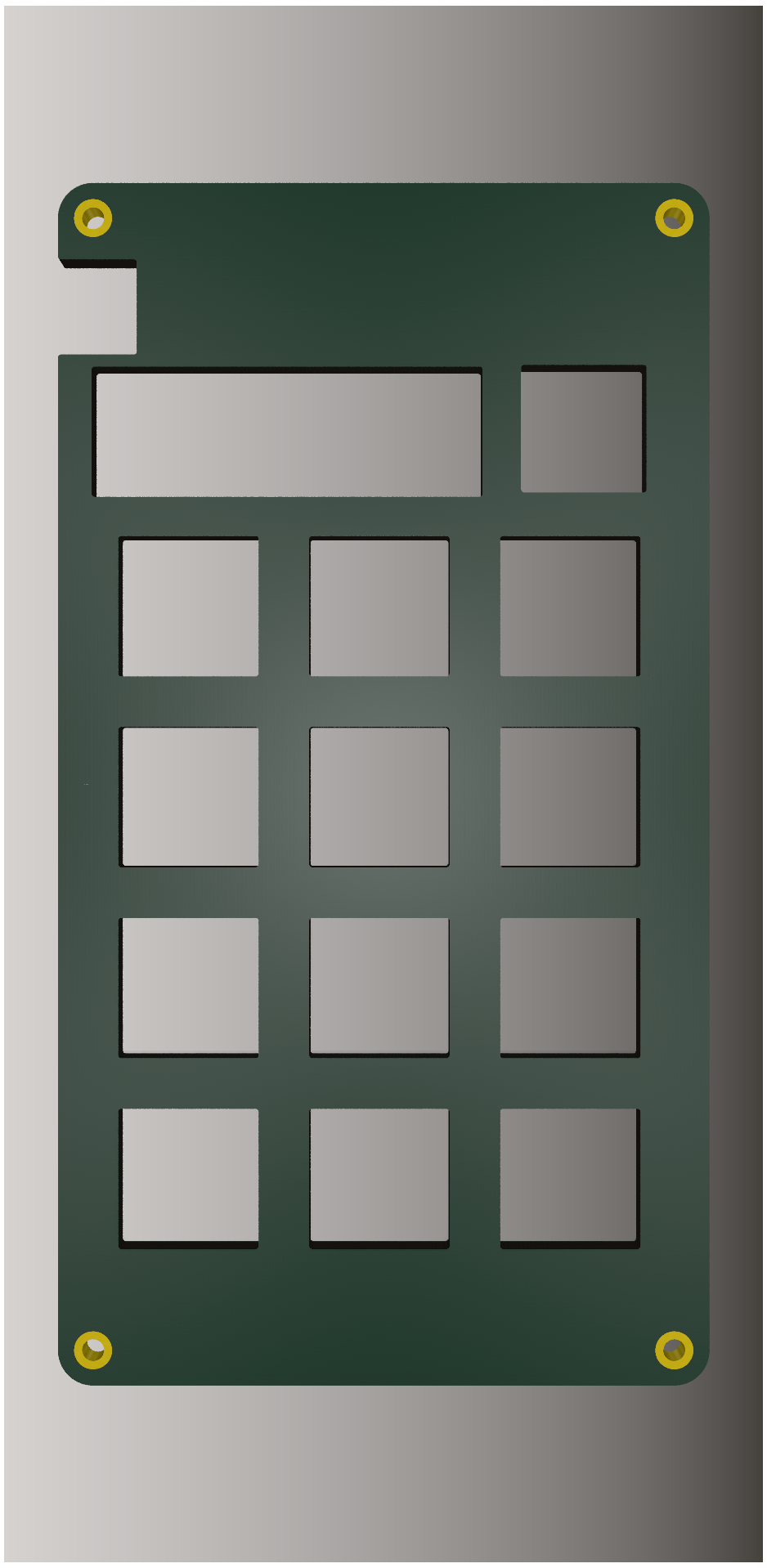
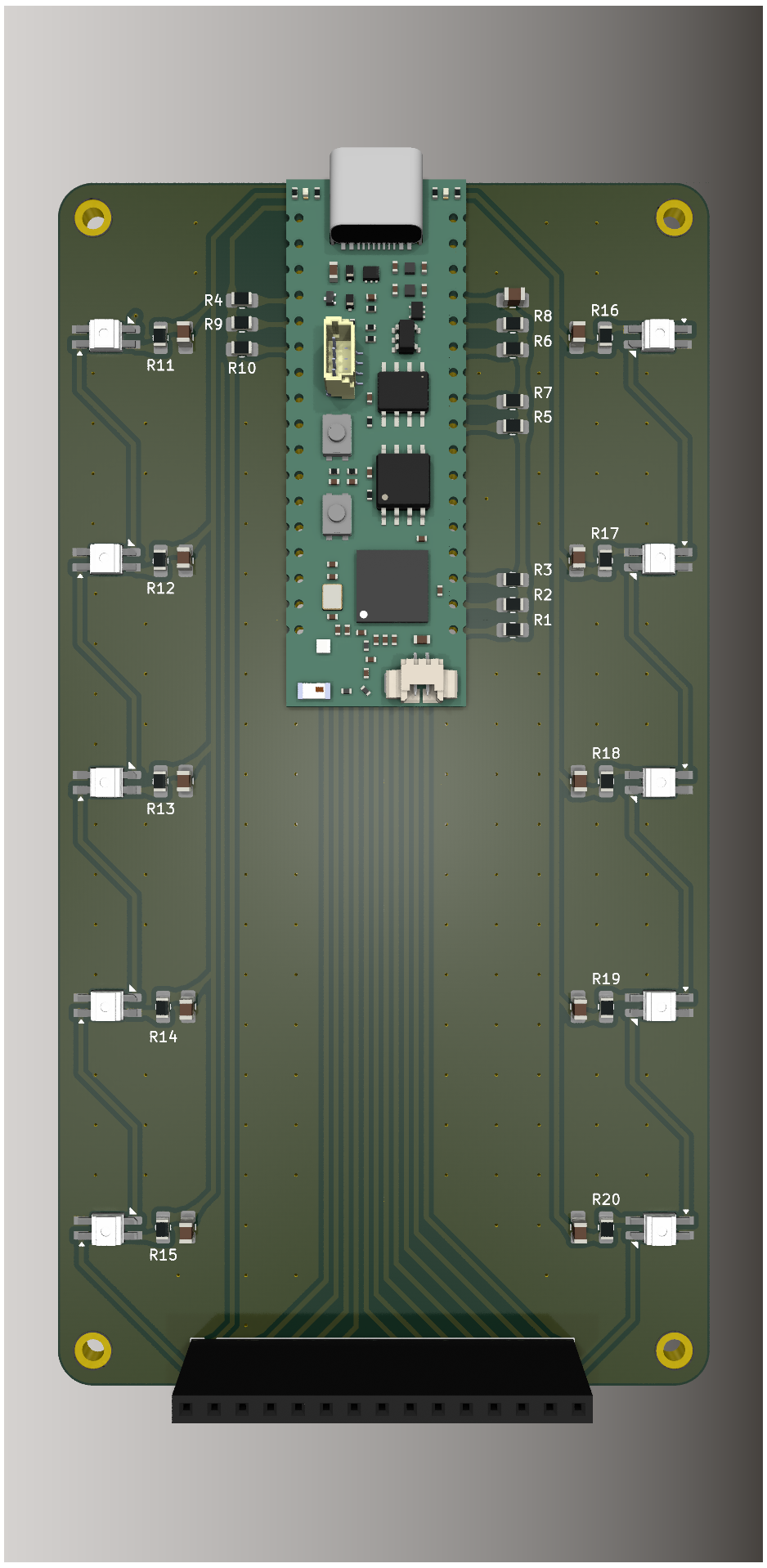
2 layers65 × 120 mmTop plate, the printed circuit board in 3D

This repository represents the final version submitted for my Bachelor's Thesis.

Size
65 × 120 mm
Copper layers
2
Thickness
1.6 mm
Parts
4
Nets
4
Pads
4
Tracks, vias
0, 0
Routed
Not yet
KiCad
KiCad 9.0 (file 20241229)
Created
28 Jul 2025
Updated
4 Jul 2026

Overview

Top plate is an open-source printed circuit board by not-sample-text, from the not-sample-text/Proiect-Licenta repository on GitHub. It is a 2-layer board of 65 × 120 mm with 4 parts on 4 nets.

README

README.md

Repository Archived

This repository represents the final version submitted for my Bachelor's Thesis.

Active development for this project has moved to ApexPad. Please refer to the new repository for the most recent updates, bug fixes, and feature development.


PROS3 Macropad: A Fully-Programmable Custom Mechanical Macropad

The PROS3 Macropad is a versatile, open-source 12-key macropad built around the powerful ESP32-S3. Designed as a university thesis project, it features a rotary encoder, OLED display, RGB underglow, and a complete software ecosystem for deep customization.


Gallery

A collection of renders showcasing the hardware.

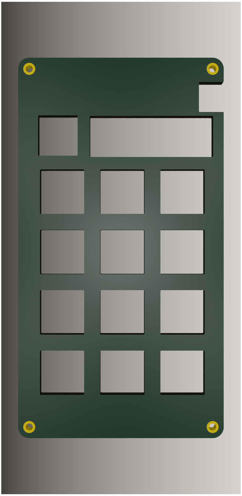
Top PlateTop Plate (Angled)
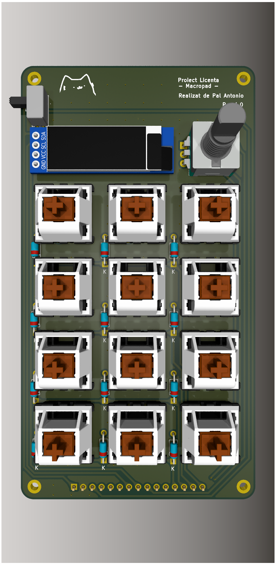
Top ViewTop (Angled)
Top RenderTop Render (Angled)!
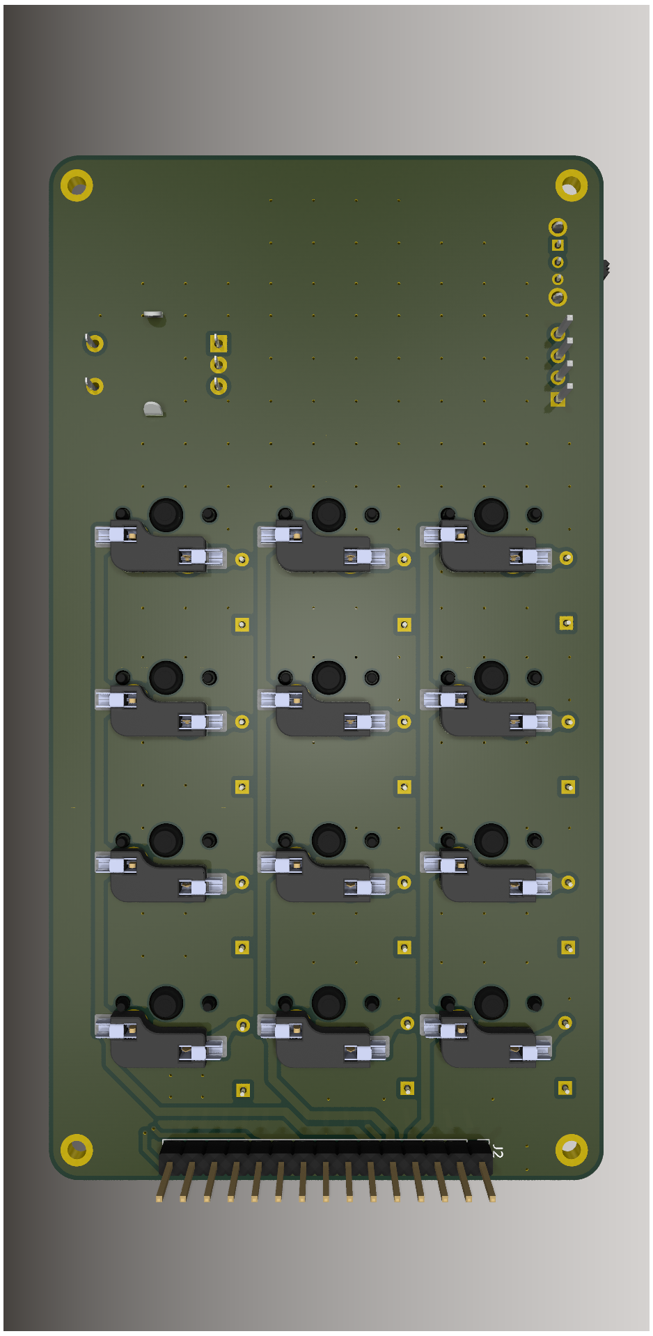
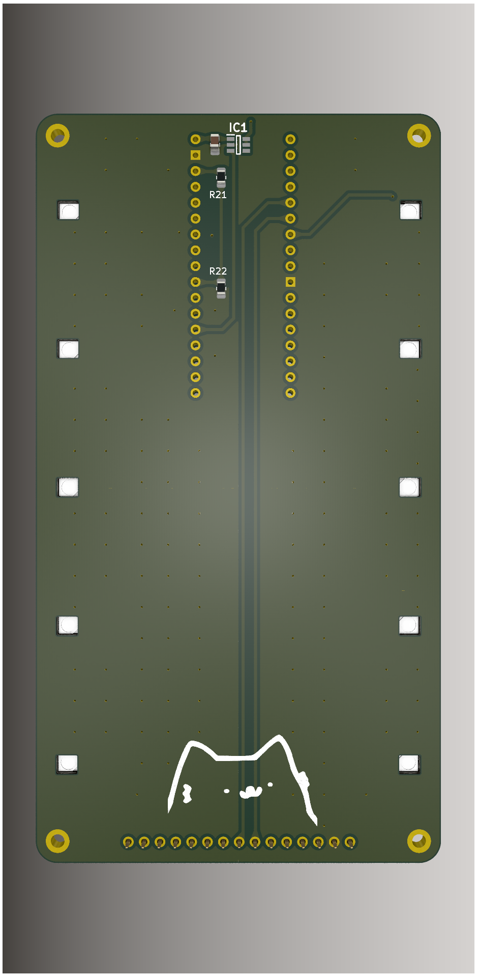
Bottom RenderBottom (Angled)
Bottom RenderBottom Render (Angled)

About The Project

This repository contains the complete engineering files (hardware, firmware, and software) for a highly programmable macropad designed to streamline digital workflows.

The project is built on three pillars:

  1. Hardware: A custom two-part PCB design with a 3D-printable case. It's designed for assembly by hobbyists with through-hole components and hot-swap sockets.
  2. Firmware: Custom C++ code running on the ESP32-S3. It manages input, the OLED display, lighting, and communication with the host computer.
  3. Software Suite: A powerful combination of a static web-based configurator (for visually creating keymaps) and a headless Python-based background daemon (for executing complex OS-level actions via a system tray UI).

This architecture allows the macropad to go beyond simple keystrokes and act as a powerful automation tool.

For a complete technical deep-dive, please see the Full Technical Documentation. (Pentru documentația în limba română, consultați acest document).


Features

  • 12 Hot-Swappable Mechanical Keys: Customize your macropad with any MX-style switches, no soldering required.
  • Rotary Encoder with Push-Button: Perfect for volume control, scrolling through timelines, or cycling through layers.
  • OLED Display: Get real-time feedback on your current layer, connection status, and more.
  • Powerful Layering System: Switch between 4 distinct layers to multiply your available keys.
  • Dual-Mode Actions:
    • HID Mode: Send standard keystrokes and shortcuts that work on any OS without drivers.
    • Host Control Mode: Trigger complex actions on your computer—like launching native apps or executing shell scripts—using the auto-discovering background daemon.
  • Web-Based Configurator: A zero-dependency, browser-based UI for remapping keys, creating macros, and configuring lighting. Features a guided interactive tour and smart JSON export.
  • RGB Underglow: 10 addressable RGB LEDs for brilliant lighting effects, managed by FastLED.
  • Dual Connectivity: Seamlessly switch between a wired USB-C connection and wireless Bluetooth/BLE HID.

Getting Started

  1. Build the Hardware: Use the KiCad files in the hardware/ directory to fabricate the PCBs and source the components from the Bill of Materials.
  2. Flash the Firmware: Use PlatformIO to compile and upload the firmware from the firmware/ directory to the ESP32-S3.
  3. Configure Your Layout: Access the Web Configurator (locally or via GitHub Pages) to design your custom keymaps and export the config.json file to your Downloads folder.
  4. Run the Host Daemon: Download the standalone executable from the Releases page (or run the Python script). It automatically connects to the hardware, detects your config file, and runs invisibly in your system tray to unlock the command and launcher layers.

For a detailed, step-by-step guide, please refer to the Complete User Workflow section in the documentation.


Acknowledgements

This project was made possible by the following open-source projects and communities:

  • ScottoKeebs: For the KiCad libraries and footprints for mechanical keyboards.
  • The Mechanical Keyboard Community: For providing a constant source of inspiration and knowledge.

License

The hardware and software are provided as-is under a permissive license. This project includes components from third-party libraries which are subject to their own licenses. Please see the individual source files for more details.

Parts

4
QtyValueFootprintReferences
4MountingHole_PadMountingHole:MountingHole_2.2mm_M2_DIN965_PadH1, H2, H3, H4

More from not-sample-text/Proiect-Licenta

2
  • 2 layers65 × 120 mmBottom, the printed circuit board in 3D

    Bottom

    not-sample-text/Proiect-Licenta

    This repository represents the final version submitted for my Bachelor's Thesis.

    52 parts1
  • 2 layers65 × 120 mmTop, the printed circuit board in 3D

    Top

    not-sample-text/Proiect-Licenta

    This repository represents the final version submitted for my Bachelor's Thesis.

    33 parts1

Similar boards

  • 2 layers18.5 × 26 mm24g2usb rp2350zero, the printed circuit board in 3D

    24g2usb rp2350zero

    joypad-ai/joypad-os

    Universal controller firmware for building adapters, dongles, and custom controllers.

    4 parts1.7kApache-2.0
  • 2 layers116 × 33 mm966595-1 and 963356-1, the printed circuit board in 3D

    966595-1 and 963356-1

    rusefi/rusefi

    rusefi - GPL internal combustion engine control unit

    4 parts1.2k
  • 2 layers19 × 18 mmDaughter board, the printed circuit board in 3D

    Daughter board

    hackclub/OnBoard

    💡 Join 1,000 teenagers and make your first PCB with a $100 grant!

    4 parts915
  • 2 layers24.8 × 24.8 mmNrf24 breakout, the printed circuit board in 3D

    Nrf24 breakout

    tardate/LittleArduinoProjects

    a collection of "Little Electronic & Arduino Projects", most involving electronics or an Arduino in one way or another!

    4 parts803MIT
  • 2 layers26 × 20 mmCap chain, the printed circuit board in 3D

    Cap chain

    drandyhaas/KiCadRoutingTools

    A set of Python/Rust tools to aid routing in KiCad

    4 parts744MIT
  • 2 layers34.7 × 20 mmXG Station Power MSI, the printed circuit board in 3D

    XG Station Power MSI

    osy/XG_Mobile_Station

    Open source eGPU dock for ROG Ally and ROG Flow

    4 parts712CC-BY-4.0
  • 2 layers20.3 × 24.5 mmJack power input, the printed circuit board in 3D

    Jack power input

    Luos-io/luos_engine

    Open-source and real-time orchestrator for cyber-physical-systems, to easily design, test and deploy embedded applications and digital twins.

    4 parts546MIT

Questions

How big is the Top plate PCB?

It measures 65 × 120 mm and has 2 copper layers, 1.6 mm thick.

What parts does the Top plate use?

4 parts. The full list of its parts is on this page, with links to each part's symbol and footprint where PCBKit's library has them.

Where can I download the Top plate KiCad files?

From the not-sample-text/Proiect-Licenta repository on GitHub, at the commit this page was made from: the board is hardware/pcb/top-plate/top-plate.kicad_pcb and its schematic hardware/pcb/bottom/bottom.kicad_sch. PCBKit opens the board in the browser, with nothing to install.

Can I use the Top plate design in my own project?

Its repository states no licence, so its author keeps all rights: ask not-sample-text before reusing the design.