


4 layers140 × 81 mm

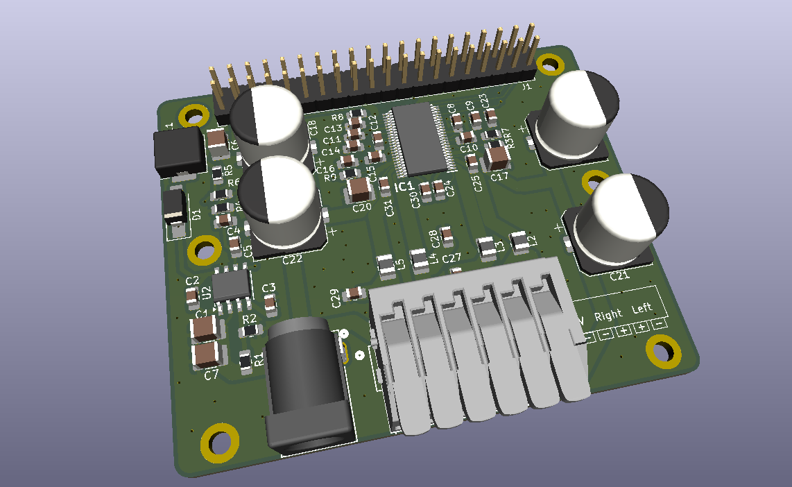
A small, power-efficient AirPlay 2 network amplifier. A custom stereo class-D amplifier HAT sits on a Radxa Zero 3E running NixOS and shairport-sync, so any Apple device (or anything that speaks AirPlay 2) can stream…
Stereo is an open-source printed circuit board by noranraskin, from the noranraskin/stereo-hat repository on GitHub, published under the GPL-3.0 licence. It is a 2-layer board of 68 × 56 mm with 57 parts on 68 nets, routed with 344 tracks and 150 vias.
It is built around the TAS5756MDCAR, B340 and DC-005-A200. Its parts include 31 capacitors, 9 resistors, 5 inductors, 3 connectors and 2 ICs.


A small, power-efficient AirPlay 2 network amplifier. A custom stereo class-D amplifier HAT sits on a Radxa Zero 3E running NixOS and shairport-sync, so any Apple device (or anything that speaks AirPlay 2) can stream straight to a pair of passive speakers over Ethernet.
 iPhone / Mac ──AirPlay 2──▶ Ethernet ──▶ Radxa Zero 3E (NixOS, shairport-sync)
                                              │  I2S (pins 12, 35, 38, 40)
                                              │  I2C (pins 3, 5)
                                              ▼
 12–24 V DC ──▶ HAT ──▶ TPS54232 buck ──5 V──▶ SBC (via header pins 2/4)
                 │                      SBC 3.3 V ──▶ TAS5756M logic
└──────────── VIN ───▶ TAS5756M power stage ──▶ L / R speakersshairport-sync is built with AirPlay 2 support, and nqptp handles AirPlay 2 timing.The HAT is pin-compatible with the HiFiBerry Amp2, so it also works on a Raspberry Pi with the HiFiBerry drivers.
[!IMPORTANT] !!IMPORTANT!! USING A SELF ASSEMBLED HAT WITH A RADXA AND NIXOS IS SOMEWHAT UNCONVENTIONAL. IF YOU USE ANY OTHER SETUP I CANNOT OFFER SUPPORT. THIS IS A HOBBY PROJECT, NOT A PRODUCT.
| Path | What it is |
|---|---|
kicad/ | KiCad 10 project for the HAT: schematics, PCB, custom symbols, footprints and 3D models |
kicad/bom/ibom.html | Interactive BOM. Open it in a browser while placing parts |
kicad/datasheets/ | Datasheets for the TAS5756M and TPS54232 |
kicad/fabrication-toolkit-options.json | Settings for the KiCad Fabrication Toolkit plugin (Gerbers, BOM, placement files) |
nix/configuration.nix | Base NixOS system config |
nix/audio-hat.nix | Device tree overlay that enables I2S, I2C and the TAS5756M sound card |
nix/airplay.nix | shairport-sync (AirPlay 2), nqptp and Avahi |
imgs/ | Render and schematic exports used in this README |
| Sheet | |
|---|---|
| Top level / amplifier | imgs/stereo.svg |
| 5 V power supply | imgs/power.svg |
| SBC header and connectors | imgs/io.svg |
Only these header pins are used. Everything else is left unconnected.
| Pin | Net | Purpose |
|---|---|---|
| 1, 17 | 3.3V | Logic supply for the TAS5756M, from the SBC |
| 2, 4 | 5V | Output from the HAT's buck converter, powers the SBC |
| 3 | SDA | I2C data |
| 5 | SCL | I2C clock |
| 7 | SPK_MUTE | Amplifier mute (drive high to play) |
| 12 | SCLK | I2S bit clock |
| 35 | LRCK/FS | I2S word clock |
| 38 | ICSDOUT | I2S data from amp to SBC |
| 40 | ICSDIN | I2S data from SBC to amp |
| 6, 9, 14, 20, 25, 30, 34, 39 | GND | Ground |
kicad/stereo.kicad_pro in KiCad 10.kicad/fabrication-toolkit-options.json). It writes Gerbers, drill files, a BOM and a placement file to kicad/production/.kicad/bom/ibom.html to place the parts.Get a working aarch64 NixOS install booting on the Radxa Zero 3E with Ethernet up. Then generate the hardware config on the device:
sudo nixos-generate-configThis creates /etc/nixos/hardware-configuration.nix, which configuration.nix imports. It is specific to each device and not part of this repo.
Copy the three files from nix/ into /etc/nixos/ on the device, then edit them:
configuration.nix: add your SSH public key to users.users.nixos.openssh.authorizedKeys.keys, and set networking.hostName and time.timeZone.airplay.nix: change "Name of Stereo" to the name you want to see in the AirPlay menu. If you build several speakers, give each one a unique name and hostname.Then build and switch:
sudo nixos-rebuild switchReboot once so the device tree overlay is loaded.
audio-hat.nix adds a device tree overlay that:
i2s3 controller on header pins 12 / 35 / 38 / 40;i2c3 on pins 3 / 5 and declares the TAS5756M at both possible I2C addresses (0x4c and 0x4d), so the board works whatever the address strap is set to;TAS5756M, so the ALSA device is always hw:TAS5756M;GPIO3_C4 (header pin 7, SPK_MUTE) high, so the amplifier is unmuted at boot.It also loads the snd_soc_pcm512x driver, which supports the TAS5756M.
airplay.nix builds shairport-sync with AirPlay 2 enabled, runs nqptp for AirPlay 2 timing, enables Avahi (mDNS) so the speaker shows up on your network, and trusts the end0 Ethernet interface in the firewall.
# The TAS5756M should be bound to its driver (shows "UU" at 4c or 4d)
i2cdetect -l
sudo i2cdetect -y <bus number of i2c3>

# The sound card should be listed
aplay -l

# Play a test tone on both channels (keep the volume low!)
speaker-test -D hw:TAS5756M -c 2 -t sine

# Follow the AirPlay service logs
journalctl -fu shairport-sync
The speaker should now show up in the AirPlay menu of any device on the same network.
Since the HAT is pin-compatible with the HiFiBerry Amp2, a Raspberry Pi can use the HiFiBerry driver. In /boot/firmware/config.txt:
dtparam=audio=off
dtoverlay=hifiberry-dacplus
gpio=4=op,dh
gpio=4=op,dh drives header pin 7 (GPIO4) high to unmute the amplifier. On newer Raspberry Pi OS kernels the overlay may be named hifiberry-dacplus-std. Then install shairport-sync with AirPlay 2 support and point it at the sndrpihifiberry card.
| Qty | Value | Footprint | References |
|---|---|---|---|
| 6 | 1µF | Capacitor_SMD:C_0805_2012Metric_Pad1.18x1.45mm_HandSolder | C8, C11, C12, C13, C14, C23 |
| 4 | 0.22µF | Capacitor_SMD:C_0805_2012Metric_Pad1.18x1.45mm_HandSolder | C24, C25, C30, C31 |
| 4 | 0.68µF | Capacitor_SMD:C_0805_2012Metric_Pad1.18x1.45mm_HandSolder | C26, C27, C28, C29 |
| 4 | 2.2µF | Capacitor_SMD:C_0805_2012Metric_Pad1.18x1.45mm_HandSolder | C9, C10, C15, C16 |
| 4 | 220µF | Capacitor_SMD:CP_Elec_10x10 | C18, C19, C21, C22 |
| 4 | 22µF | Capacitor_SMD:C_1210_3225Metric_Pad1.33x2.70mm_HandSolder | C1, C7, C17, C20 |
| 3 | 150k | Resistor_SMD:R_0805_2012Metric_Pad1.20x1.40mm_HandSolder | R3, R8, R9 |
| 3 | L | Inductor_SMD:L_1008_2520Metric_Pad1.43x2.20mm_HandSolder | L3, L4, L5 |
| 1 | 0.1µF | Capacitor_SMD:C_0805_2012Metric_Pad1.18x1.45mm_HandSolder | C2 |
| 1 | 1.96k | Resistor_SMD:R_0805_2012Metric_Pad1.20x1.40mm_HandSolder | R6 |
| 1 | 10.2k | Resistor_SMD:R_0805_2012Metric_Pad1.20x1.40mm_HandSolder | R5 |
| 1 | 10nF | Capacitor_SMD:C_0805_2012Metric_Pad1.18x1.45mm_HandSolder | C3 |
| 1 | 10pF | Capacitor_SMD:C_0805_2012Metric_Pad1.18x1.45mm_HandSolder | C5 |
| 1 | 180pF | Capacitor_SMD:C_0805_2012Metric_Pad1.18x1.45mm_HandSolder | C4 |
| 1 | 2601-1106 | CONN3_2601-1103_WAG:CONN3_2601-1106_WAG | J5 |
| 1 | 390k | Resistor_SMD:R_0805_2012Metric_Pad1.20x1.40mm_HandSolder | R7 |
| 1 | 47µF | Capacitor_SMD:C_1210_3225Metric_Pad1.33x2.70mm_HandSolder | C6 |
| 1 | 6.8µH | Inductor_SMD:L_Changjiang_FXL0630 | L1 |
| 1 | 665k | Resistor_SMD:R_0805_2012Metric_Pad1.20x1.40mm_HandSolder | R1 |
| 1 | 75k | Resistor_SMD:R_0805_2012Metric_Pad1.20x1.40mm_HandSolder | R4 |
| 1 | 84.5k | Resistor_SMD:R_0805_2012Metric_Pad1.20x1.40mm_HandSolder | R2 |
| 1 | B340 | Diode_SMD:D_SMA_Handsoldering | D1 |
| 1 | DC-005-A200 | DC-005-A200:JACK_DC-005-A200_XNP | J2 |
| 1 | L | Inductor_SMD:L_1008_2520Metric | L2 |
| 1 | Raspberry_Pi_4 | Connector_PinHeader_2.54mm:PinHeader_2x20_P2.54mm_Vertical | J1 |
| 1 | TAS5756MDCAR | TAS5756M:SOP50P810X120-49N | IC1 |
| 1 | TPS54232DR | Package_SO:TI_SO-PowerPAD-8_ThermalVias | U2 |
The 51 most common of 57 parts.

florolf/lab-automation
Plugs into relay and can be used to provide switchable 5V USB power to downstream devices.


anandijain/clock2-kicad
I'm not sure why the placement of the resistors, caps, and 555s (and a few other things) is wrong in the 3D file.

Pegoku/LED-Controller-PCB
A simple monochromatic LED controller for Home Assistant

NoBlackBoxes/LastBlackBox
A course for brains interested in brains (not tools interested in tools)

K-0hm/Chessboard
Code for a chessboard with light and capacitance Touch Sensors.
It measures 68 × 56 mm and has 2 copper layers, 1.6 mm thick.
57 parts, built around the TAS5756MDCAR, B340 and DC-005-A200. The full list of its parts is on this page, with links to each part's symbol and footprint where PCBKit's library has them.
From the noranraskin/stereo-hat repository on GitHub, at the commit this page was made from: the board is kicad/stereo.kicad_pcb and its schematic kicad/io.kicad_sch. PCBKit opens the board in the browser, with nothing to install.
Its repository publishes it under the GPL-3.0 licence: you may reuse it on that licence's terms (keep the author's notice, and for a copyleft licence share your changes alike).