

2 layers160 × 100 mm

 nophead/Blinder9
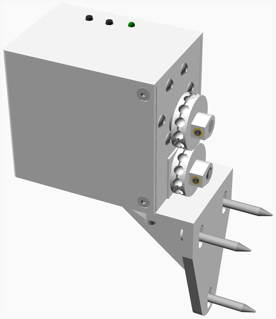
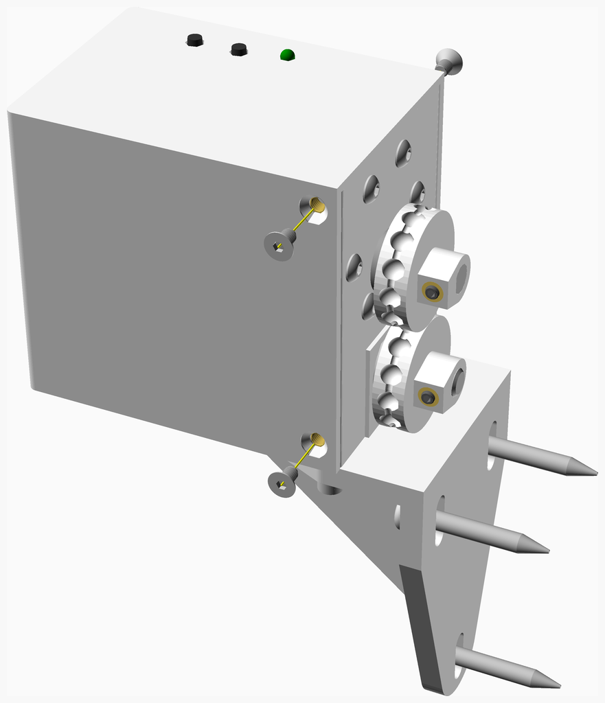
Tasmota roller blind open / close mechanism
Blinder is an open-source printed circuit board by nophead, from the nophead/Blinder repository on GitHub, published under the GPL-3.0 licence. It is a 4-layer board of 42 × 45 mm with 25 parts on 33 nets, routed with 192 tracks and 12 vias.
It is built around the ESP-12F and L6203. Its parts include 8 resistors, 5 capacitors, 5 connectors, 3 ICs and 2 switches. It belongs with the home automation and IoT boards and the ESP8266 boards of this library.
[blocked]
Tasmota roller blind open / close mechanism
[blocked]
| Switch Slide | Rod | Base | Motor | Bracket | Blinder PCB | Cover | Main | TOTALS | |
|---|---|---|---|---|---|---|---|---|---|
| Vitamins | |||||||||
| . | . | 2 | . | . | . | . | . | 2 | Ball bearing 686ZZ 6mm x 13mm x 5mm |
| . | . | . | . | . | 1 | . | . | 1 | ESP-12F ESP8266 WiFi module |
| 2 | . | 2 | . | . | . | . | . | 4 | Heatfit insert M2 x 4mm |
| . | . | 10 | 1 | . | . | . | . | 11 | Heatfit insert M3 x 3mm |
| . | . | . | . | . | 1 | . | . | 1 | JST PH connector 2 way |
| . | . | . | . | . | 2 | . | . | 2 | JST PH connector 3 way |
| . | . | . | . | . | 1 | . | . | 1 | LED 3 mm green |
| . | . | . | . | . | 1 | . | . | 1 | MULTIWATT11 L6203 |
| 1 | . | 1 | . | . | . | . | . | 2 | Microswitch DM1-00P-110-3 |
| . | . | . | . | . | 1 | . | . | 1 | Molex KK header 2 way |
| . | . | . | . | . | 1 | . | . | 1 | Molex KK housing 2 way |
| . | . | . | . | . | . | 1 | . | 1 | Nut M3 x 2.4mm nyloc |
| . | . | 1 | . | . | . | . | . | 1 | Nut M8 x 6.5mm brass |
| . | . | . | . | . | 1 | . | . | 1 | PCB Blinder |
| . | . | . | . | . | 2 | . | . | 2 | SMD capacitor 0805 100n |
| . | . | . | . | . | 2 | . | . | 2 | SMD capacitor 0805 15n |
| . | . | . | . | . | 1 | . | . | 1 | SMD capacitor 0805 220n |
| . | . | . | . | . | 5 | . | . | 5 | SMD resistor 0805 10K 0.125W |
| . | . | . | . | . | 2 | . | . | 2 | SMD resistor 0805 1K 0.125W |
| . | . | . | . | . | 1 | . | . | 1 | SMD resistor 0805 2K2 0.125W |
| 2 | . | 2 | . | . | . | . | . | 4 | Screw M2 cap x 10mm |
| . | . | 1 | . | . | . | . | . | 1 | Screw M3 cap x 5mm |
| . | . | . | . | 3 | . | . | . | 3 | Screw M3 cap x 8mm |
| . | . | . | . | . | . | . | 4 | 4 | Screw M3 cs cap x 5mm |
| . | . | . | . | . | . | 1 | . | 1 | Screw M3 cs cap x 12mm |
| . | . | . | 6 | . | . | . | . | 6 | Screw M3 dome x 12mm |
| . | . | 2 | 1 | . | . | . | . | 3 | Screw M3 grub x 5mm |
| . | . | . | . | 3 | . | . | . | 3 | Screw No8 pan wood x 30mm |
| . | . | . | . | . | 2 | . | . | 2 | Square button 6mm |
| . | 1 | . | . | . | . | . | . | 1 | Threaded rod M8 x 79mm - not shown |
| . | . | . | . | . | 1 | . | . | 1 | Ultra Small 3A buck regulator |
| 2 | . | 2 | . | . | . | . | . | 4 | Washer M2 x 5mm x 0.3mm |
| . | . | 1 | . | 3 | . | 1 | . | 5 | Washer M3 x 7mm x 0.5mm |
| . | . | . | . | 3 | . | . | . | 3 | Washer M5 x 10mm x 1mm |
| . | . | 2 | . | . | . | . | . | 2 | Washer spring M6 x 1.9mm |
| 2 | . | 2 | . | . | . | . | . | 4 | Washer star M2 x 0.3mm |
| . | . | 1 | . | . | . | . | . | 1 | Washer star M3 x 0.5mm |
| 9 | 1 | 29 | 8 | 12 | 25 | 3 | 4 | 91 | Total vitamins count |
| 3D printed parts | |||||||||
| . | . | 1 | . | . | . | . | . | 1 | base.stl |
| . | . | . | . | 1 | . | . | . | 1 | bracket.stl |
| . | . | . | . | . | . | 1 | . | 1 | cover.stl |
| . | . | 1 | . | . | . | . | . | 1 | idler.stl |
| . | . | . | 1 | . | . | . | . | 1 | pulley.stl |
| . | . | 1 | . | . | . | . | . | 1 | retainer.stl |
| 1 | . | . | . | . | . | . | . | 1 | switch_slide.stl |
| 1 | . | 3 | 1 | 1 | . | 1 | . | 7 | Total 3D printed parts count |
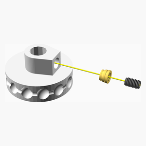
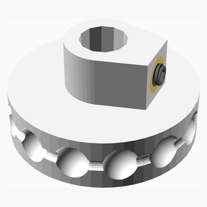
[blocked]
| Qty | Description |
|---|---|
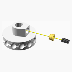
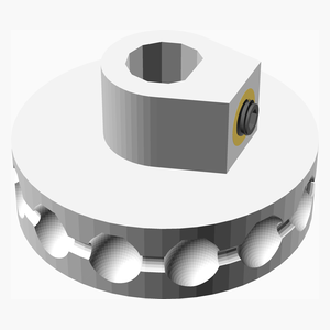
| 1 | Heatfit insert M3 x 3mm |
| 1 | Screw M3 grub x 5mm |
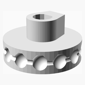
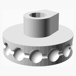
| 1 x pulley.stl |
|---|
 |
[blocked]
| Qty | Description |
|---|---|
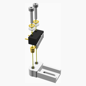
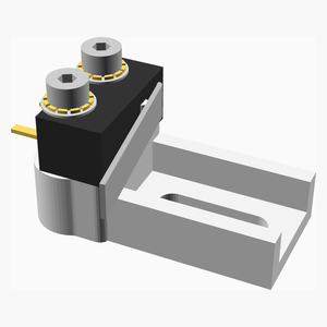
| 2 | Heatfit insert M2 x 4mm |
| 1 | Microswitch DM1-00P-110-3 |
| 2 | Screw M2 cap x 10mm |
| 2 | Washer M2 x 5mm x 0.3mm |
| 2 | Washer star M2 x 0.3mm |
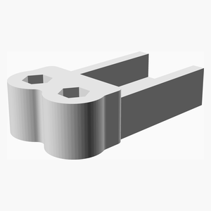
| 1 x switch_slide.stl |
|---|
 |
[blocked]
| Qty | Description |
|---|---|
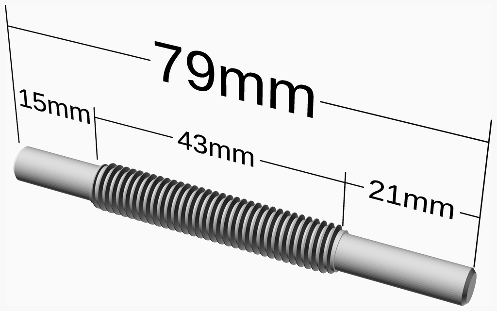
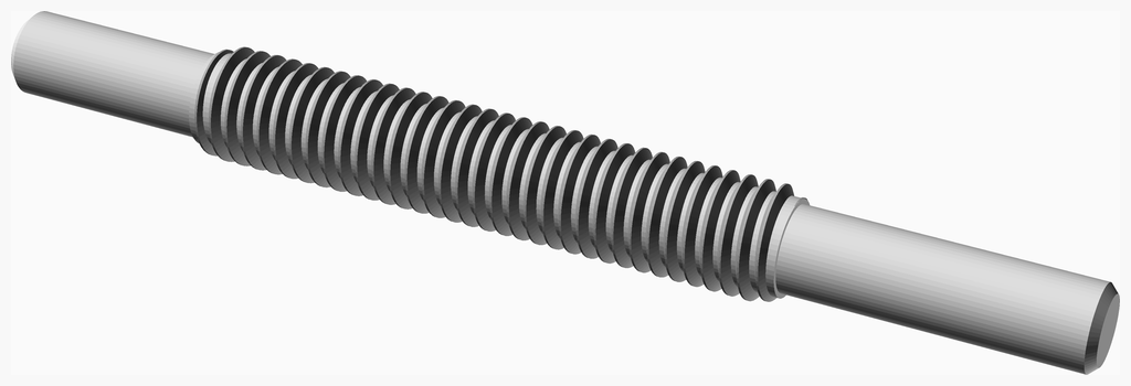
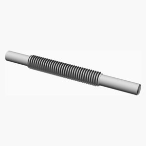
| 1 | Threaded rod M8 x 79mm - not shown |
[blocked]
| Qty | Description |
|---|---|
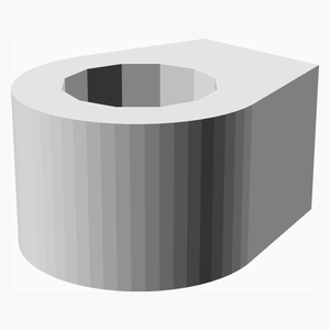
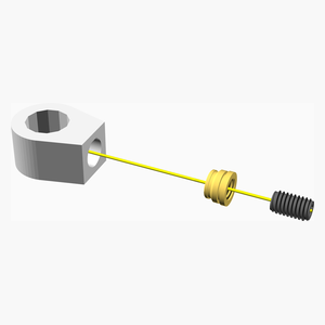
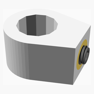
| 1 | Heatfit insert M3 x 3mm |
| 1 | Screw M3 grub x 5mm |
| 1 x retainer.stl |
|---|
 |
[blocked]
| Qty | Description |
|---|---|
| 1 | Heatfit insert M3 x 3mm |
| 1 | Screw M3 grub x 5mm |
| 1 x idler.stl |
|---|
 |
[blocked]
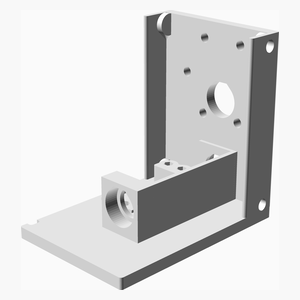
| Qty | Description |
|---|---|
| 2 | Ball bearing 686ZZ 6mm x 13mm x 5mm |
| 2 | Heatfit insert M2 x 4mm |
| 8 | Heatfit insert M3 x 3mm |
| 1 | Microswitch DM1-00P-110-3 |
| 1 | Nut M8 x 6.5mm brass |
| 2 | Screw M2 cap x 10mm |
| 1 | Screw M3 cap x 5mm |
| 2 | Washer M2 x 5mm x 0.3mm |
| 1 | Washer M3 x 7mm x 0.5mm |
| 2 | Washer spring M6 x 1.9mm |
| 2 | Washer star M2 x 0.3mm |
| 1 | Washer star M3 x 0.5mm |
| 1 x base.stl |
|---|
 |
| 1 x idler_assembly | 1 x retainer_assembly | 1 x rod_assembly |
|---|---|---|
| |  |
| 1 x switch_slide_assembly |
|---|
|
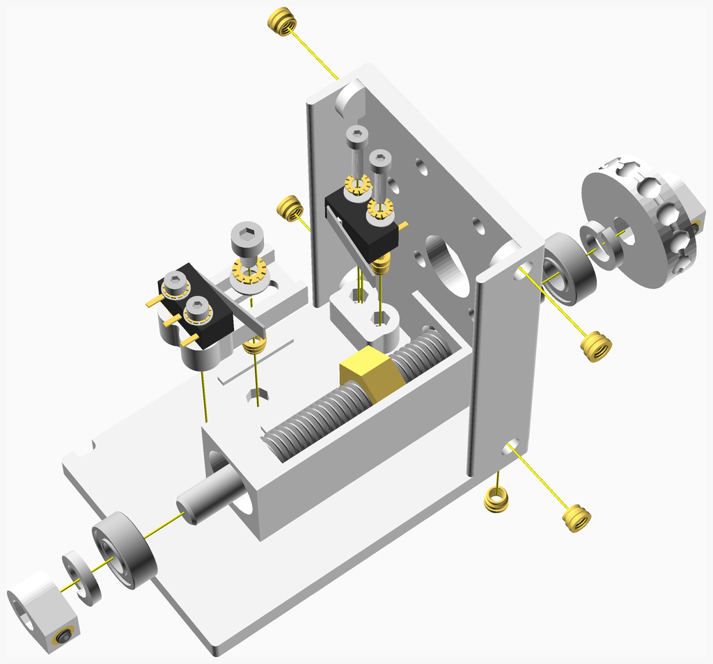
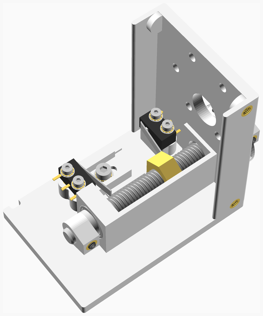
[blocked]
| Qty | Description |
|---|---|
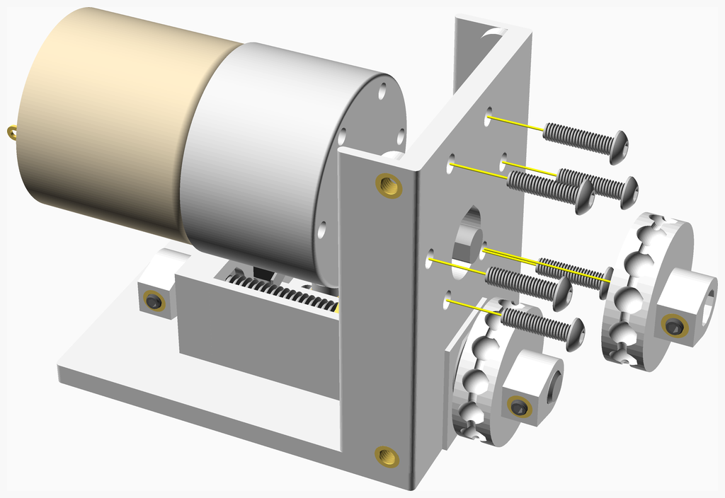
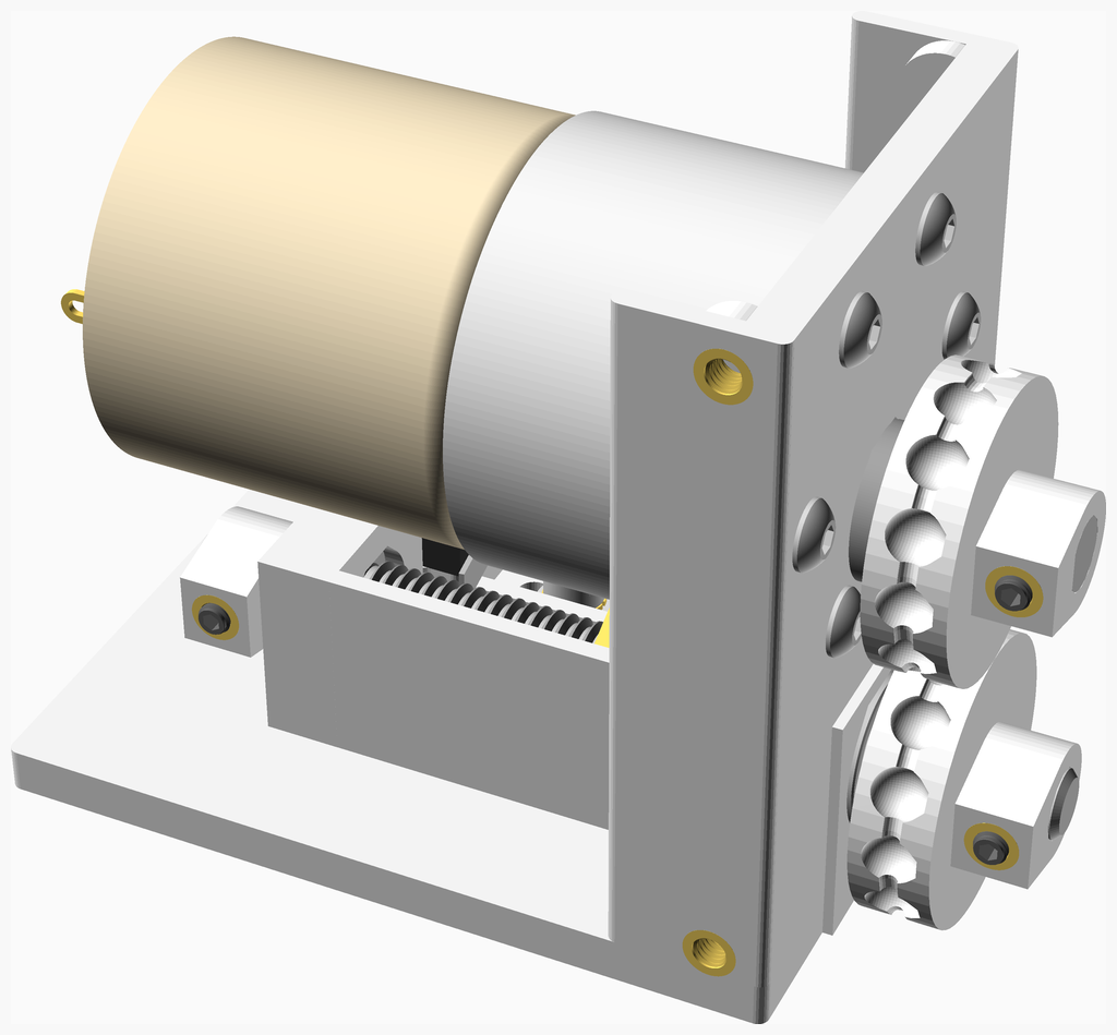
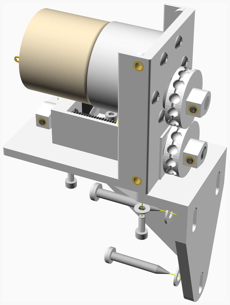
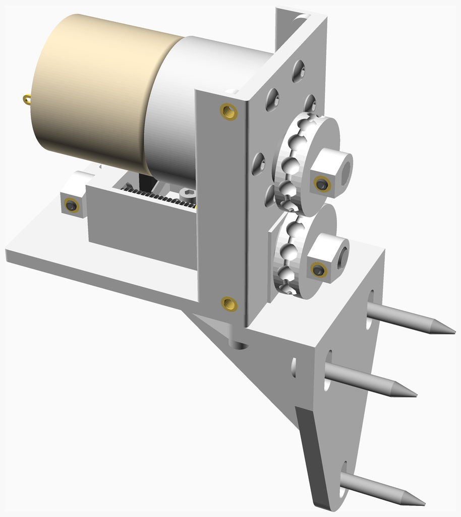
| 6 | Screw M3 dome x 12mm |
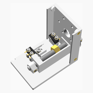
| 1 x base_assembly | 1 x pulley_assembly |
|---|---|
 | |
[blocked]
| Qty | Description |
|---|---|
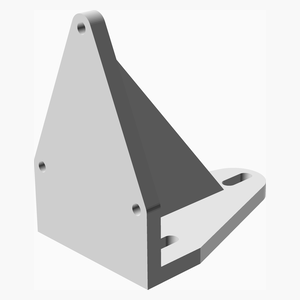
| 3 | Screw M3 cap x 8mm |
| 3 | Screw No8 pan wood x 30mm |
| 3 | Washer M3 x 7mm x 0.5mm |
| 3 | Washer M5 x 10mm x 1mm |
| 1 x bracket.stl |
|---|
 |
| 1 x motor_assembly |
|---|
 |
[blocked]
| Qty | Description |
|---|---|
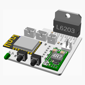
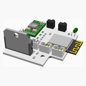
| 1 | ESP-12F ESP8266 WiFi module |
| 1 | JST PH connector 2 way |
| 2 | JST PH connector 3 way |
| 1 | LED 3 mm green |
| 1 | MULTIWATT11 L6203 |
| 1 | Molex KK header 2 way |
| 1 | Molex KK housing 2 way |
| 1 | PCB Blinder |
| 2 | SMD capacitor 0805 100n |
| 2 | SMD capacitor 0805 15n |
| 1 | SMD capacitor 0805 220n |
| 5 | SMD resistor 0805 10K 0.125W |
| 2 | SMD resistor 0805 1K 0.125W |
| 1 | SMD resistor 0805 2K2 0.125W |
| 2 | Square button 6mm |
| 1 | Ultra Small 3A buck regulator |
[blocked]
| Qty | Description |
|---|---|
| 1 | Nut M3 x 2.4mm nyloc |
| 1 | Screw M3 cs cap x 12mm |
| 1 | Washer M3 x 7mm x 0.5mm |
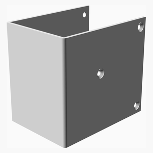
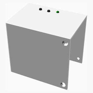
| 1 x cover.stl |
|---|
 |
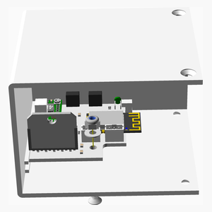
| 1 x blinder_PCB_assembly |
|---|
|
[blocked]
| Qty | Description |
|---|---|
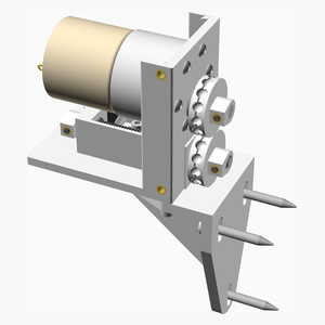
| 4 | Screw M3 cs cap x 5mm |
| 1 x bracket_assembly | 1 x cover_assembly |
|---|---|
 | |
| Qty | Value | Footprint | References |
|---|---|---|---|
| 5 | 10K | Resistor_SMD:R_0805_2012Metric_Pad1.20x1.40mm_HandSolder | R1, R2, R3, R4, R5 |
| 2 | 100n | Capacitor_SMD:C_0805_2012Metric_Pad1.18x1.45mm_HandSolder | C1, C3 |
| 2 | 15n | Capacitor_SMD:C_0805_2012Metric_Pad1.18x1.45mm_HandSolder | C4, C5 |
| 2 | 1K | Resistor_SMD:R_0805_2012Metric_Pad1.20x1.40mm_HandSolder | R7, R8 |
| 1 | 220n | Capacitor_SMD:C_0805_2012Metric_Pad1.18x1.45mm_HandSolder | C2 |
| 1 | 2K2 | Resistor_SMD:R_0805_2012Metric_Pad1.20x1.40mm_HandSolder | R6 |
| 1 | 3.3V | NopHead:TinyBuck | U1 |
| 1 | DOWN | Button_Switch_THT:SW_Tactile_SPST_Angled_PTS645Vx39-2LFS | SW2 |
| 1 | DOWN LIMIT | Connector_JST:JST_PH_B3B-PH-K_1x03_P2.00mm_Vertical | J3 |
| 1 | ESP-12F | RF_Module:ESP-12E | U2 |
| 1 | L6203 | L6203:MULTIWATT-11 | IC1 |
| 1 | MOT | Connector_JST:JST_PH_B2B-PH-K_1x02_P2.00mm_Vertical | J5 |
| 1 | PGM | Connector_PinHeader_2.54mm:PinHeader_1x06_P2.54mm_Vertical | J2 |
| 1 | PWR | Connector_Molex:Molex_KK-254_AE-6410-02A_1x02_P2.54mm_Vertical | J1 |
| 1 | UP | Button_Switch_THT:SW_Tactile_SPST_Angled_PTS645Vx39-2LFS | SW1 |
| 1 | UP LIMIT | Connector_JST:JST_PH_B3B-PH-K_1x03_P2.00mm_Vertical | J4 |
| 1 | green | LED_THT:LED_D3.0mm_Horizontal_O1.27mm_Z2.0mm | D1 |
The 24 most common of 25 parts.
It measures 42 × 45 mm and has 4 copper layers, 1.6 mm thick.
25 parts, built around the ESP-12F and L6203. The full list of its parts is on this page, with links to each part's symbol and footprint where PCBKit's library has them.
From the nophead/Blinder repository on GitHub, at the commit this page was made from: the board is PCB/Blinder/Blinder.kicad_pcb and its schematic PCB/Blinder/Blinder.kicad_sch. PCBKit opens the board in the browser, with nothing to install.
Its repository publishes it under the GPL-3.0 licence: you may reuse it on that licence's terms (keep the author's notice, and for a copyleft licence share your changes alike).


trublion/turtable_control_board_hbridge
HW control board for turntable. Controls a DC motor with a H-bridge, reads an analog audio signal envelope, dual-PCB design.

h07jonas/SYNCHRO
SYNCHRO System for Yielding Networked CHannel Rail Operation SYNCHRO is a modular, high-performance digital model railroad control ecosystem architecture based on the DCC (Digital Command Control) standard.


Staacks/there.oughta.be
Projects featured on my blog at https://there.oughta.be