Skip to the content
2 layers148.8 × 54.6 mmBowen nixie device, the printed circuit board in 3D

The hardware is designed in KiCad and all design files are included in the hardware directory. The hardware consists of the design of the main board PCB and three different versions of the PL31 socket breakout boards.

Size
148.8 × 54.6 mm
Copper layers
2
Thickness
1.6 mm
Parts
121
Nets
159
Pads
446
Tracks, vias
665, 106
Pours
1
Routed
Yes
KiCad
KiCad 10.0 (file 20260206)
Created
7 Apr 2023
Updated
12 Oct 2026

Overview

Bowen nixie device is an open-source printed circuit board by nonik0, from the nonik0/stemmett-nixie-device repository on GitHub. It is a 2-layer board of 148.8 × 54.6 mm with 121 parts on 159 nets, routed with 665 tracks and 106 vias.

It is built around the 74HC595, MMBTA42 and MMBTA92. Its parts include 52 resistors, 48 transistors, 7 ICs and 5 connectors. It belongs with the lEDs and displays boards and the ESP32 and RISC-V boards of this library.

Main components

3

README

README.md

Stemmett Nixie Device

Description

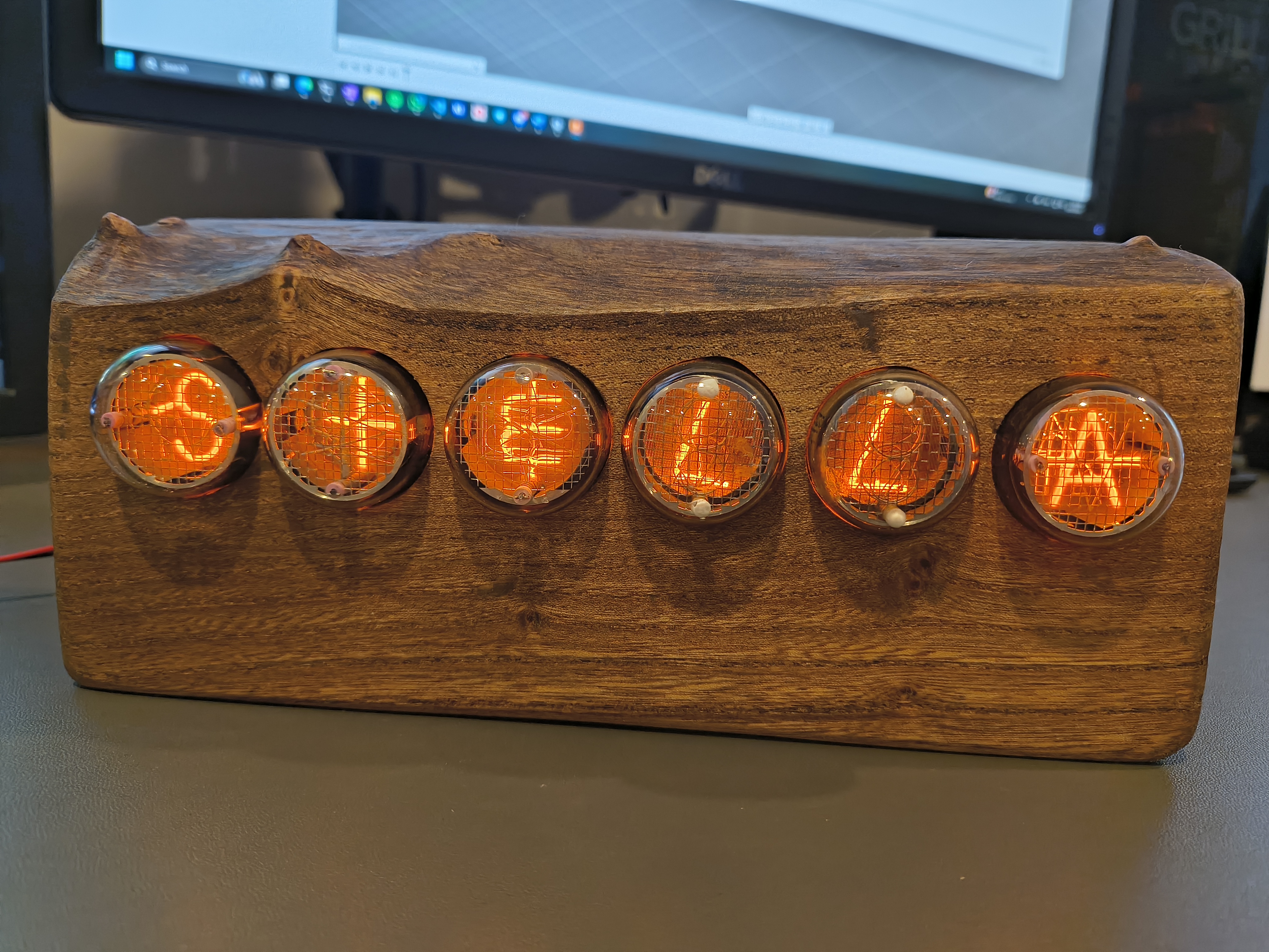
A Nixie device that uses front-viewed PL31 socket Nixie tubes (IN-4, IN-7, IN-7A, IN-7B) in different orientations to create makeshift letters and spell things like names! The main board itself has 6 sockets for custom PL31 breakout boards, which have the nixie tube sockets in different orientations to rotate the Nixie tubes. By rotating the tubes we can pseudo-spell things, see images below for example (i.e. "7" rotated 180° to be an "L", or "m" rotated -90° to be a small-sized "E").

The hardware is designed in KiCad and all design files are included in the hardware directory. The hardware consists of the design of the main board PCB and three different versions of the PL31 socket breakout boards. The overall component choices target using simple through-hole components so the PCB is easier to debug, as it is my first PCB design. All cathodes of the nixie tubes are controlled with a single pin with serial, using three 74HC595 shift registers to control the input of the six old school К155ИД1 (K155ID1, SN74141) driver chips for each nixie tube. Each tube anode has a simple MOSFET circuit to be able to PWM each tube individually, allowing each tube to be individually dimmed or turned off. I am using the tiny awesome NCH8200HV for the high voltage supply.

The firmware is a PlatformIO-based project targetting the TinyS3 ESP32 dev board. All source files are included in the firmware directory. The firmware will cycle through various different animations, returning to the configured name/word between each. It has a basic HTTP UX with REST interface to update settings--enable/disable animations, changing brightness, etc. It is simple to customize the firmware to any tube configuration by creating a new one in board.h.

Bowen Nixie Device

See the Bowen Nixie Device README.

Images

PCB Layout and Bare PCBs
circuitboard photoof2devices
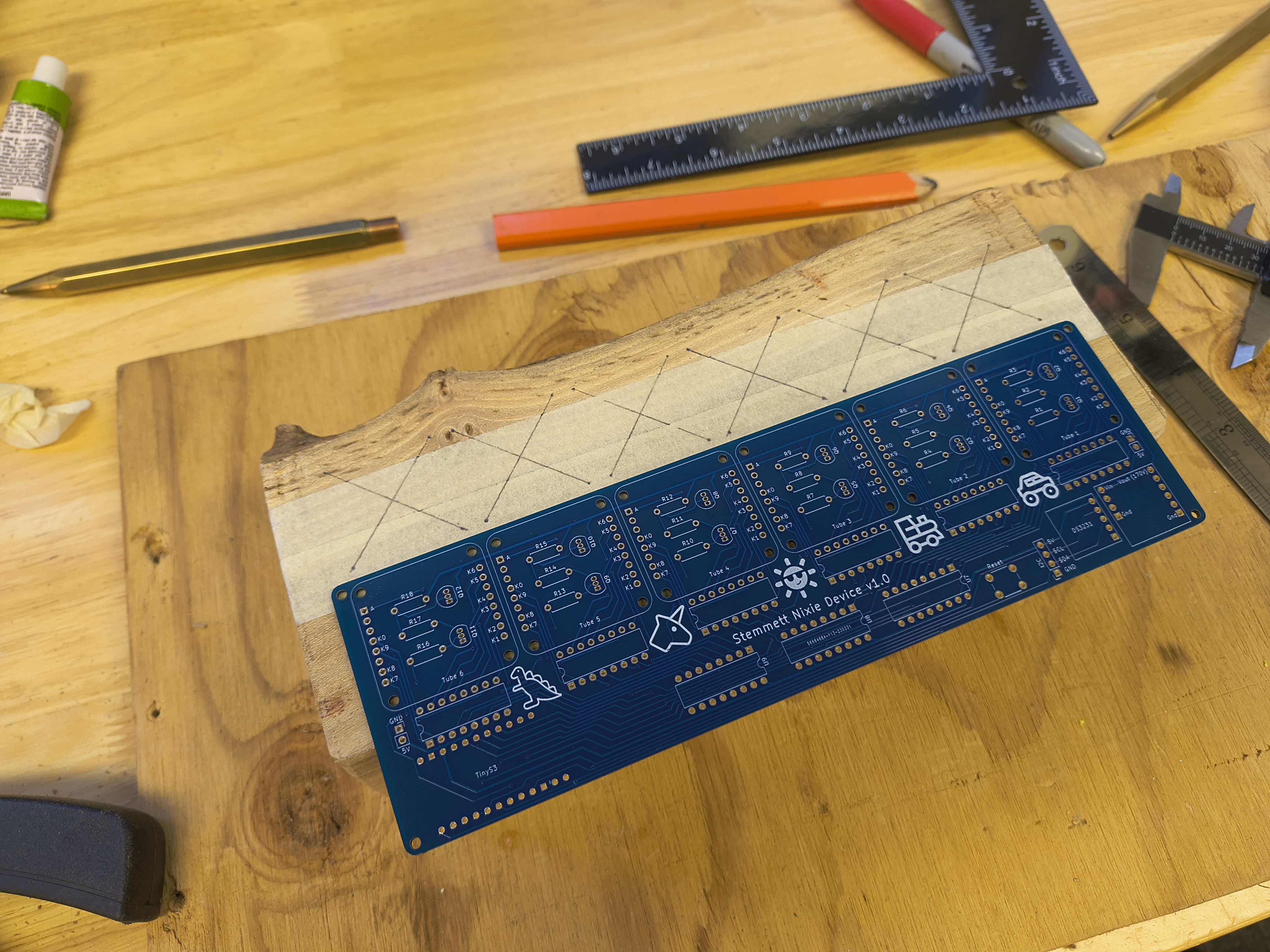
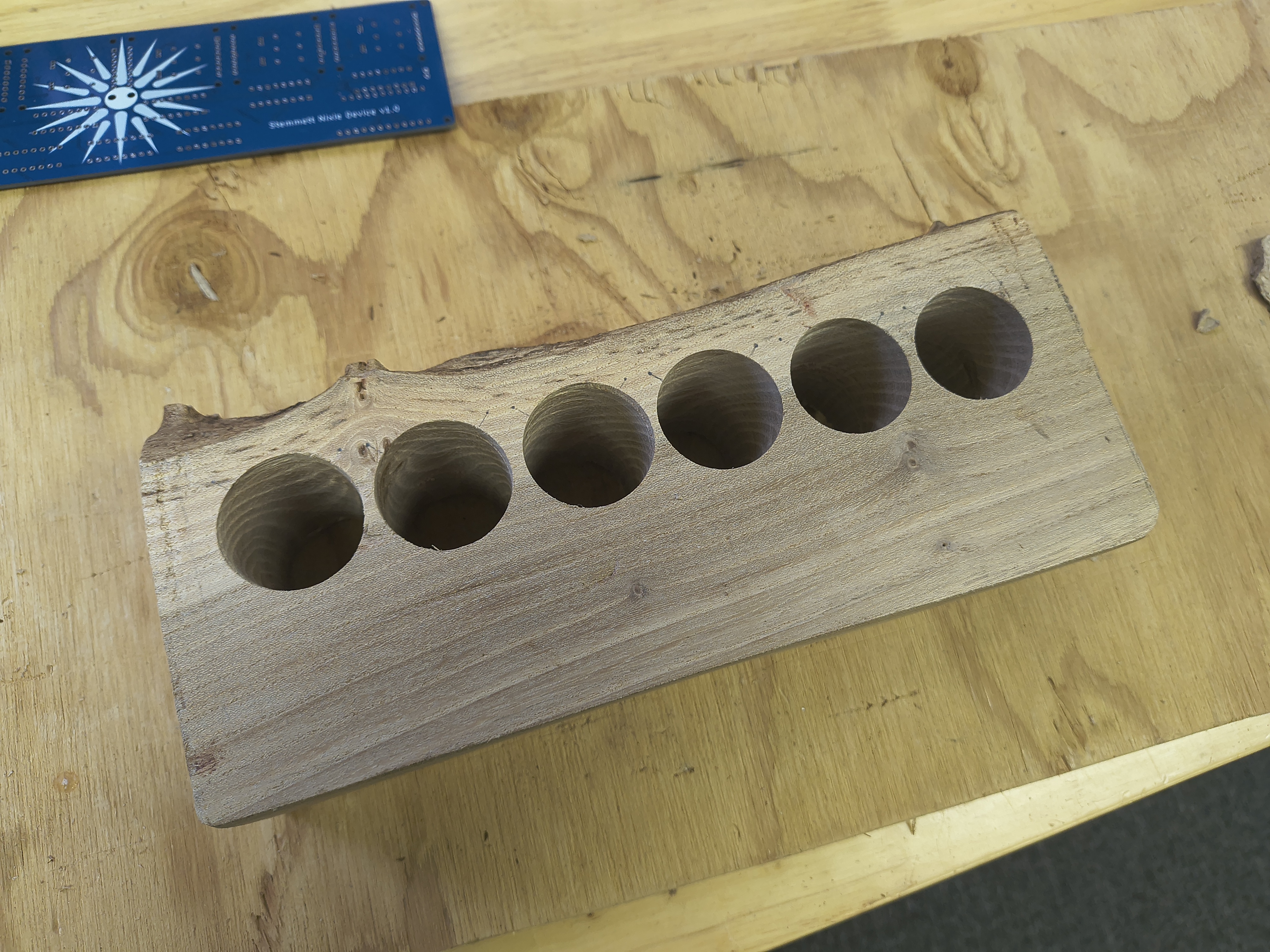
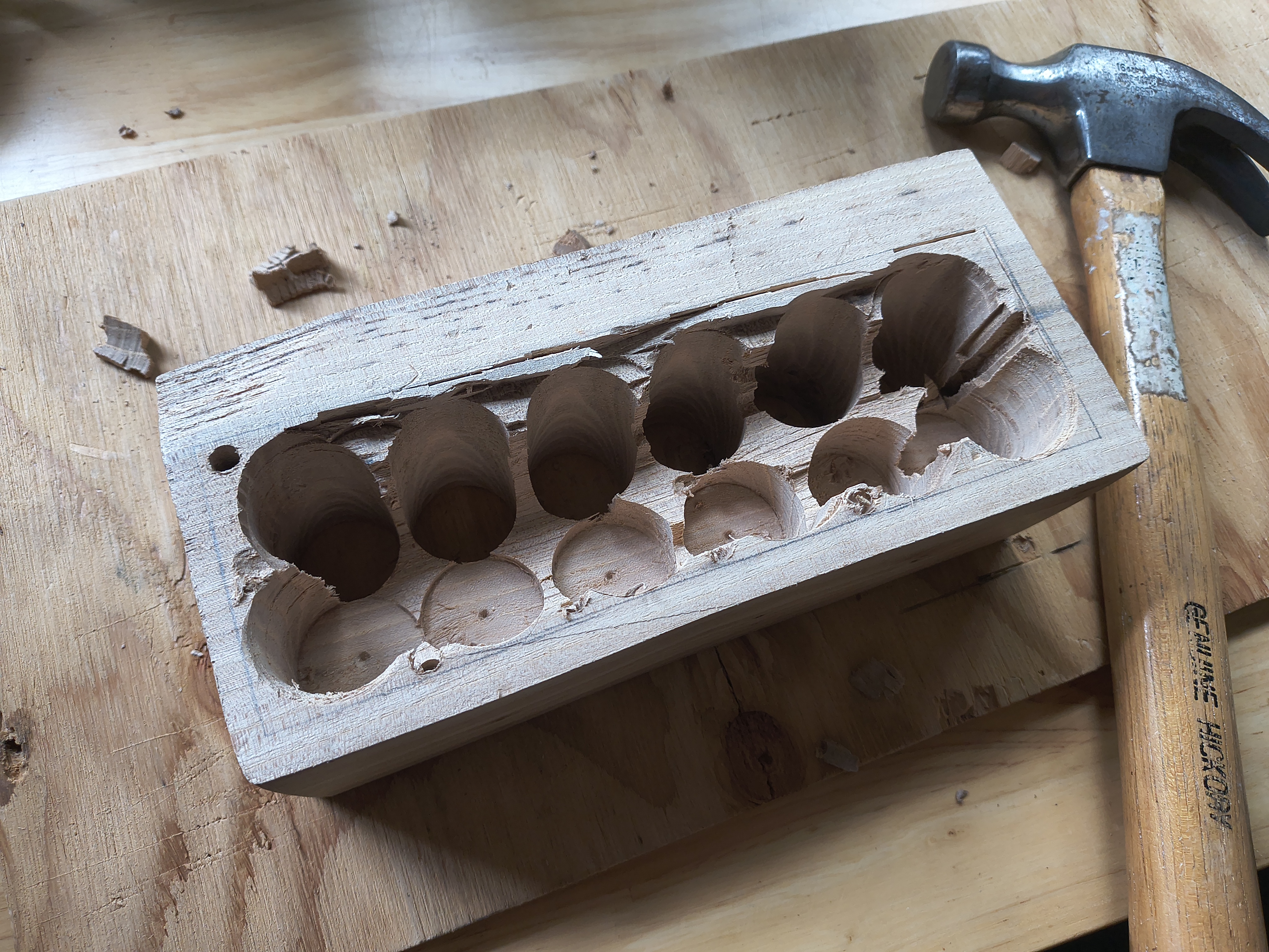
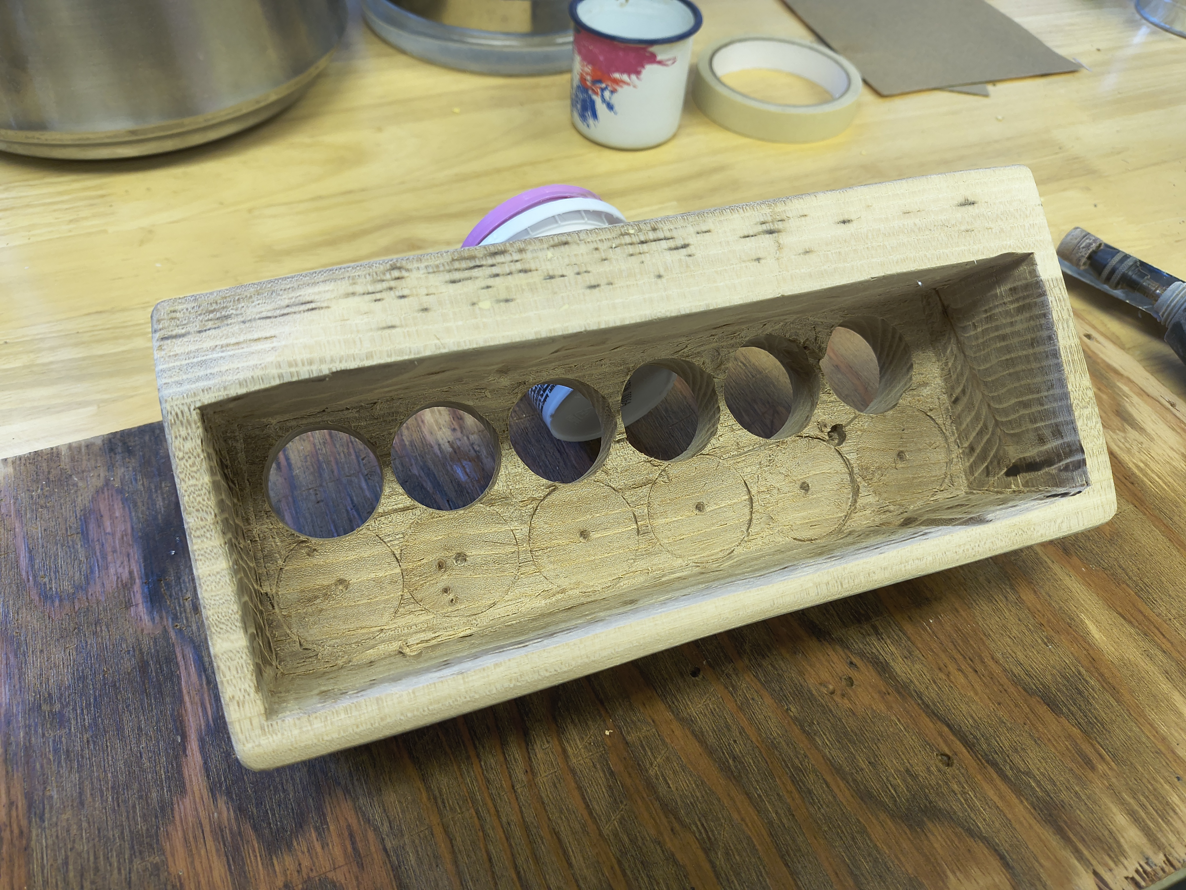
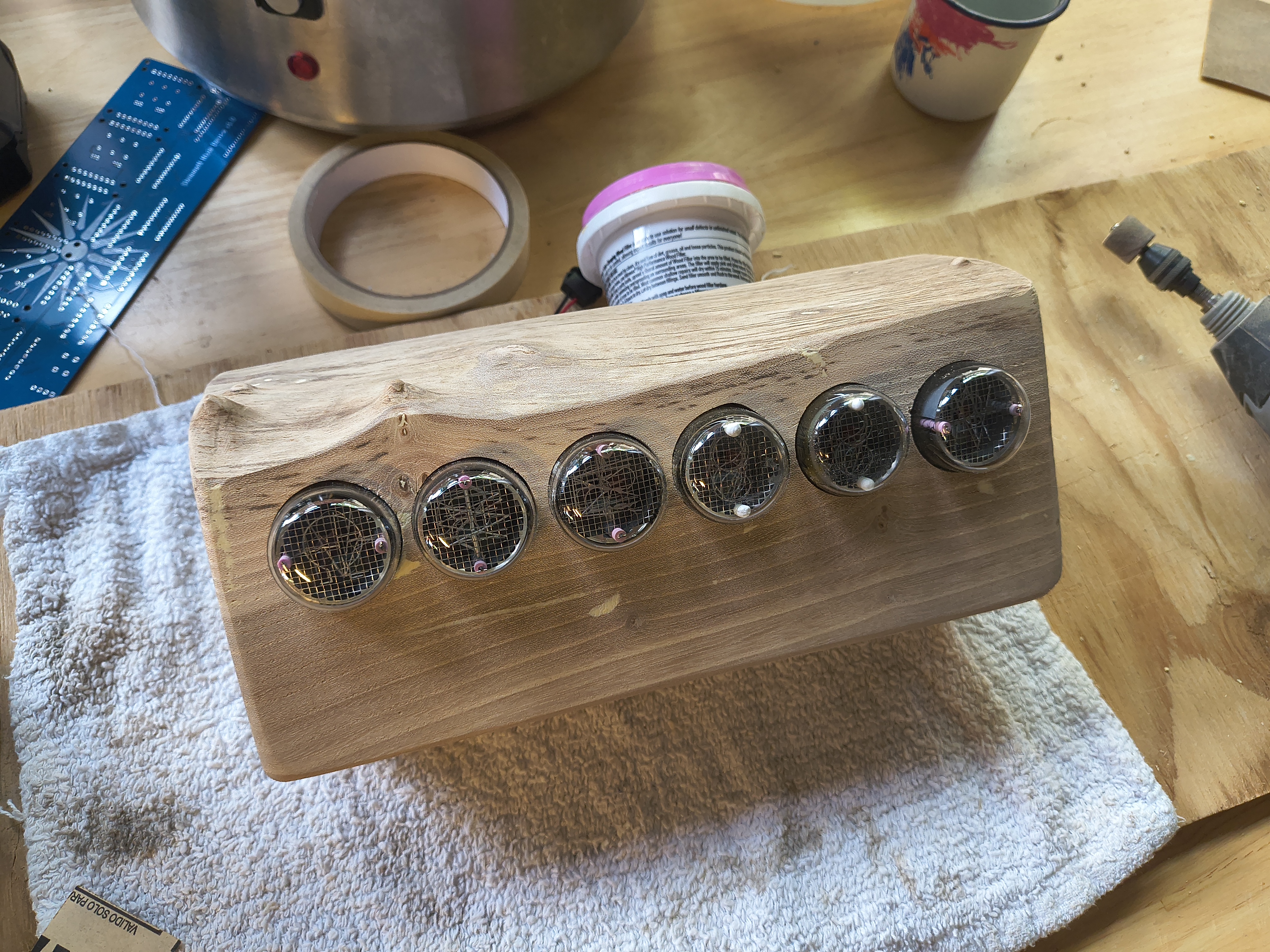
Wood Block to Enclosure

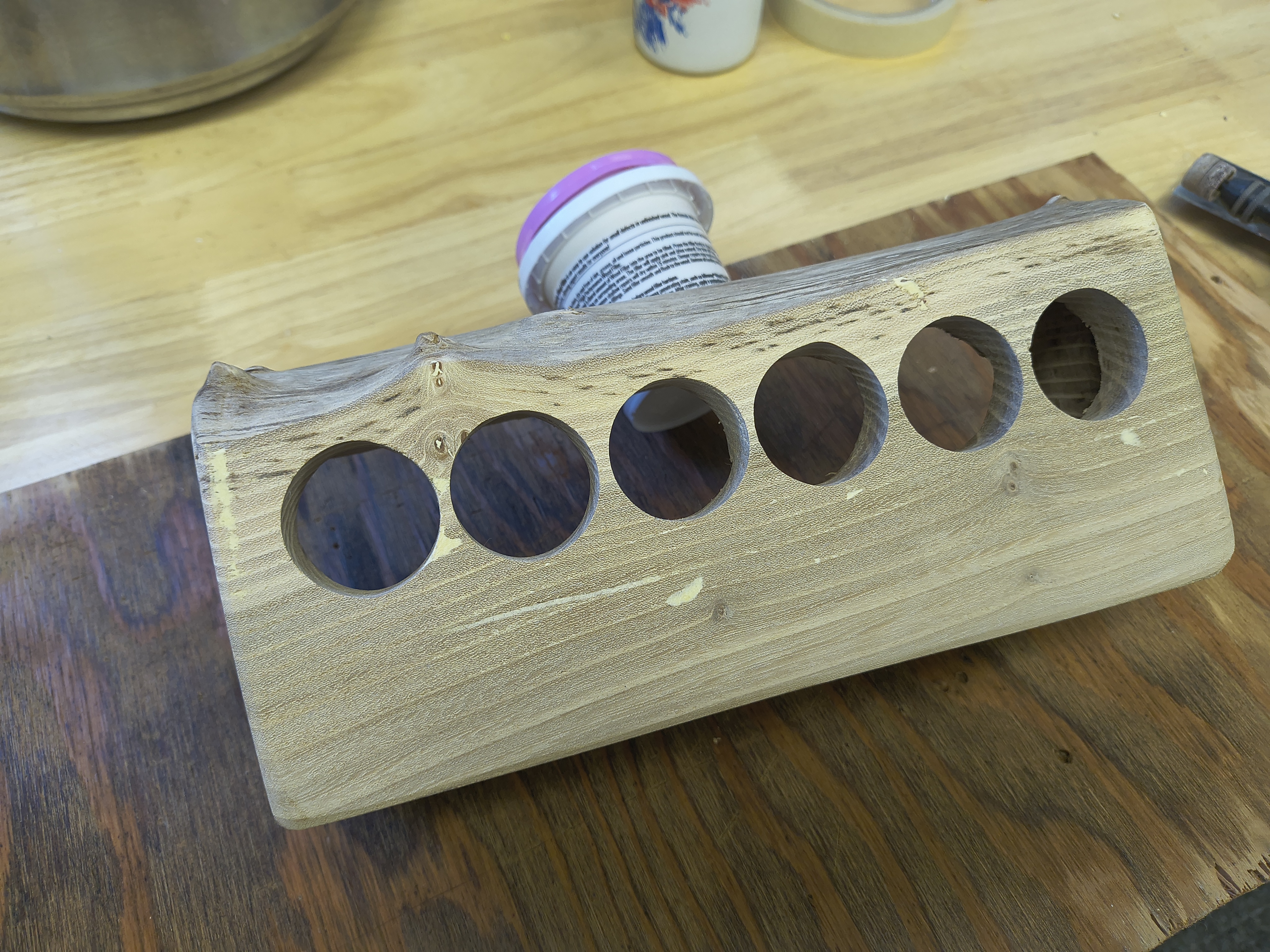
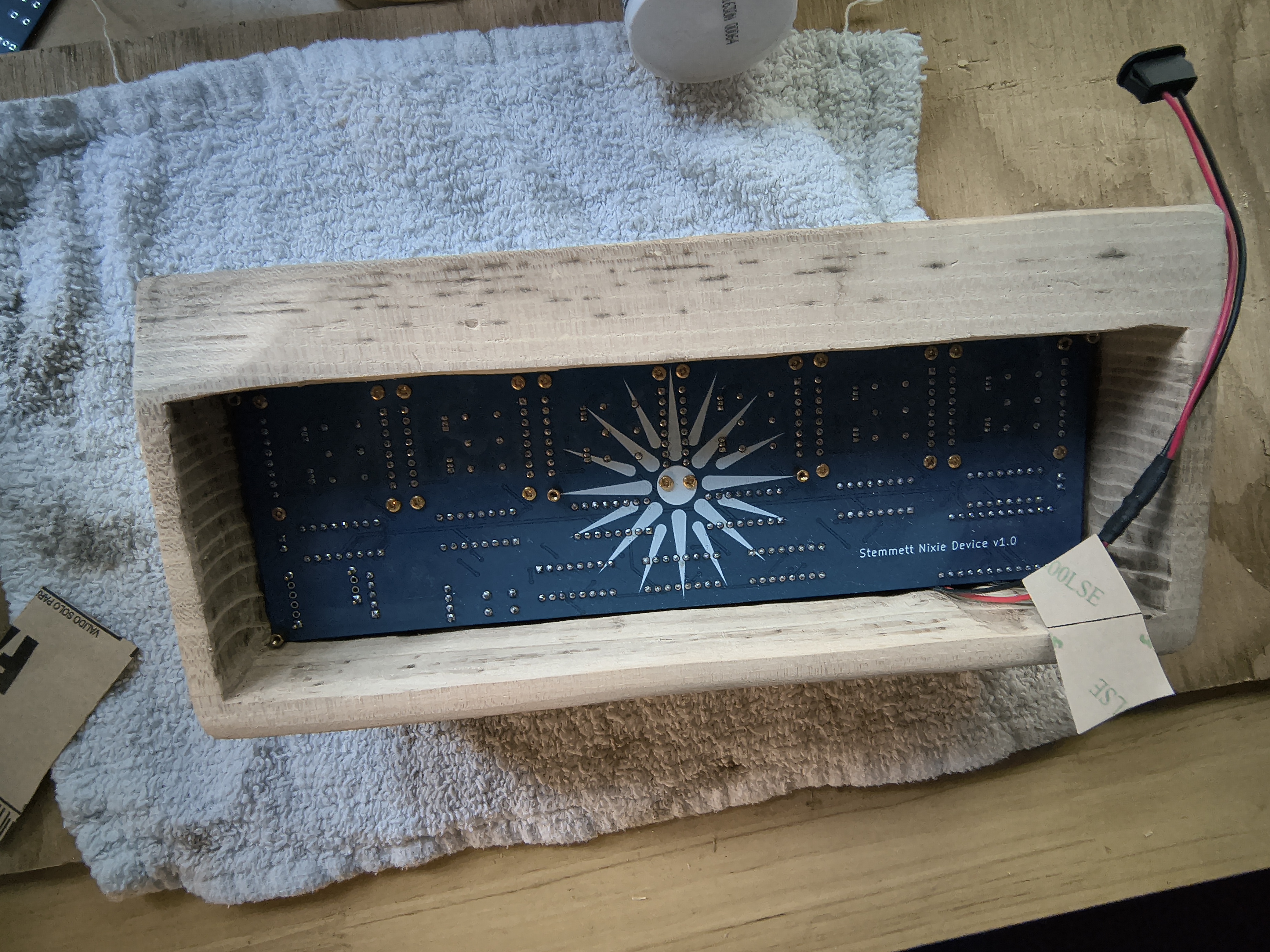
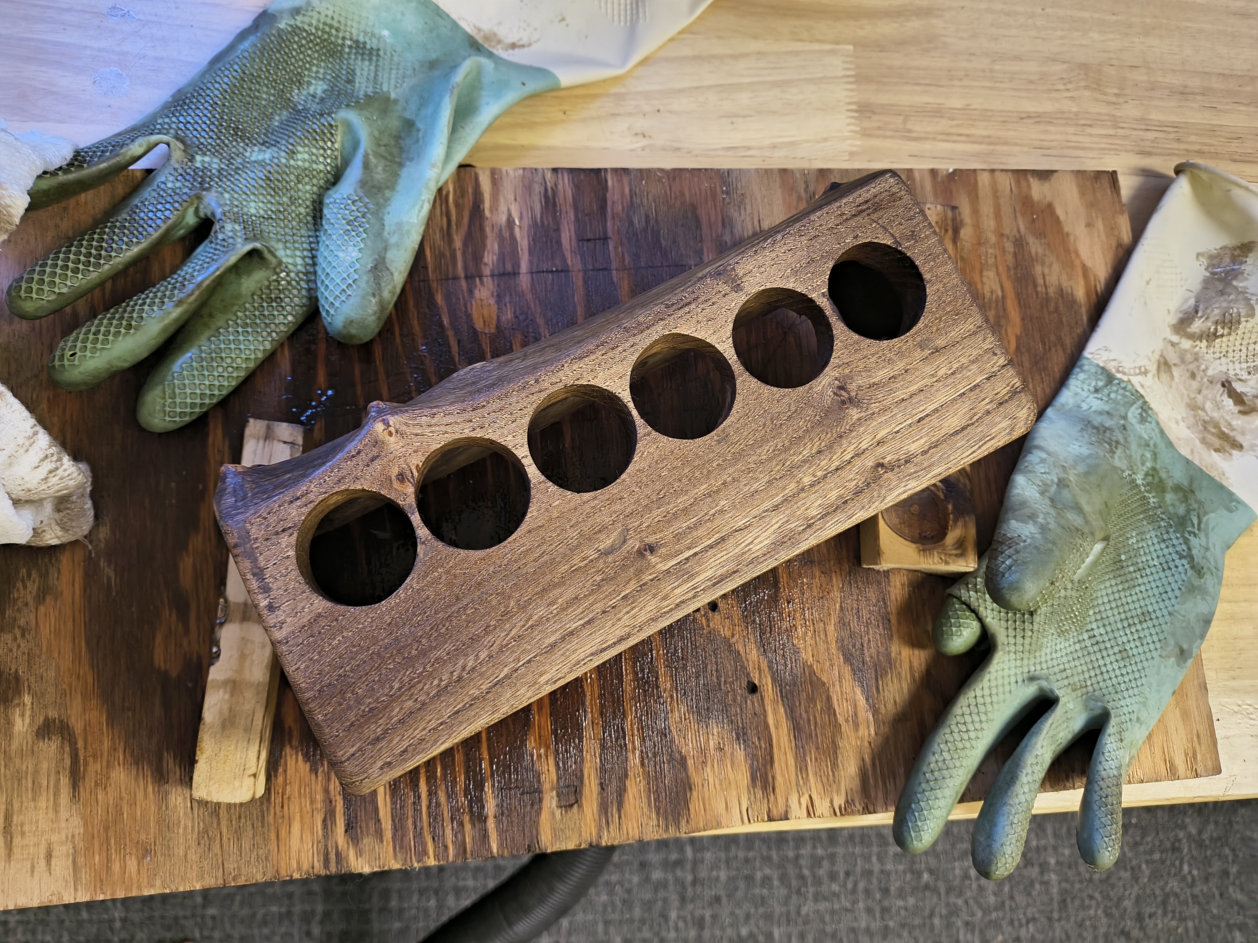
Fitting and Finishing
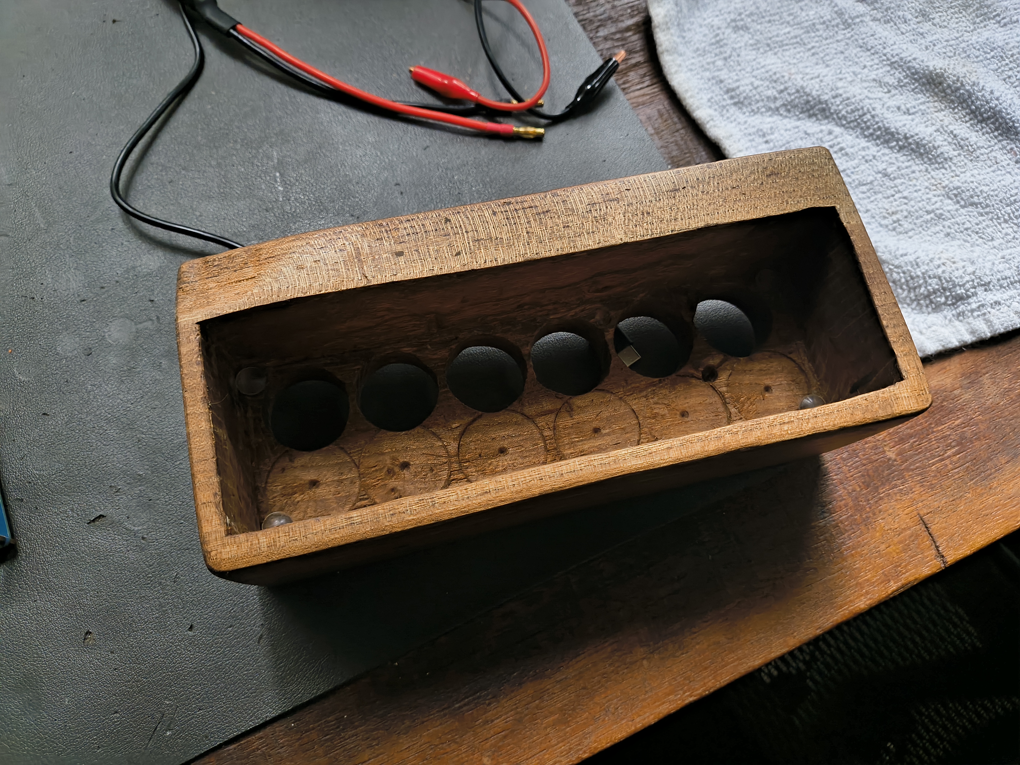
Finished Enclosure
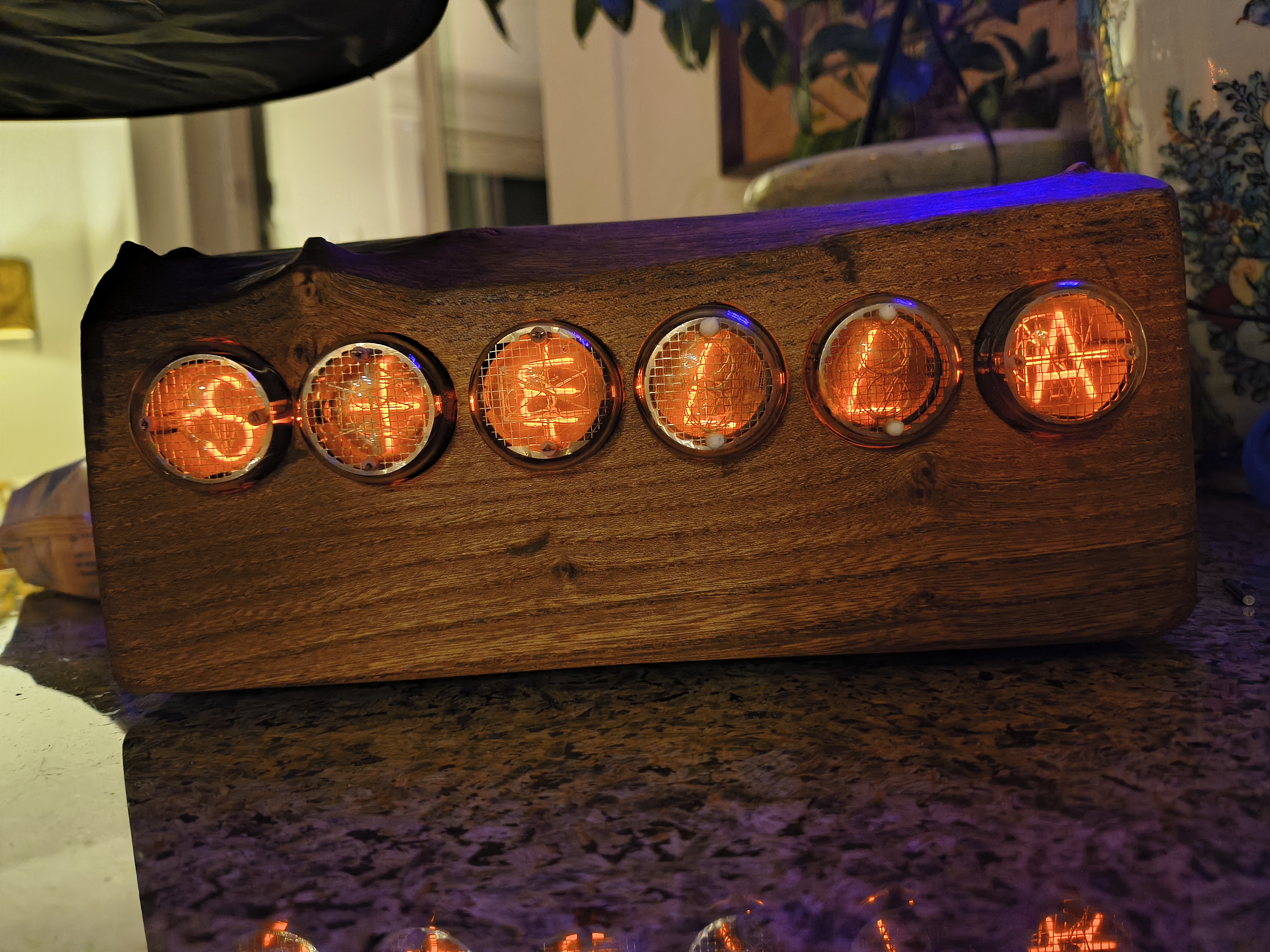
Alternate Enclosure
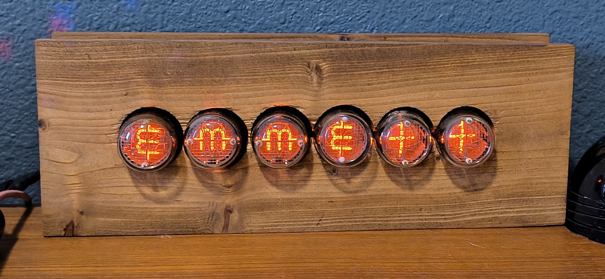
Animations

Glitch Animation Random Scan Animation

TODO: animations in better lighting...

Parts

121
QtyValueFootprintReferences
4410kResistor_SMD:R_0603_1608MetricR1, R10, R13, R14, R15, R16, R17, R18, R19, R20, R21, R22, R23, R24, R25, R26 +28
44MMBTA42Package_TO_SOT_SMD:SOT-23Q1, Q10, Q11, Q12, Q13, Q14, Q15, Q16, Q17, Q18, Q19, Q20, Q21, Q22, Q23, Q24 +28
574HC595Package_SO:SOIC-16_4.55x10.3mm_P1.27mmU2, U3, U4, U5, U6
5MountingHoleMountingHole:MountingHole_2.2mm_M2_DIN965_PadH1, H2, H3, H4, H5
4100kResistor_SMD:R_0603_1608MetricR3, R6, R9, R12
4470kResistor_SMD:R_1206_3216MetricR2, R5, R8, R11
4MMBTA92PCM_Package_TO_SOT_SMD_AKL:SOT-23Q2, Q4, Q6, Q8
4~Nixie:PL31 Socket BreakoutT1, T2, T3, T4
2Conn_01x02_PinConnector_PinSocket_2.54mm:PinSocket_1x02_P2.54mm_VerticalJ1, J2
1Conn_01x03_PinConnector_PinSocket_2.54mm:PinSocket_1x03_P2.54mm_VerticalJ5
1Conn_01x04_PinConnector_PinSocket_2.54mm:PinSocket_1x04_P2.54mm_VerticalJ3
1MOUDLE-SEEEDUINO-XIAO-ESP32C3Nixie:XIAO-ESP32-C3-DIPU1
1NCH8200HVNixie:NCH8200HVU11
1Qwiic/Stemma QTPCM_SparkFun-Connector:JST_1x04_P1.0mm_Vertical_SMDJ4

More from nonik0/stemmett-nixie-device

3
  • 2 layers205.5 × 63.5 mmStemmett nixie device, the printed circuit board in 3D

    Stemmett nixie device

    nonik0/stemmett-nixie-device

    The hardware is designed in KiCad and all design files are included in the hardware directory. The hardware consists of the design of the main board PCB and three different versions of the PL31 socket breakout boards.

    62 parts4
  • 2 layers31.8 × 31.8 mmIN4-0D socket, the printed circuit board in 3D

    IN4-0D socket

    nonik0/stemmett-nixie-device

    The hardware is designed in KiCad and all design files are included in the hardware directory. The hardware consists of the design of the main board PCB and three different versions of the PL31 socket breakout boards.

    5 parts4
  • 2 layers31.8 × 31.8 mmIN7-0D socket, the printed circuit board in 3D

    IN7-0D socket

    nonik0/stemmett-nixie-device

    The hardware is designed in KiCad and all design files are included in the hardware directory. The hardware consists of the design of the main board PCB and three different versions of the PL31 socket breakout boards.

    5 parts4

Similar boards

  • 2 layers213 × 54 mmNixie board, the printed circuit board in 3D

    Nixie board

    Hardware7253/OperationUrd

    A nixie tube clock inspired by the divergence meter from Steins;Gate.

    99 parts1MIT
  • 4 layers128 × 60 mmNixiClockV1, the printed circuit board in 3D

    NixiClockV1

    zOnlyKroks/pcb-consortium

    117 partsCC0-1.0
  • 2 layers85 × 56.5 mmModemHAT, the printed circuit board in 3D

    ModemHAT

    astuder/ModemHAT

    Classic Phone Modem HAT for the Raspberry Pi

    111 parts56
  • 2 layers137.2 × 30.5 mmPanaplex, the printed circuit board in 3D

    Panaplex

    74hc595/Panaplex-Clock

    Code/schematics for a clock using a Panaplex (planar gas discharge) display

    30 parts12BSD-3-Clause
  • 2 layers100 × 100 mmSynchroDriverD, the printed circuit board in 3D

    SynchroDriverD

    schlae/SynchroDriver

    Various boards for driving synchros and other 400Hz devices

    252 parts1
  • 4 layers86 × 47 mmSmd board, the printed circuit board in 3D

    Smd board

    hinatadayo/nixie-token-display

    115 parts
  • 2 layers50.2 × 19.4 mmHead3, the printed circuit board in 3D

    Head3

    kntzn/head

    77 parts
  • 4 layers90 × 95 mmBldc48, the printed circuit board in 3D

    Bldc48

    kobertkirk/bldc

    A KiCad hardware design plus STM32 firmware for a hall-sensored e-bike or scooter hub motor:

    133 parts

Questions

How big is the Bowen nixie device PCB?

It measures 148.8 × 54.6 mm and has 2 copper layers, 1.6 mm thick.

What parts does the Bowen nixie device use?

121 parts, built around the 74HC595, MMBTA42 and MMBTA92. The full list of its parts is on this page, with links to each part's symbol and footprint where PCBKit's library has them.

Where can I download the Bowen nixie device KiCad files?

From the nonik0/stemmett-nixie-device repository on GitHub, at the commit this page was made from: the board is hardware/kicad/bowen-nixie-device/bowen-nixie-device.kicad_pcb and its schematic hardware/kicad/IN4-0D-socket/IN4-0D-socket.kicad_sch. PCBKit opens the board in the browser, with nothing to install.

Can I use the Bowen nixie device design in my own project?

Its repository states no licence, so its author keeps all rights: ask nonik0 before reusing the design.