
2 layers15 × 14.2 mm
Stlink clone adapter
noahp/stlink-clone-adapter
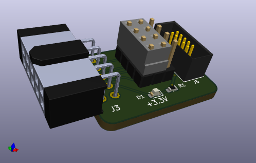
2x5 0.1" header to arm cortex 10-pin header adapter
2 parts2

 noahp/stlink-clone-adapter2
2x5 0.1" header to arm cortex 10-pin header adapter
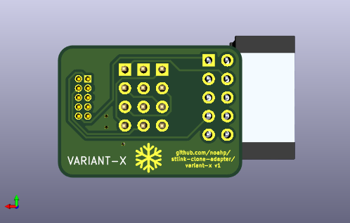
Stlink clone adapter is an open-source printed circuit board by noahp, from the noahp/stlink-clone-adapter repository on GitHub. It is a 2-layer board of 25.1 × 18 mm with 9 parts on 16 nets, routed with 76 tracks and 3 vias.
Its parts include 5 connectors, 1 resistor and 1 diode. It belongs with the interfaces and adapters boards of this library.
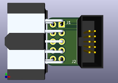
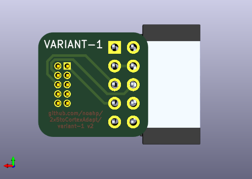
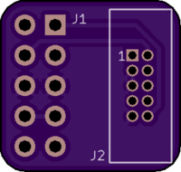
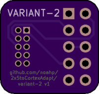
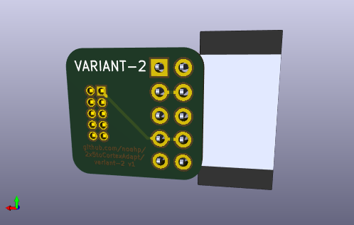
Adapter board for a 2x5 0.1" (2.54mm) header to arm cortex 10-pin connector.
This is useful when connecting ST-Link v2 clones to a standard ARM 2x5 1.27mm pitch header.
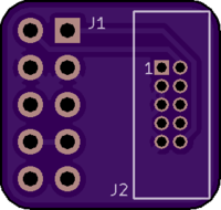
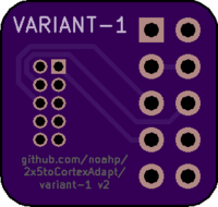
I know of 2 variants of the ST-Link v2 clones, with different pinouts on the 2x5 0.1" (2.54mm) header. Different adapter boards provided for each variant.
One way to distinguish the variants; when unplugged, check for continuity on pins 3+4 or 5+6.
Older model I bought in ~2016.
From the pin 1 marker on the header on the ST-Link, pinout is as follows:
| Funtion | Pin | Pin | Function |
|---|---|---|---|
| RST* | 1 | 2 | SWDIO |
| GND* | 3 | 4 | GND |
| SWIM | 5 | 6 | SWCLK |
| 3.3V | 7 | 8 | 3.3V |
| 5.0V | 9 | 10 | 5.0V |
*Note that the labeling is incorrect for some pins on the etching on the case / on the silkscreen on the board. My device had the pinout for Variant-2 on the etching and just incorrect on the silkscreen markings 🤷.
Newer model I bought in 2020.
From the pin 1 marker on the header on the ST-Link, pinout is as follows:
| Funtion | Pin | Pin | Function |
|---|---|---|---|
| RST | 1 | 2 | SWCLK |
| SWIW | 3 | 4 | SWDIO |
| GND | 5 | 6 | GND |
| 3.3V | 7 | 8 | 3.3V |
| 5.0V | 9 | 10 | 5.0V |
Labeling appears to be correct on these devices.
UNTESTED DESIGN
Support both pinouts with a 3x4 0.1" header to select between them.
Alternative approaches:
Quick note about using the stlink v2 clones with pyocd; I had the best luck using the device after updating the firmware using the official ST updater:
❯ java -jar stsw-link007/AllPlatforms/STLinkUpgrade.jar -jtag_swim -force_prog
Firmware version detected: V2J29S7
................Upgrade is successful.
Version read: 2.37.7
After upating the version should report V2J37S7 if you run the updater again.
There's a ton of information out there on the stlink devices themselves (I found this helpful).
On ubuntu there's an available package stlink-tools (source) which contains some utilities and udev rules for the st-link devices. I didn't end up using the tools themselves but it could come in handy.
| Qty | Value | Footprint | References |
|---|---|---|---|
| 3 | Conn_01x04 | project-lib:PinHeader_1x04_P2.54mm_Vertical | J1, J2, J4 |
| 1 | 1K | Resistor_SMD:R_0603_1608Metric | R1 |
| 1 | Conn_02x05_Odd_Even | Connector_PinSocket_2.54mm:PinSocket_2x05_P2.54mm_Horizontal | J3 |
| 1 | Conn_ARM_JTAG_SWD_10 | kicadlib:ARM_10_PIN | J5 |
| 1 | LED | LED_SMD:LED_0603_1608Metric | D1 |
The 7 most common of 9 parts.
noahp/stlink-clone-adapter
2x5 0.1" header to arm cortex 10-pin header adapter

noahp/stlink-clone-adapter
2x5 0.1" header to arm cortex 10-pin header adapter


FrameworkComputer/ExpansionCards
Reference designs and documentation to create Expansion Cards for the Framework Laptop

VoronDesign/Voron-Hardware
Cool Hardware designed by the Voron Design group

hackclub/OnBoard
💡 Join 1,000 teenagers and make your first PCB with a $100 grant!


adamws/kicad-kbplacer
KiCad plugin for automatic keyboard's key placement and routing
It measures 25.1 × 18 mm and has 2 copper layers, 1.6 mm thick.
9 parts. The full list of its parts is on this page, with links to each part's symbol and footprint where PCBKit's library has them.
From the noahp/stlink-clone-adapter repository on GitHub, at the commit this page was made from: the board is variant-x/stlink-clone-adapter.kicad_pcb. PCBKit opens the board in the browser, with nothing to install.
Its repository states no licence, so its author keeps all rights: ask noahp before reusing the design.