
4 layers16.9 × 119.4 mm

 noahp/samd11-breakout4
Little breakout for some spare samd11's.
Samd11-breakout is an open-source printed circuit board by noahp, from the noahp/samd11-breakout repository on GitHub. It is a 2-layer board of 34.4 × 20.4 mm with 17 parts on 31 nets, routed with 332 tracks and 21 vias.
It is built around the USBLC6-2SC6 and USB4105-GF-A. Its parts include 6 resistors, 4 connectors, 3 ICs, 2 capacitors and 2 diodes. It belongs with the interfaces and adapters boards and the SAM D and SAM boards of this library.



Little breakout for some spare samd11's.
Trying out https://debug-edge.io/ .
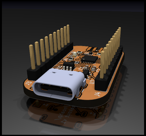
Octopart bom with bonus arm connector and flux:
.
├── Dockerfile  # tests run inside this
├── hw  # hardware design files
│   ├── fp-lib-table
│   ├── GCT_USB4105-GF-A.kicad_mod  # USB connector footprint
│   ├── samd11-breakout_3d_afterdark.png  # render
│   ├── samd11-breakout_3d.png  # render
│   ├── samd11-breakout-cache.lib
│   ├── samd11-breakout-ibom.html  # saved copy of interactive BOM
│   ├── samd11-breakout.kibot.yaml  # kibot config file
│   ├── samd11-breakout.kicad_pcb
│   ├── samd11-breakout.pdf  # schematic PDF
│   ├── samd11-breakout.pro  # kicad project
│   ├── samd11-breakout.sch
│   ├── sym-lib-table
│   ├── thirdparty/  # some thirdpart libraries used for the hardware
│   ├── USB4105-GF-A.lib  # USB connector kicad lib
│   └── USB4105-GF-A.step  # USB connector 3d model
├── README.md
├── sw  # software
│   ├── samd11-breakout.atstart  # project file for https://start.atmel.com/
│   └── samd11-breakout.atzip   # unpacked example system downloaded from above
└── test.sh # test script; builds docker image and runs tests in the containerAt the moment I'm just using the preset application with USB CDC, downloaded and unpacked into the directory described above.
| Qty | Value | Footprint | References |
|---|---|---|---|
| 2 | 1uF | Capacitor_SMD:C_0603_1608Metric | C1, C2 |
| 2 | 5.1k | Resistor_SMD:R_0603_1608Metric | R2, R3 |
| 2 | Conn_01x10_Male | Connector_PinHeader_2.54mm:PinHeader_1x10_P2.54mm_Vertical | J3, J4 |
| 1 | 1M | Resistor_SMD:R_0603_1608Metric | R1 |
| 1 | 1k | Resistor_SMD:R_0603_1608Metric | R4 |
| 1 | 30k | Resistor_SMD:R_0603_1608Metric | R5 |
| 1 | 47k | Resistor_SMD:R_0603_1608Metric | R6 |
| 1 | D_Schottky | Diode_SMD:D_SOD-523 | D2 |
| 1 | DebugEdge_02x03 | DebugEdge:DebugEdge_2x03_Target | J2 |
| 1 | LED | LED_SMD:LED_0603_1608Metric | D1 |
| 1 | MCP1700-3302E_SOT23 | Package_TO_SOT_SMD:SOT-23 | U2 |
| 1 | SAMD11D14A-M | Package_DFN_QFN:QFN-24-1EP_4x4mm_P0.5mm_EP2.6x2.6mm | U3 |
| 1 | USB4105-GF-A | project:GCT_USB4105-GF-A | J1 |
| 1 | USBLC6-2SC6 | Package_TO_SOT_SMD:SOT-23-6 | U1 |
It measures 34.4 × 20.4 mm and has 2 copper layers, 1.6 mm thick.
17 parts, built around the USBLC6-2SC6 and USB4105-GF-A. The full list of its parts is on this page, with links to each part's symbol and footprint where PCBKit's library has them.
From the noahp/samd11-breakout repository on GitHub, at the commit this page was made from: the board is hw/samd11-breakout.kicad_pcb. PCBKit opens the board in the browser, with nothing to install.
Its repository states no licence, so its author keeps all rights: ask noahp before reusing the design.

Allegra42/ZEReader-KiCad
ZEReader is an open source hardware and software E-Book Reader platform. Originally developed as a bachelor's thesis in electrical engineering, the project now evolves as a hobby initiative dedicated to further develop…

fdiwth/tvc-drone
This repository contains the documentation, hardware designs, and source code for a Thrust Vector Control (TVC) drone.

bobberdolle1/SkySweep32
Open-source passive multi-band RF monitoring system | 855–925 MHz, 2.4 GHz, 5.8 GHz | Rev C first prototype


mbed-ce/mbed-ce-ci-shield-v2
New version of the Mbed OS CE CI Shield -- a shield containing a logic analyzer and components to test features like I2C, SPI, and PWM.

animesh-chouhan/open-telegraph
A pocket-size Morse key. One button, one RGB LED, an ESP32-S3, and a battery. Plug it in over USB-C or pair it over Bluetooth and it types Morse into any device as a standard keyboard. Fully open, down to the copper.

mlab-modules/BATDATUNIT01
Multiple parallel Li-ion 18650 battery cell module with BMS and data storage with MCU control.