2 layers60 × 30 mm
Controller
google/mozc-devices
Circuit diagrams and firmware source code for Gboard DIY keyboards
11 parts3kApache-2.0

 nirav1385/AC-to-DC-converter-PCB
i have created my frist pcb using KiCad-10, 1-layer AC to DC Converter PCB Design.
Ac to dc converter is an open-source printed circuit board by nirav1385, from the nirav1385/AC-to-DC-converter-PCB repository on GitHub. It is a 2-layer board with 11 parts on 5 nets, routed with 35 tracks and 0 vias.
Its parts include 5 diodes, 2 resistors and 1 capacitor.
A compact, through-hole 12V AC to DC converter PCB designed in KiCad 10.0. This project converts 12V AC input into smooth DC output using a full-bridge rectifier with filtering, and includes a power indicator LED.
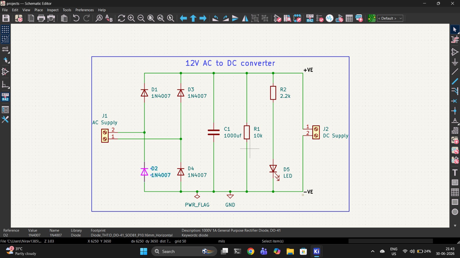
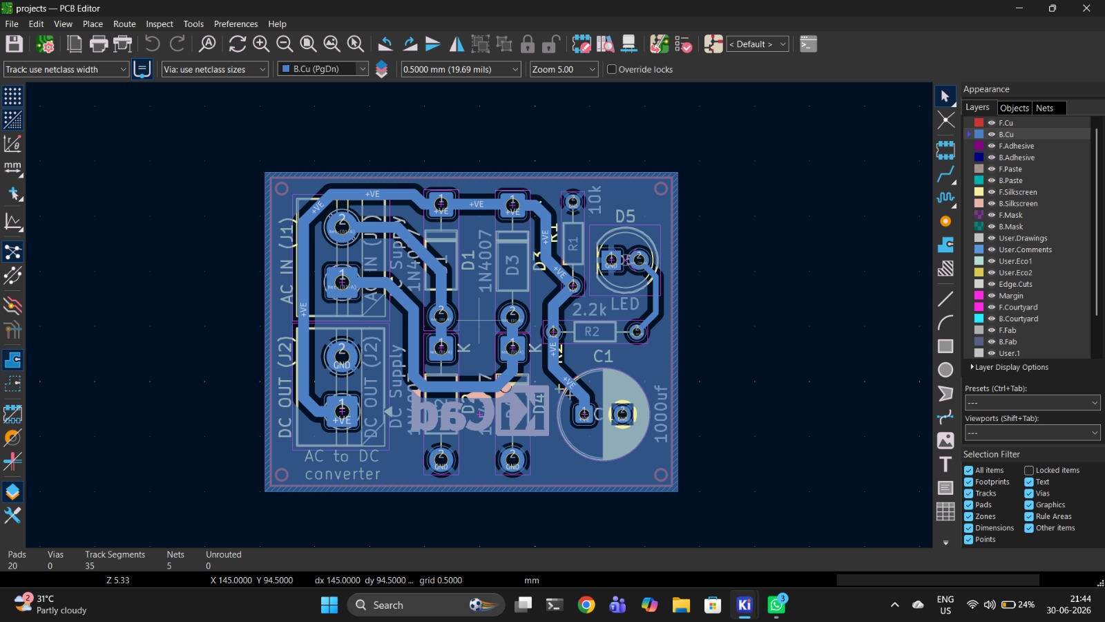
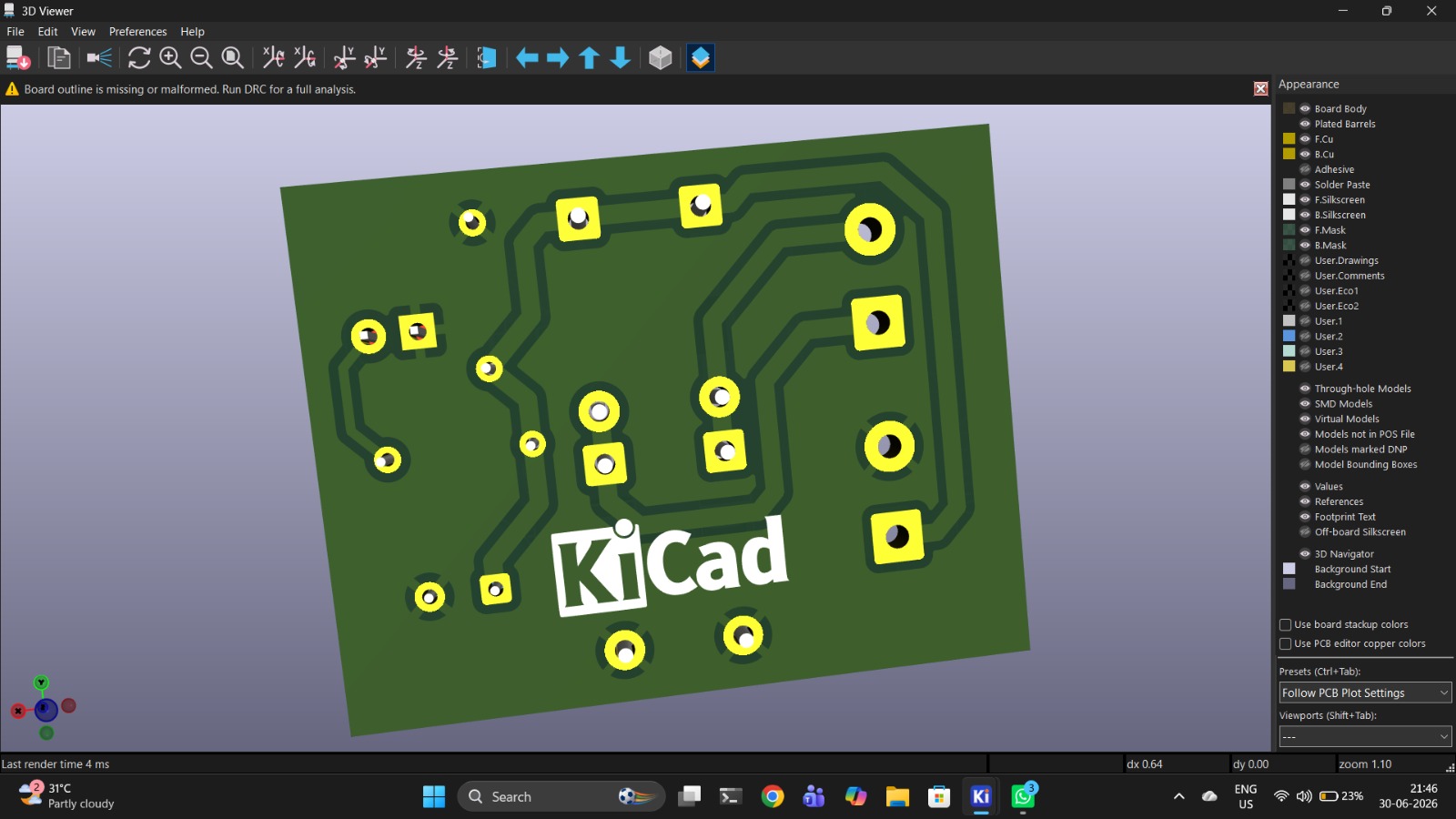
This is a classic unregulated AC to DC power supply circuit. It takes a 12V AC input (typically from a step-down transformer) and converts it to approximately ~15-17V DC (peak voltage minus diode drops) using a full-bridge rectifier.
The circuit consists of the following stages:
| Ref | Component | Value | Package/Footprint | Qty | Description |
|---|---|---|---|---|---|
| D1, D2, D3, D4 | 1N4007 | - | DO-41 (THT) | 4 | 1000V 1A General Purpose Rectifier Diode |
| D5 | LED | - | 5mm THT | 1 | Power Indicator LED |
| C1 | Electrolytic Capacitor | 1000µF | Radial D8.0mm P3.50mm | 1 | Filtering/Smoothing Capacitor |
| R1 | Resistor | 10kΩ | Axial DIN0204 (THT) | 1 | Bleeder/Discharge Resistor |
| R2 | Resistor | 2.2kΩ | Axial DIN0204 (THT) | 1 | LED Current-Limiting Resistor |
| J1 | Screw Terminal | 2-pin | MaiXu MX126 5.0mm pitch | 1 | AC Input Connector |
| J2 | Screw Terminal | 2-pin | MaiXu MX126 5.0mm pitch | 1 | DC Output Connector |
Total Components: 9
| Parameter | Details |
|---|---|
| EDA Tool | KiCad 10.0 |
| Layers | 1-layer (Front Copper) |
| Components | All Through-Hole (THT) |
| Connectors | Screw Terminals (5.0mm pitch) |
| Solder Mask | Both sides |
| Silkscreen | Both sides |
AC Input (12V AC)
      │
      ▼
┌──────────────┐
│   During positive half cycle:
│   Current flows: J1 Pin1 → D1 → +VE rail → Load → -VE rail → D4 → J1 Pin2
│
│   During negative half cycle:
│   Current flows: J1 Pin2 → D3 → +VE rail → Load → -VE rail → D2 → J1 Pin1
│
│   Result: Full-wave rectified pulsating DC
└──────────────┘
      │
      ▼
┌──────────────┐
│   C1 (1000µF) charges during voltage peaks and
│   discharges during valleys, smoothing the output
└──────────────┘
      │
      ▼
┌──────────────┐
│   R1 (10kΩ) provides a safe discharge path
│   R2 (2.2kΩ) + LED indicates power status
└──────────────┘V_out (peak) = V_ac(peak) - 2 × V_diode
= (12 × √2) - (2 × 0.7)
= 16.97 - 1.4
≈ 15.6V DC (peak)I_LED = (V_out - V_LED) / R2
= (15.6 - 2.0) / 2200
≈ 6.2 mA (safe operating current for LED)ac_to_dc_converter/
├── 📄 ac_to_dc_converter.kicad_pro # KiCad project file
├── 📄 ac_to_dc_converter.kicad_sch # Schematic file
├── 📄 ac_to_dc_converter.kicad_pcb # PCB layout file
├── 📁 Gerber/ # Manufacturing files (ready to fab)
│ ├── ac_to_dc_converter-F_Cu.gbr # Front copper layer
│ ├── ac_to_dc_converter-B_Cu.gbr # Back copper layer
│ ├── ac_to_dc_converter-F_Mask.gbr # Front solder mask
│ ├── ac_to_dc_converter-B_Mask.gbr # Back solder mask
│ ├── ac_to_dc_converter-F_Paste.gbr # Front paste layer
│ ├── ac_to_dc_converter-B_Paste.gbr # Back paste layer
│ ├── ac_to_dc_converter-F_Silkscreen.gbr# Front silkscreen
│ ├── ac_to_dc_converter-B_Silkscreen.gbr# Back silkscreen
│ ├── ac_to_dc_converter-Edge_Cuts.gbr # Board outline
│ ├── ac_to_dc_converter-PTH.drl # Plated through-holes drill
│ ├── ac_to_dc_converter-NPTH.drl # Non-plated through-holes drill
│ └── ac_to_dc_converter-job.gbrjob # Gerber job file
└── 📄 README.md # This fileac_to_dc_converter.kicad_proThe Gerber files are pre-generated and located in the Gerber/ folder. You can directly upload the Gerber folder (as a ZIP) to any PCB manufacturer:
Gerber/ folder into a .zip file⚡ CAUTION: This circuit deals with AC mains power (through a transformer). Always exercise proper safety precautions.
Nirav Jain — Designed with ❤️ using KiCad
This project is open-source. Feel free to use, modify, and distribute.
⭐ If you found this project helpful, please give it a star! ⭐
| Qty | Value | Footprint | References |
|---|---|---|---|
| 4 | 1N4007 | Diode_THT:D_DO-41_SOD81_P10.16mm_Horizontal | D1, D2, D3, D4 |
| 1 | 1000uf | Capacitor_THT:CP_Radial_D8.0mm_P3.50mm | C1 |
| 1 | 10k | Resistor_THT:R_Axial_DIN0204_L3.6mm_D1.6mm_P7.62mm_Horizontal | R1 |
| 1 | 2.2k | Resistor_THT:R_Axial_DIN0204_L3.6mm_D1.6mm_P7.62mm_Horizontal | R2 |
| 1 | AC Supply | TerminalBlock:TerminalBlock_MaiXu_MX126-5.0-02P_1x02_P5.00mm | AC IN (J1) |
| 1 | DC Supply | TerminalBlock:TerminalBlock_MaiXu_MX126-5.0-02P_1x02_P5.00mm | DC OUT (J2) |
| 1 | LED | LED_THT:LED_D5.0mm | D5 |
The 10 most common of 11 parts.
google/mozc-devices
Circuit diagrams and firmware source code for Gboard DIY keyboards


FrameworkComputer/ExpansionCards
Reference designs and documentation to create Expansion Cards for the Framework Laptop

hoglet67/RGBtoHDMI
Bare-metal Raspberry Pi project that provides pixel-perfect sampling of Retro Computer RGB/YUV video and conversion to HDMI

hackclub/OnBoard
💡 Join 1,000 teenagers and make your first PCB with a $100 grant!


tardate/LittleArduinoProjects
a collection of "Little Electronic & Arduino Projects", most involving electronics or an Arduino in one way or another!

basilfx/TRADFRI-Hacking
Hacking IKEA TRÅDFRI products, such as light bulbs, window blinds and other accessories.
11 parts. The full list of its parts is on this page, with links to each part's symbol and footprint where PCBKit's library has them.
From the nirav1385/AC-to-DC-converter-PCB repository on GitHub, at the commit this page was made from: the board is ac_to_dc_converter.kicad_pcb and its schematic ac_to_dc_converter.kicad_sch. PCBKit opens the board in the browser, with nothing to install.
Its repository states no licence, so its author keeps all rights: ask nirav1385 before reusing the design.