Skip to the content
PCBKitNew board
2 layersHotWaterRecirculatingPump, the printed circuit board in 3D

HotWaterRecirculatingPump

NilsRo/HotWaterRecirculatingPump5

Automation of hot water recirculation pump via ESP32

Copper layers
2
Thickness
1.6 mm
Parts
12
Nets
47
Pads
75
Tracks, vias
0, 0
Routed
Not yet
KiCad
KiCad 6 (file 20211014)
Created
11 Oct 2022
Updated
20 Aug 2026

Overview

HotWaterRecirculatingPump is an open-source printed circuit board by NilsRo, from the NilsRo/HotWaterRecirculatingPump repository on GitHub, published under the AGPL-3.0 licence. It is a 2-layer board with 12 parts on 47 nets.

It is built around the DS18B20. Its parts include 6 connectors, 2 resistors, 2 ICs and 1 switch. It belongs with the home automation and IoT boards and the ESP32 boards of this library.

Main components

1

README

README.md

Recirculation pump automated

How to optimize your water heating with an ESP32.

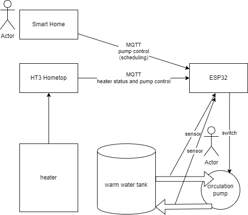
The project follows the ideas of https://github.com/MakeMagazinDE/Zirkulationspumpensteuerung and http://www.kabza.de/MyHome/CircPump/CirculationPump.php to control the hot water recirculation pump (Warmwasserzirkulationspumpe) via two temperature sensors comparing the warm water flow and return temperature. This saves electricity and thermal energy as the circulation will by done on request and not countinuously.

diagram

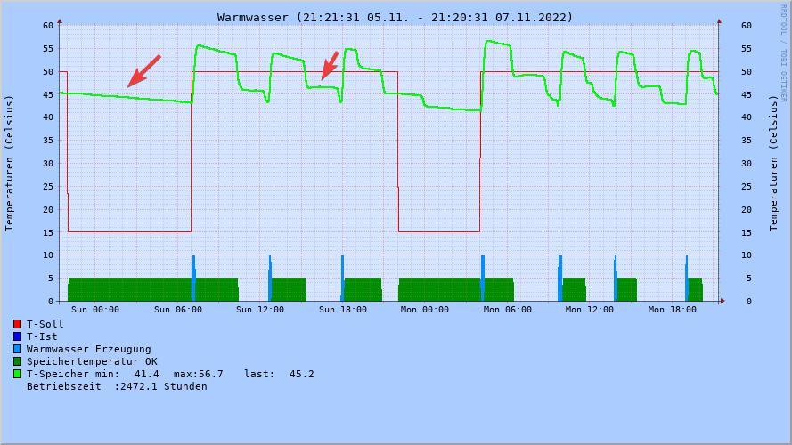
In the HT3 warm water diagram you see the period without warm water taking is flattend so the heater does heatup fewer.

warm water log

Featurelist

  • Managing the pump via flow and return temperature
  • MQTT publishing to get logging information
  • MQTT subscription for your smart home and to use heater information like provided by https://github.com/norberts1/hometop_HT3
  • Realtime clock for desinfection and logging
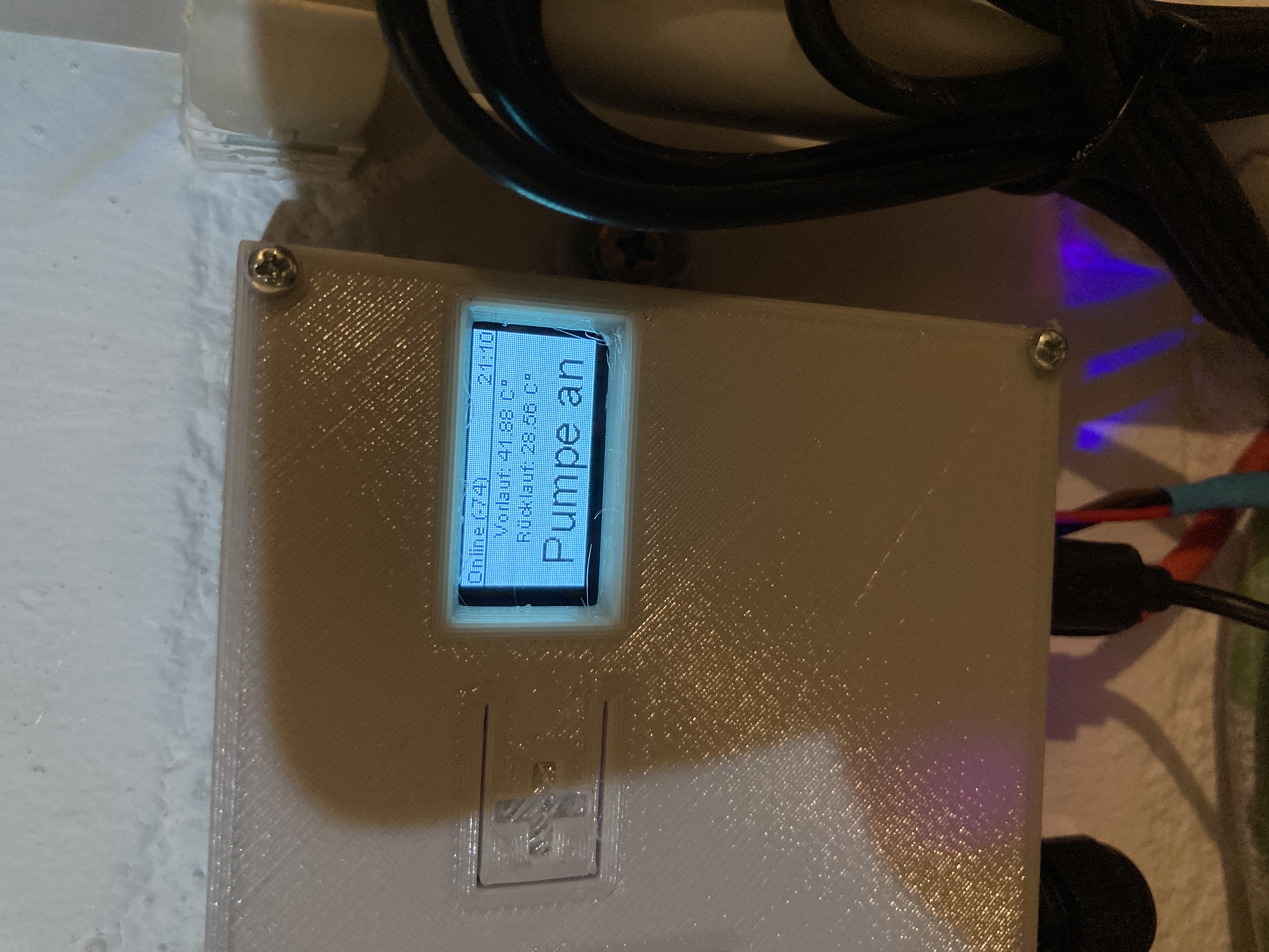
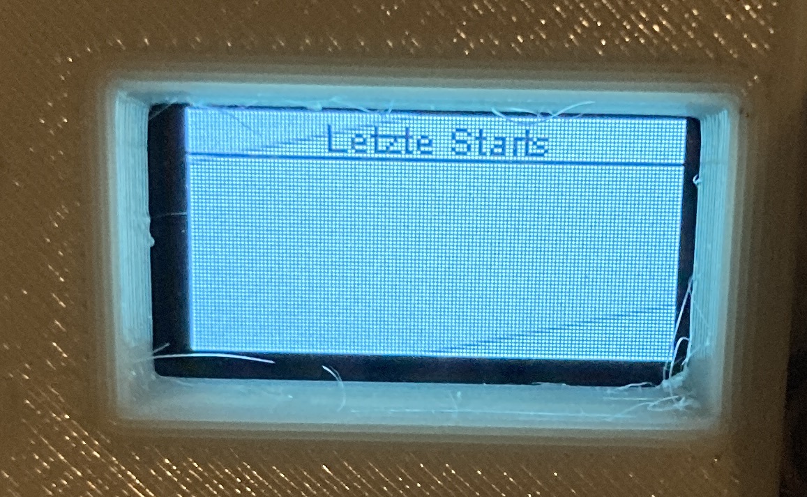
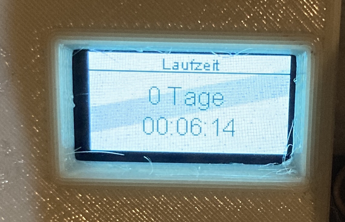
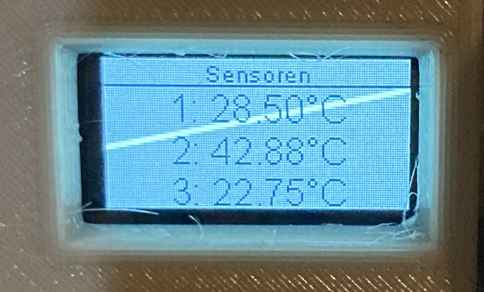
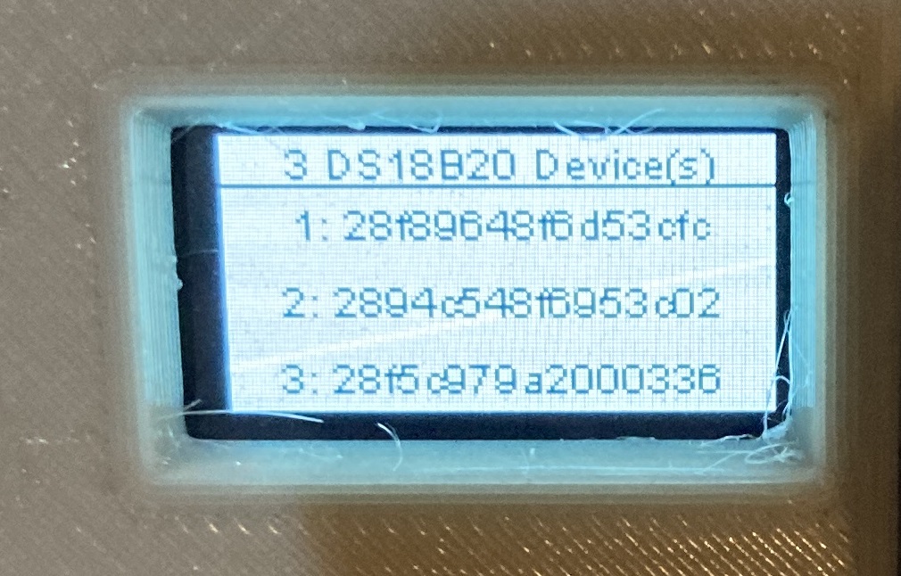
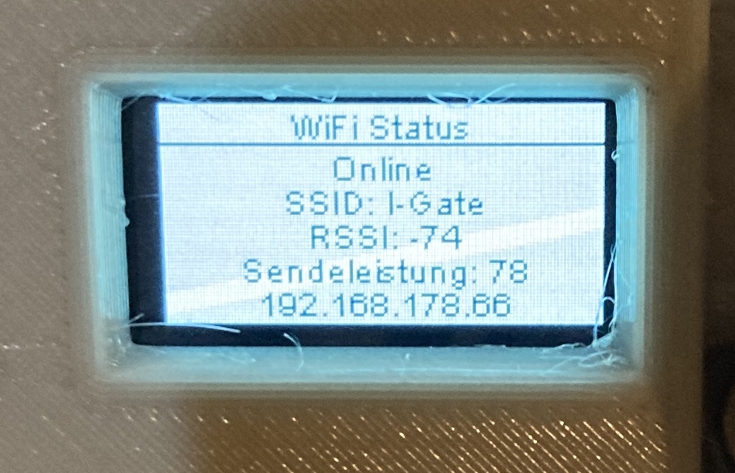
  • SSD1306 OLED to view status information
  • Guided setup to avoid storing WiFi password, etc. in the code
  • 2 channel relay to add e.g. a magnetic vent later

Hardware

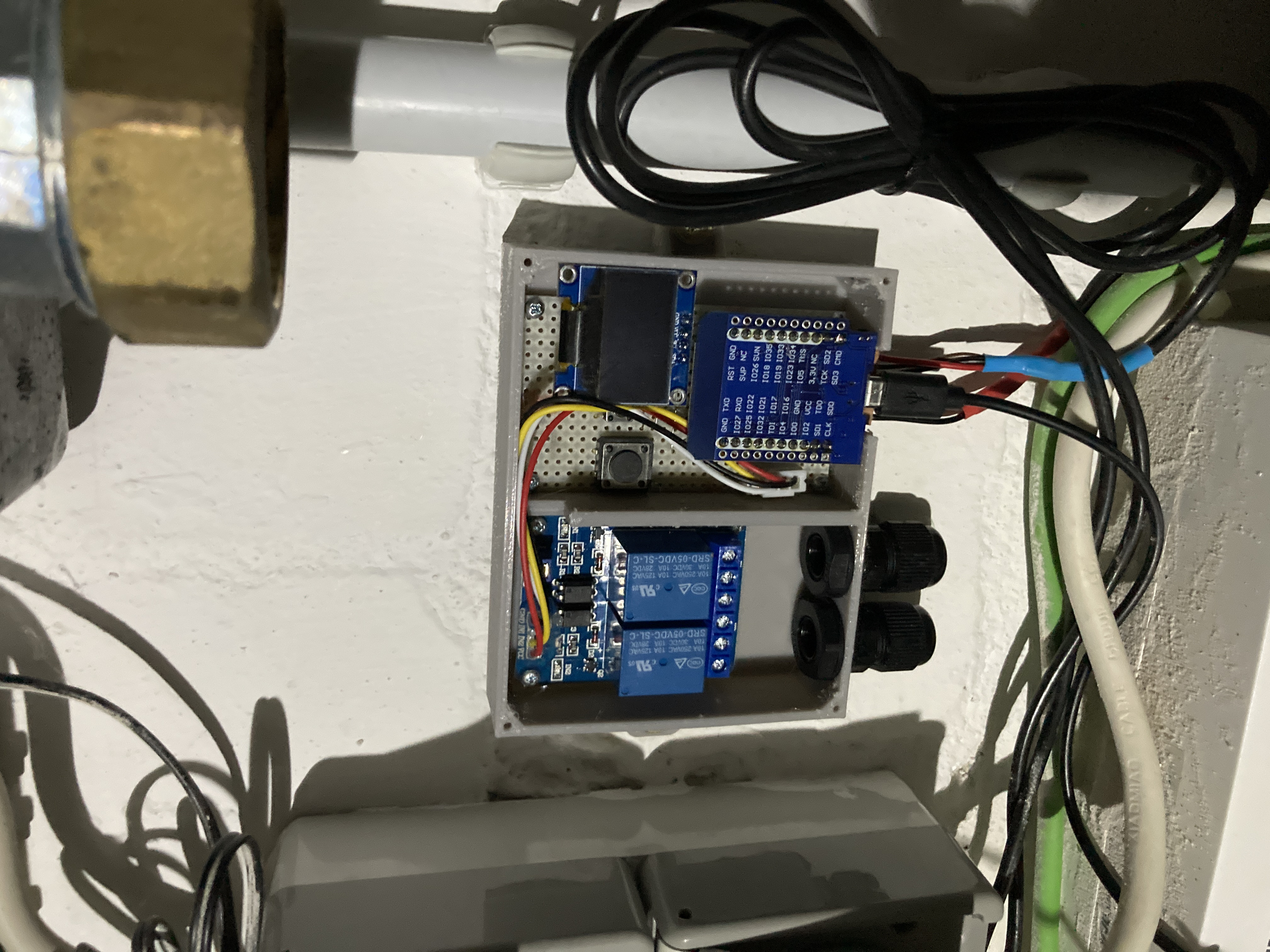
  • Wemos D1 Mini ESP32
  • Standard Arduino/Raspberry 2-channel relay with optokoppler
  • BOM
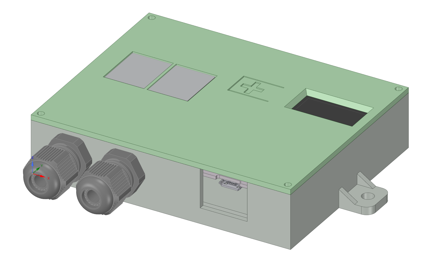
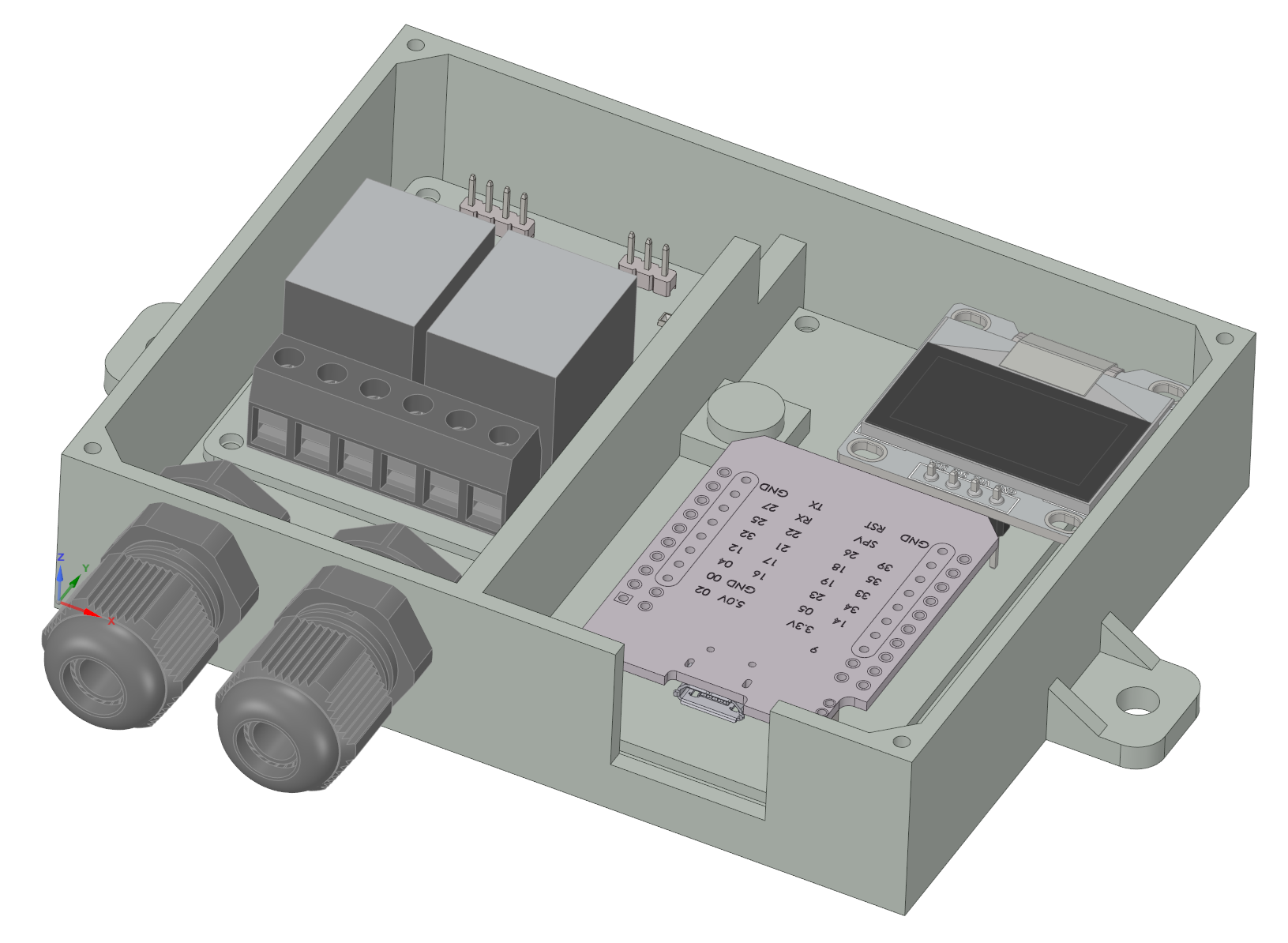
  • STL for case and cover

Case Case opened Case with components mounted

Mounting

The flow sensor have to be mounted 50cm away from the hot water reserviour. The return sensor near the end of the return pipe but not side by side to the reserviour.

Software

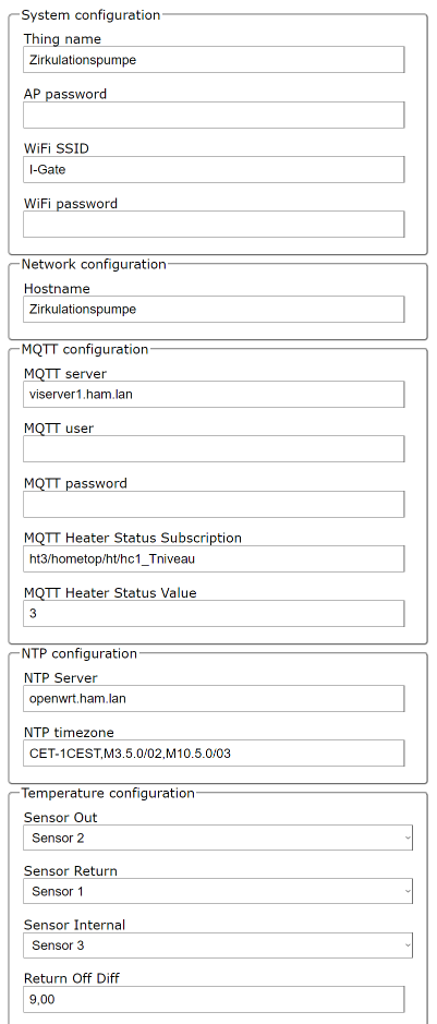
On first start the thing will open an Access Point named "Zirkulationspumpe" to provide the setup interface. The interface is still available after the device is connected so you can change everything later. But at first the firmware has to be uploaded. You can compile your own version or use the firmware provided in the releases.

  1. Do the system configuration and set things name (hostname), AP password (if WiFi connection is lost) and WiFi credentials for your network.
  2. MQTT configuration (optional)
    1. publish the following topics (folder structure can be changed):
      • "ww/ht/dhw_Tflow_measured": out temperature of the warm water
      • "ww/ht/dhw_Treturn": return temperature of the warm water circulation
      • "ww/ht/dhw_Tdelta": difference detected in the 5s time window
      • "ww/ht/Tint": system internal temperature
      • "ww/ht/dhw_pump_circulation": pump is running or not
      • "ww/ht/dhw_valve_opened": valve is currently open (true/false)
      • "ww/ht/dhw_valve_sec_opened": how many seconds the valve has been open
      • "ww/ht/dhw_valve_sec_to_refill": seconds until a refill was neccessary. Could be used for alerting purposes if there is a leakage.
      • "ww/ht/dhw_valve_pressure_avg": average system pressure value
      • "ww/ht/status": availability of the system is connected to mqtt broker (Online) or not (Offline)
      • "ww/ht/wifi": wifi related infos like signal quality
      • "ww/ht/sysinfo": status of the system showing the actual mode as Json
        • mode
          • auto - automatic mode
          • manual - control the pump via the button. The 24h timer to clean the pipes is still running.
        • state
          • heater on - temperature is watched and pump is starting automatically or by MQTT triggers
          • heater off - pump can be started by MQTT triggers
          • desinfection - Desinfection is running, all triggers are blocked until the desinfection is finished by MQTT trigger
          • emergency - some sort of problem detected like with DS18B20. The pump will start by a timer regularly.
      • "ww/ht/info": system information as text
    2. subscribe to heater topics
      • heater status topic (e.g. ht3/hometop/ht/hc1_Tniveau): if the value is matched the system switches to automatic mode. If it is not matched the pump is off and reacts on desinfection and manual starts only.
      • external pump start topic (e.g. ht3/hometop/ht/dhw_pump_circulation): The event is triggered if the message contains the value set in the configuration. The pump will swtched off if the desired return temperature is reached. Could be used to have a dump switch with HT3 and avoids buying a second IPM module for water pump (automatic mode should be disabled) or much better you can trigger the pump from your smart home or something more advanced.
      • thermal desinfection topic (e.g. ht3/hometop/ht/dhw_thermal_desinfection): if the value is matched the pump will switch on infinitly until another value is received on this topic. This can be used for desinfection topics. If desinfection is switched off the pump will still run until the necessary temperature is reached on the return pipe to guarantee the desinfection of the whole pipe.
  3. NTP configuration to get RTC infos for logging (default is fine for german timezone)
  4. Temperature configuration to map DS18B20 sensors detected
  5. Define your return temperature to switch off when the water is gone through the whole circulation pipe.
  6. button short press to swtich screen, button long press for testing the relay/pump.

config page

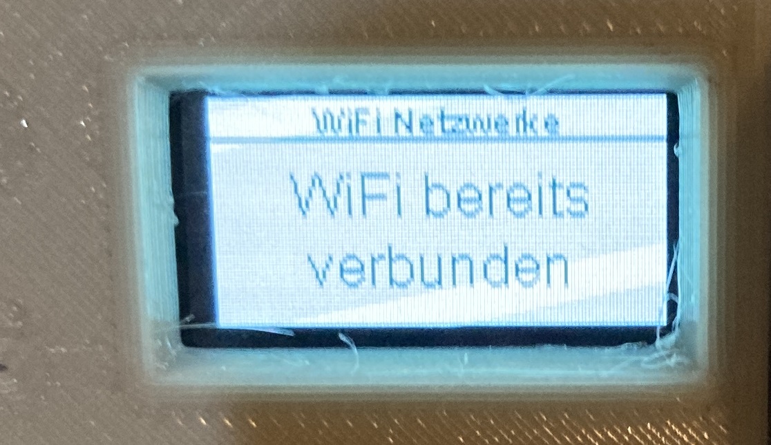
OLED infos

Tips

  • Increase the pumps flow to the maximum that the water goes through the pipes as fast as possible.
  • Setup special schedules via a smart home (MQTT) if you like to have warm water on request (e.g. by phone) or at a specific time.
  • second relay channel is actually unused - suggest how to use it if you need
  • If you are using separate networks for IoT devices it is not possible to flash the device with ArduinoOTA as it using broadcast messages that are usually dropped in the firewall. For that setup you should use HTTP upload in the config page to upload the firmware.bin.

Parts

12
QtyValueFootprintReferences
21kOhmResistor_THT:R_Axial_DIN0207_L6.3mm_D2.5mm_P10.16mm_HorizontalR1, R2
2DS18B20Connector_PinHeader_2.54mm:PinHeader_1x03_P2.54mm_VerticalJ2, J3
1BUTTON_LEDConnector_PinHeader_2.54mm:PinHeader_1x04_P2.54mm_VerticalJ4
1DISPLAY I2CConnector_PinHeader_2.54mm:PinHeader_1x04_P2.54mm_VerticalJ5
1DS18B20Package_TO_SOT_THT:TO-92_InlineU1
1Dual RelayConnector_PinHeader_2.54mm:PinHeader_1x04_P2.54mm_VerticalJ1
1SSD1306SSD1306:128x64OLEDLCD1
1SW_DISPLAY_PAGEConnector_PinHeader_2.54mm:PinHeader_1x02_P2.54mm_VerticalJ4
1SW_WIFI_CONFButton_Switch_THT:SW_PUSH_6mm_H4.3mmSW1
1mini_esp32ESP32_mini:ESP32_miniU3

Questions

What parts does the HotWaterRecirculatingPump use?

12 parts, built around the DS18B20. The full list of its parts is on this page, with links to each part's symbol and footprint where PCBKit's library has them.

Where can I download the HotWaterRecirculatingPump KiCad files?

From the NilsRo/HotWaterRecirculatingPump repository on GitHub, at the commit this page was made from: the board is kicad/HotWaterRecirculatingPump/HotWaterRecirculatingPump.kicad_pcb and its schematic kicad/HotWaterRecirculatingPump/HotWaterRecirculatingPump.kicad_sch. PCBKit opens the board in the browser, with nothing to install.

Can I use the HotWaterRecirculatingPump design in my own project?

Its repository publishes it under the AGPL-3.0 licence: you may reuse it on that licence's terms (keep the author's notice, and for a copyleft licence share your changes alike).

Similar boards

  • 2 layers33.7 × 97.8 mmHAN ESP TSS721, the printed circuit board in 3D

    HAN ESP TSS721

    UtilitechAS/amsreader-firmware

    ESP8266 and ESP32 compatible firmware to read, interpret and publish data to MQTT from smart electrical meters, both DLMS and DSMR is supported

    29 parts470
  • 2 layers121 × 68 mmFreeds sanchez, the printed circuit board in 3D

    Freeds sanchez

    pablozg/freeds

    Derivador de energía solar excedente creado por Pablo Zerón, Diseño PCB por Amcalo, Tester original por Aeizoon, Wiki por Zoilo Mora

    42 parts108
  • 2 layers80 × 54.9 mmESP32WifiAisTempVolt2, the printed circuit board in 3D

    ESP32WifiAisTempVolt2

    AK-Homberger/NMEA2000WifiGateway-with-ESP32

    This repository shows how to build a NMEA2000 WiFi Gateway with voltage and temperature alarms.

    18 parts94GPL-3.0
  • 2 layers52 × 61 mmArduino motorfocus, the printed circuit board in 3D

    Arduino motorfocus

    fehlfarbe/arduino-motorfocus

    Arduino motorfocus with moonlite protocol for telescopes

    23 parts58MIT
  • 2 layers69 × 57 mmBuoy4, the printed circuit board in 3D

    Buoy4

    wjpavalko/Maker-Buoy

    Repository of Open Source Maker Buoy Files

    46 parts39
  • 2 layers26 × 34.8 mmWemosD1Mini, the printed circuit board in 3D

    WemosD1Mini

    RuiSantosdotme/ESP8266-Multisensor-Shield

    Complete step-by-step instructions »

    10 parts29
  • 2 layers162 × 60 mmEsp shield, the printed circuit board in 3D

    Esp shield

    felixwittwer/homeassistant_automaic_greenhouse

    A cool Project to make your greenhouse smart. What about automaic irrigation and collecting enviromental data right from your garden.

    20 parts27
  • 2 layers123 × 87.5 mmFastLOGIC, the printed circuit board in 3D

    FastLOGIC

    Neumi/fastLOGIC

    An affordable Arduino-based board designed for straightforward (industrial) logic control, ideal for building small-scale automation and control solutions.

    180 parts23MIT