4 layers53.7 × 53.7 mm
RocketPower
Sanassah/RocketPower
Active fin control flight computer for a model rocket, built from scratch: custom PCB, Cortex-M7 firmware, PD attitude control, and hardware-in-the-loop testing.
133 parts6MIT

 NilsMinor/inuk-base
NRF52 controller board to create connected garden / path lights based on the fruity-mesh protocol
Inuk base is an open-source printed circuit board by NilsMinor, from the NilsMinor/inuk-base repository on GitHub. It is a 2-layer board of 100 × 70 mm with 84 parts on 73 nets, routed with 647 tracks and 167 vias.
It is built around the AP2112K-3.3, DMG3406L and B230-13-F(MS), with the BC817 among its other parts. Its parts include 29 resistors, 13 capacitors, 10 connectors, 6 transistors and 4 ICs.


This board is used in my open source smart garden light project. It is a 2 layer 70 mm x 100 mm design and serves as an NRF52 module carrier. The board is powered by one 18650 rechargeable lipo and charged by an TP4056 module with a 6V solar cell. The light interface can controll up to five pwm controlled 3W LEDs.
| Pin | Function | Note |
|---|---|---|
| P0.26 | LED D2 | high active |
| P0.27 | LED D3 | high active |
| P0.25 | BUTTON SW2 | low active |
| P0.06 | UART TX | |
| P0.08 | UART RX | |
| P0.07 | UART RTS | |
| P0.05 | UART CTS | |
| P0.02 | AIN0 | analog input - VBAT |
| P0.03 | AIN1 | analog input - VSOLAR |
| P0.04 | AIN2 | analog input |
| P0.28 | AIN4 | analog input - VLDR |
| P0.29 | AIN5 | analog input |
| P0.30 | AIN6 | analog input |
| P0.31 | AIN7 | analog input |
| P0.11 | LIO1 | pwm output led 1 |
| P0.12 | LIO2 | pwm output led 2 |
| P0.13 | LIO3 | pwm output led 3 |
| P0.14 | LIO4 | pwm output led 4 |
| P0.15 | LIO5 | pwm output led 5 |
| P0.16 | PIR INPUT | pir input - high active |
The inuk-base board is equipped with an E73-2G4M04S1B module that contains an nrf52832 SoC from nordic semiconductor. The nrf52832 bluetooth SoC comes with cortex-m4, 64K RAM and 512K ROM.
It might happen that the E73 module comes with locked UICR. In order to unlock the flash download nrfjprog from nordic. Run the following command:
nrfjprog --recoverThe output should then look like :
Recovering device. This operation might take 30s.
Erasing user code and UICR flash areas.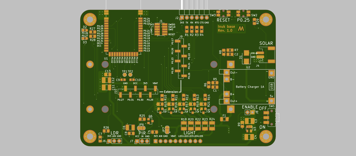
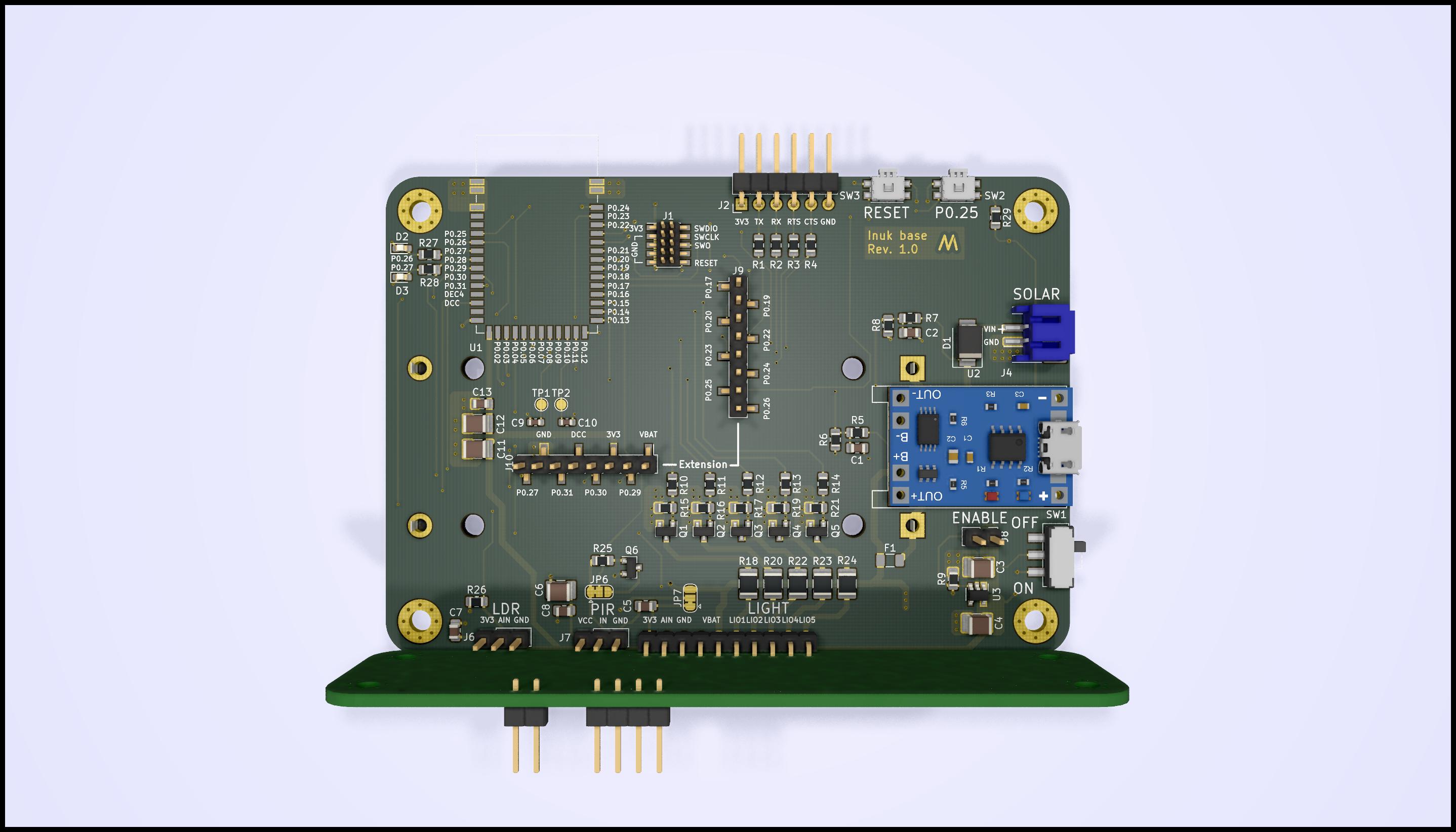
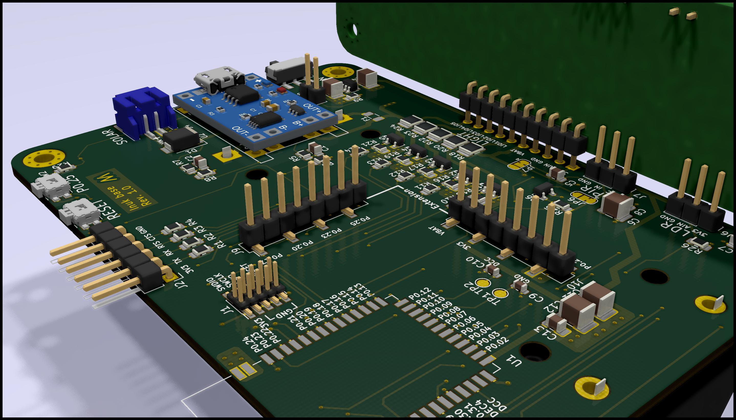
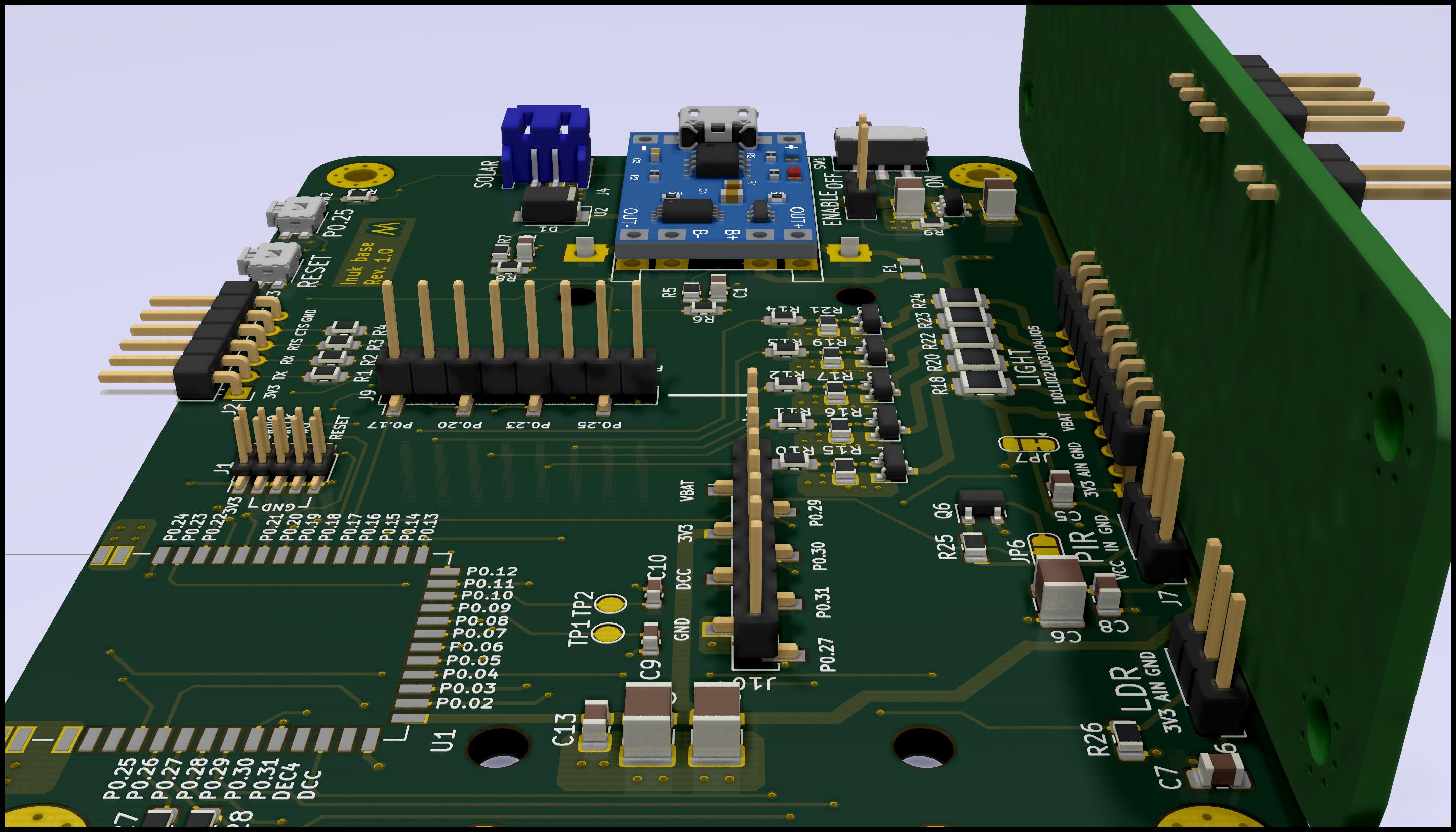
##View in 3D
| Qty | Value | Footprint | References |
|---|---|---|---|
| 9 | 100R | Resistor_SMD:R_0805_2012Metric_Pad1.15x1.40mm_HandSolder | R1, R2, R3, R4, R10, R11, R12, R13, R14 |
| 8 | 100k | Resistor_SMD:R_0805_2012Metric_Pad1.15x1.40mm_HandSolder | R9, R15, R16, R17, R19, R21, R26, R29 |
| 5 | 0R5 | Resistor_SMD:R_1210_3225Metric_Pad1.42x2.65mm_HandSolder | R18, R20, R22, R23, R24 |
| 5 | 10uF | Capacitor_SMD:C_1210_3225Metric_Pad1.42x2.65mm_HandSolder | C3, C4, C6, C11, C12 |
| 5 | DMG3406L | Package_TO_SOT_SMD:SOT-23 | Q1, Q2, Q3, Q4, Q5 |
| 5 | Jumper_NO_Small | Jumper:SolderJumper-2_P1.3mm_Open_RoundedPad1.0x1.5mm | JP1, JP2, JP3, JP4, JP5 |
| 4 | 100nF | Capacitor_SMD:C_0805_2012Metric_Pad1.15x1.40mm_HandSolder | C5, C7, C8, C13 |
| 4 | MountingHole | MountingHole:MountingHole_3.2mm_M3_Pad_Via | H1, H2, H3, H4 |
| 3 | 1k | Resistor_SMD:R_0805_2012Metric_Pad1.15x1.40mm_HandSolder | R25, R27, R28 |
| 2 | 1nF | Capacitor_SMD:C_0805_2012Metric_Pad1.15x1.40mm_HandSolder | C1, C2 |
| 2 | 2M | Resistor_SMD:R_0805_2012Metric_Pad1.15x1.40mm_HandSolder | R6, R7 |
| 2 | 806k | Resistor_SMD:R_0805_2012Metric_Pad1.15x1.40mm_HandSolder | R5, R8 |
| 2 | Battery_Cell | Battery:BatteryHolder_MPD_BH-18650-PC2 | BT1, BT2 |
| 2 | Conn_01x02_Male | Connector_JST:JST_PH_S2B-PH-SM4-TB_1x02-1MP_P2.00mm_Horizontal | J3, J4 |
| 2 | Conn_01x03_Male | Connector_PinHeader_2.54mm:PinHeader_1x03_P2.54mm_Vertical | J6, J7 |
| 2 | Conn_01x08_Male | Connector_PinHeader_2.54mm:PinHeader_1x08_P2.54mm_Vertical_SMD_Pin1Left | J9, J10 |
| 2 | LED | LED_SMD:LED_0603_1608Metric_Pad1.05x0.95mm_HandSolder | D2, D3 |
| 2 | NC | Capacitor_SMD:C_0603_1608Metric | C9, C10 |
| 2 | SW_Push | Button_Switch_SMD:Panasonic_EVQPUL_EVQPUC | SW2, SW3 |
| 2 | SolderJumper_3_Bridged12 | Jumper:SolderJumper-3_P1.3mm_Bridged12_RoundedPad1.0x1.5mm | JP6, JP7 |
| 2 | TestPoint | TestPoint:TestPoint_Pad_D1.5mm | TP1, TP2 |
| 1 | AP2112K-3.3 | Package_TO_SOT_SMD:SOT-23-5 | U3 |
| 1 | B230-13-F | Diode_SMD:D_SMB | D1 |
| 1 | BC817 | Package_TO_SOT_SMD:SOT-23 | Q6 |
| 1 | Conn_01x02_Male | Connector_PinHeader_2.54mm:PinHeader_1x02_P2.54mm_Vertical | J8 |
| 1 | Conn_01x06 | Connector_PinHeader_2.54mm:PinHeader_1x06_P2.54mm_Horizontal | J2 |
| 1 | Conn_01x08 | Custom:LED_shield | J5 |
| 1 | Conn_02x05_Odd_Even | Connector_PinHeader_1.27mm:PinHeader_2x05_P1.27mm_Vertical_SMD | J1 |
| 1 | E73-2G4M04S-52832 | RF_Module:E73-2G4M04S | U1 |
| 1 | Fuse | Fuse:Fuse_1206_3216Metric | F1 |
| 1 | Logo_NM | Custom:Logo_NM | U4 |
| 1 | SW_Push_SPDT | Button_Switch_SMD:SW_SPDT_CK-JS102011SAQN | SW1 |
| 1 | TP4056-module | Module:TP4056-module | U2 |
Sanassah/RocketPower
Active fin control flight computer for a model rocket, built from scratch: custom PCB, Cortex-M7 firmware, PD attitude control, and hardware-in-the-loop testing.

DPIclimate/ag-node
Automatic multi-weigh-station for measuring the live-weight of sheep in remote locations.


schrodlm/nxp_hal
In this assignment the target platform changes from the STM32F407 to the NXP S32K118, an Arm Cortex‑M0+ microcontroller from the S32K1xx automotive family.


JakubFranek/Home-Air-Monitoring-System
Home Air Monitoring System (HAMS) is my personal hardware & embedded software development project designed to monitor indoor and outdoor air quality in my home.

oomlout/oomlout_oomp_project_bot_v_2
It measures 100 × 70 mm and has 2 copper layers, 1.6 mm thick.
84 parts, built around the AP2112K-3.3, DMG3406L, B230-13-F(MS) and BC817. The full list of its parts is on this page, with links to each part's symbol and footprint where PCBKit's library has them.
From the NilsMinor/inuk-base repository on GitHub, at the commit this page was made from: the board is inuk-base.kicad_pcb. PCBKit opens the board in the browser, with nothing to install.
Its repository states no licence, so its author keeps all rights: ask NilsMinor before reusing the design.