2 layers82.5 × 178.8 mm
 Nils1024/magic-cube
View it interactive in your web browser:
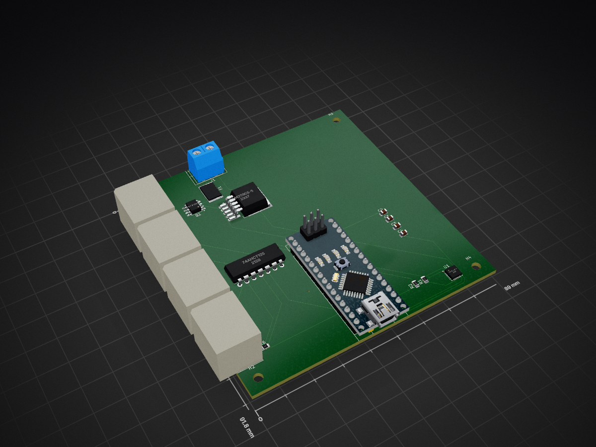
Magic cube is an open-source printed circuit board by Nils1024, from the Nils1024/magic-cube repository on GitHub. It is a 2-layer board of 89 × 91.8 mm with 28 parts on 66 nets, routed with 237 tracks and 0 vias.
It is built around the 74AHCT125D, LM2596S-5.0 and MPU-6050, with the ICS-43434 among its other parts. Its parts include 6 resistors, 5 capacitors, 5 connectors, 4 ICs and 1 transistor. It belongs with the ESP32 and AVR (ATmega, ATtiny) boards of this library.


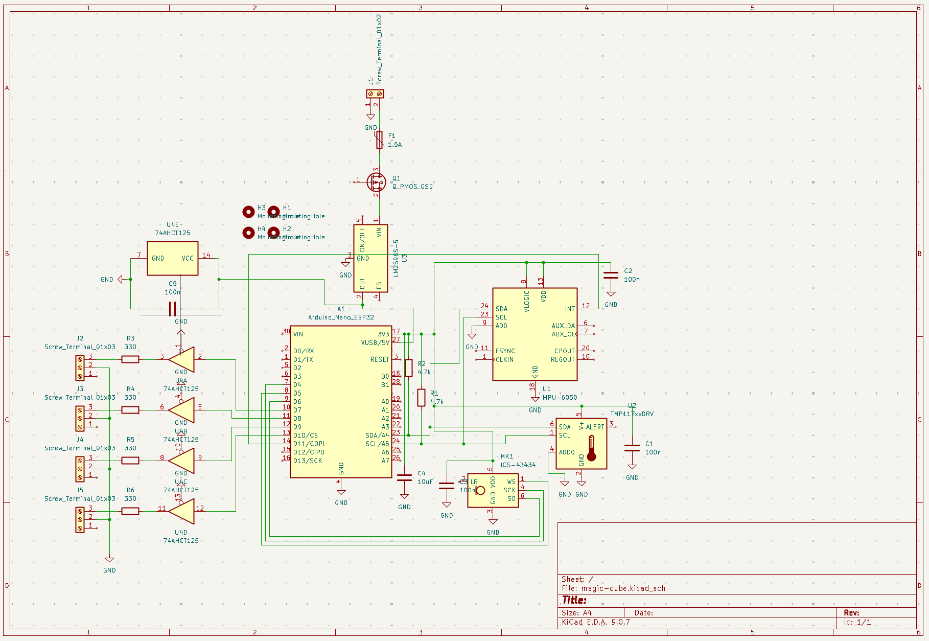
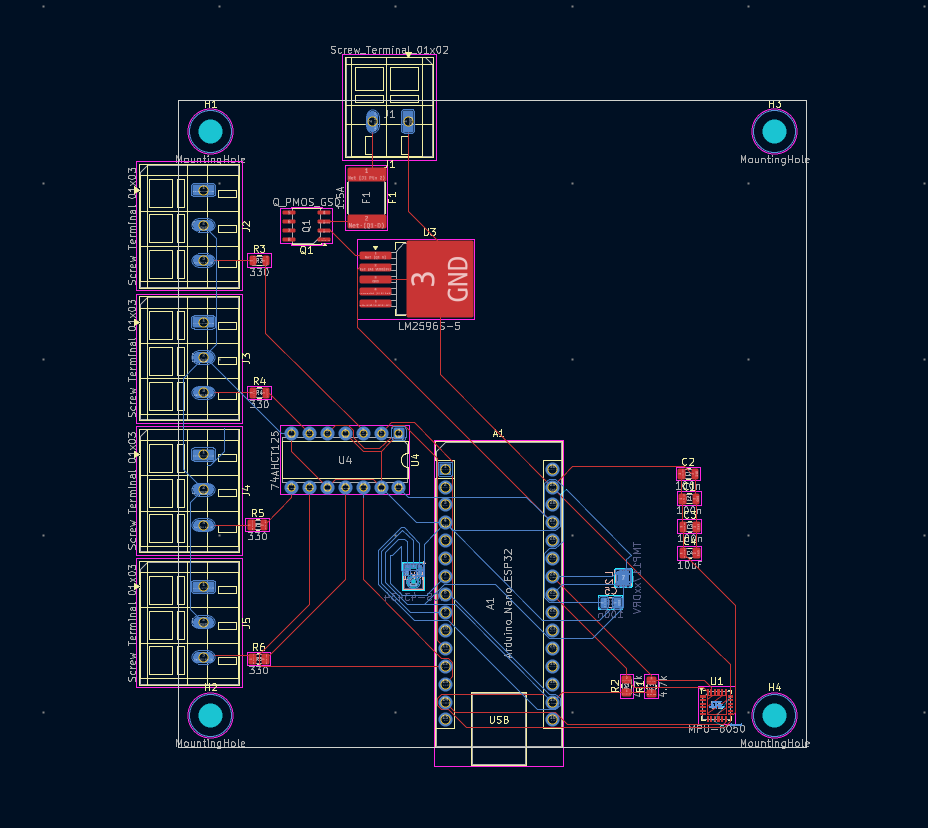
The magic cube has 4 LED Panels and they interact dynamically with the onboard sensors that are on the PCB. This includes an IMU, Temperature sensor and a microphone. Everything is also very accessible and you can always get to the power supply so you can turn it off.
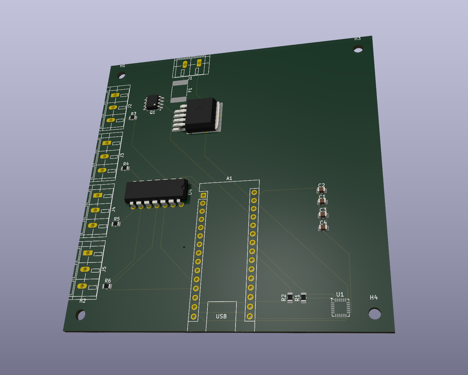
Dimensions: 89mm x 91.75mm Dimensions with terminals: 95.5mm x 98mm
Top:
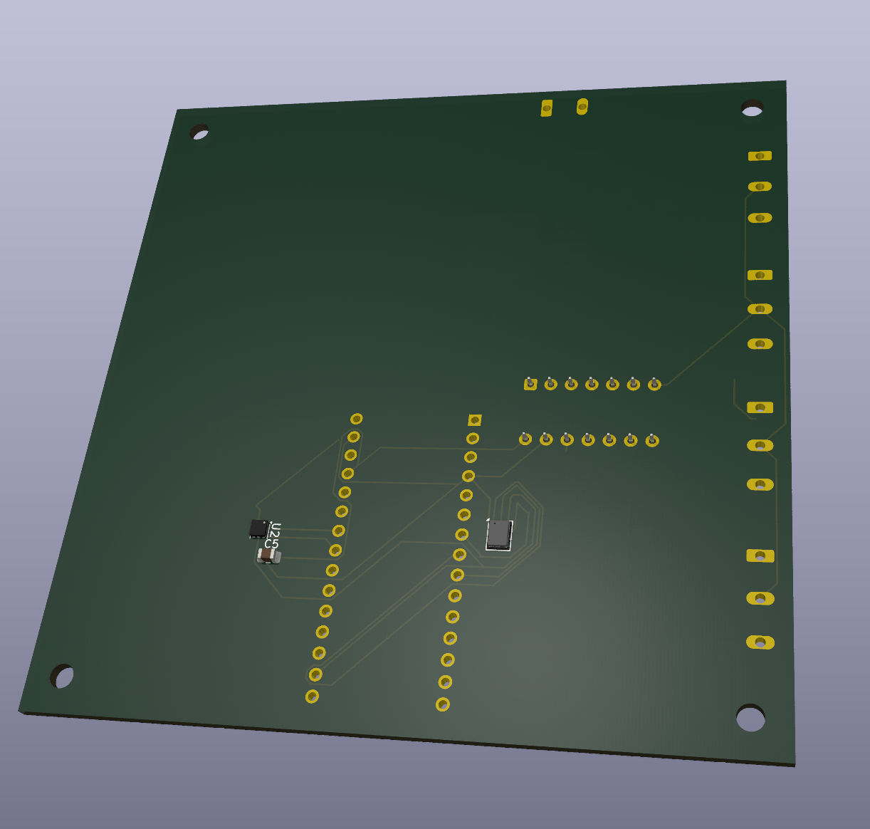
Bottom:
2D:
View it interactive in your web browser:
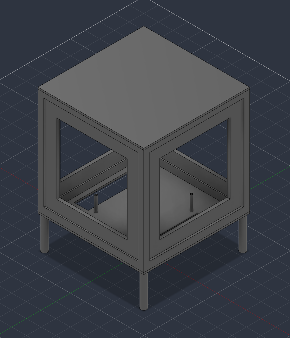
You should glue the lower part of the case with the walls together. For the cap just put it on top to maintain an easy access to all components.
Top:
Bottom:
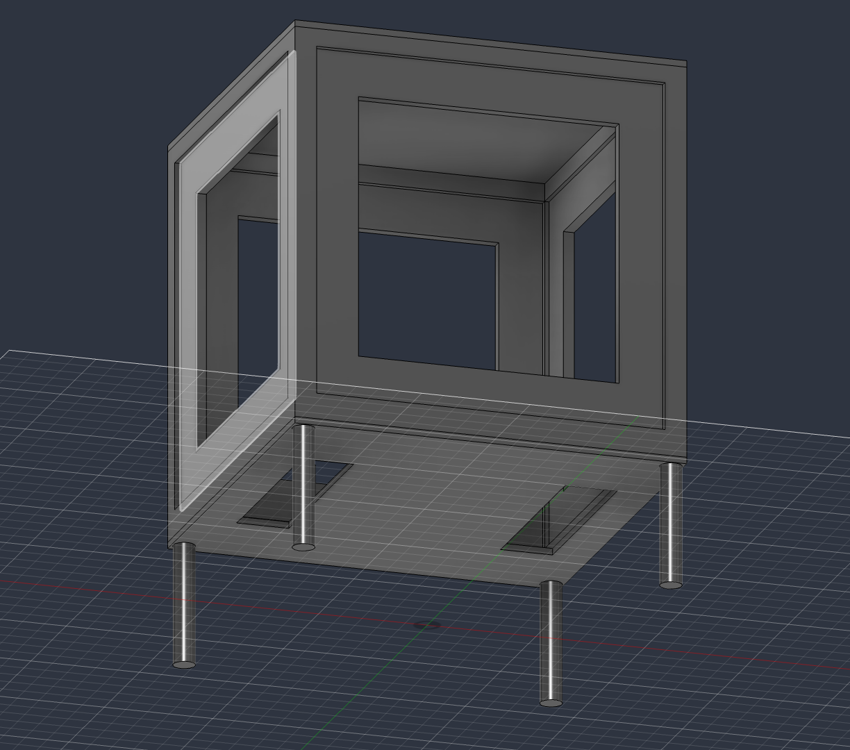
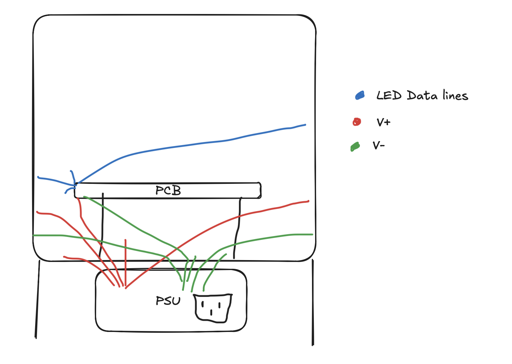
From the Power Supply one power lane to the PCB and all others to the LED Panels. All components including the PCB and LED Panels need to have the same GND. Put the cables from the PSU to the PCB through the holes at the bottom.
| Qty | Value | Footprint | References |
|---|---|---|---|
| 4 | 100n | Capacitor_SMD:C_0805_2012Metric | C1, C2, C3, C5 |
| 4 | 330 | Resistor_SMD:R_0805_2012Metric | R3, R4, R5, R6 |
| 4 | MountingHole | MountingHole:MountingHole_3mm | H1, H2, H3, H4 |
| 4 | Screw_Terminal_01x03 | TerminalBlock_WAGO:TerminalBlock_WAGO_236-103_1x03_P5.00mm_45Degree | J2, J3, J4, J5 |
| 2 | 4.7k | Resistor_SMD:R_0805_2012Metric | R1, R2 |
| 1 | 1.5A | Fuse:Fuse_2920_7451Metric | F1 |
| 1 | 10uF | Capacitor_SMD:C_0805_2012Metric | C4 |
| 1 | 74AHCT125 | Package_DIP:DIP-14_W7.62mm | U4 |
| 1 | Arduino_Nano_ESP32 | Module:Arduino_Nano | A1 |
| 1 | ICS-43434 | Sensor_Audio:InvenSense_ICS-43434-6_3.5x2.65mm | MK1 |
| 1 | LM2596S-5 | Package_TO_SOT_SMD:TO-263-5_TabPin3 | U3 |
| 1 | MPU-6050 | Sensor_Motion:InvenSense_QFN-24_4x4mm_P0.5mm | U1 |
| 1 | Q_PMOS_GSD | Package_SO:SOIC-8_3.9x4.9mm_P1.27mm | Q1 |
| 1 | Screw_Terminal_01x02 | TerminalBlock_WAGO:TerminalBlock_WAGO_236-102_1x02_P5.00mm_45Degree | J1 |
| 1 | TMP117xxDRV | Package_SON:WSON-6-1EP_2x2mm_P0.65mm_EP1x1.6mm | U2 |
It measures 89 × 91.8 mm and has 2 copper layers, 1.6 mm thick.
28 parts, built around the 74AHCT125D, LM2596S-5.0, MPU-6050 and ICS-43434. The full list of its parts is on this page, with links to each part's symbol and footprint where PCBKit's library has them.
From the Nils1024/magic-cube repository on GitHub, at the commit this page was made from: the board is pcb/magic-cube.kicad_pcb and its schematic pcb/magic-cube.kicad_sch. PCBKit opens the board in the browser, with nothing to install.
Its repository states no licence, so its author keeps all rights: ask Nils1024 before reusing the design.

themagicfrog/lightwandprogress
a pcb with neopixel lights attached and a gyroscope! for arcade and the Trail

AtharvaGupta018/my-drone-pcb-
I have recently created a drone quadcopter pcb, with no ERC and DRC errors .

Stevemwa/FMS_ESP32
This is a fleet management system that sends vehicle location data over to Firebase Cloud


DhamuVkl/ESP32S3-AI-Voice-Assistant
This project is a complete DIY AI voice assistant built around the ESP32-S3 microcontroller. It combines custom PCB design, advanced audio processing, and cloud-based AI to create a device that rivals commercial smart…

mikelawrence/esphome-indoor-multi-sensor-hardware
ESPHome Indoor Multi-Sensor hardware. This design supports Radar/PIR Presence, Temperature, Humidity, Pressure, Light, CO2, CO, VOC, NOX and PM sensors.

rowr111/blinky-badge-light
lighting badge with unique patterns and sound reactivity