
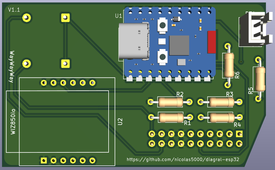
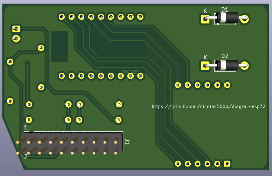
2 layers90.3 × 72.8 mm

 nicolas5000/diagral-esp326
This project permits to connect Home Assitant to your Diagral alarm system DIAG91AGFK (using the 20 pins connector on the back)
Diagral uart esp32 is an open-source printed circuit board by nicolas5000, from the nicolas5000/diagral-esp32 repository on GitHub, published under the Apache-2.0 licence. It is a 2-layer board of 69 × 43 mm with 12 parts on 30 nets, routed with 119 tracks and 1 via.
It is built around the WIZ850IO. Its parts include 6 resistors, 2 ICs, 2 diodes and 1 connector. It belongs with the interfaces and adapters boards and the ESP32 and RISC-V boards of this library.
This project permits to connect to Diagral alarm system DIAG91AGFK using the 20 pins connector on the back (the connector used for the GSM board DIAG55AAX).
It permits to get status from and modify state of the alarm system as it could be done using call and SMS with official DIAG55AAX from Diagral, but using local MQTT connection... and it is directly recognized by Home Assistant!
This project is originally tested on XIAO-ESP32-S3 (with battery management by ESP32 board) and Waveshare ESP32-C6 (with battery management by the Diagral alarm system) hardware and based on ESP-IDF SDK version 6.0.2. It should also work with any other board compatible with Waveshare ESP32-S3 and ESP32-C6 board pinout.
This project is open source: you can reuse it and modify it, but please add a link to my project. If you like this project you can contribute or buy me a coffee to support the tens of hours I spent on it :blush:.
From Diagral, DIAG55AAX (also known as DIAG55AAX1) is a 2G only mobile network board and DIAG55AAX5 is 2G/3G mobile network board. These boards will not work anymore in the future as the 2G and 3G mobile networks are being replaced by 4G and 5G networks. Of course you can buy the official Diagral 4G device to replace your old DIAG55AAX module.
The goal of this project is to connect your Diagral system locally to your Home Assistant without any Cloud based solution.
[!CAUTION] This tool is designed for educational and testing purposes, provided "as is", without warranty of any kind. It has no link with Diagral company. Creators and contributors are not responsible for any misuse or damage caused by this tool. Keep in mind that you should have a secure MQTT and Home Assistant instances to avoid any attack on your alarm system from your domotics.
To use this project in a secure way, you shall:
This documentation contains useful information about the project, especially:
I try to give support on my free time. If you have questions you can open a subject and ask directly in English (for everyone to understand) or in French.
These features are currently available:
The DIAG91AGFK has a 20-pins connector on the back to connect the DIAG55AAX GSM module. We use this connector for our project. Please check pin numbers:
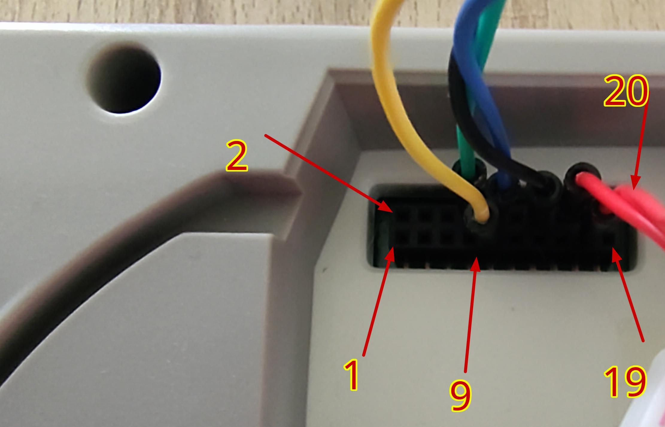
Here is the pin description for the connector:
| Pin # | Description | Used by the project? |
|---|---|---|
| 1 | Audio from DIAG91AGFK microphone, unknown format | No |
| 2 | Audio to DIAG91AGFK speaker, unknown format | No |
| 3 | Audio from DIAG91AGFK microphone, unknown format | No |
| 4 | Audio to DIAG91AGFK speaker, unknown format | No |
| 5 | GND | Yes (at least once) |
| 6 | GND | Yes (at least once) |
| 7 | Seems to be 2.8V (LVCMOS?) from DIAG91AGFK | No |
| 8 | RX for DIAG91AGFK / TX for DIAG55AAX and our project (0V at low state, 2.8V at high state) | Yes |
| 9 | "Signal" pin, low by default, set to 2.8V by DIAG91AGFK or DIAG55AAX a few ms before sending any command on corresponding TX (wake up?) | Yes |
| 10 | TX for DIAG91AGFK / RX for DIAG55AAX and our project (0V at low state, 2.8V at high state) | Yes |
| 11 | 3.3V from DIAG55AAX | No |
| 12 | Seems to be 2.8V (LVCMOS?) from DIAG91AGFK | No |
| 13 | GND | Yes (at least once) |
| 14 | GND | Yes (at least once) |
| 15 | GND | Yes (at least once) |
| 16 | Power from DIAG91AGFK | Yes (at least once) |
| 17 | +BATT from the project | Yes (at least once. If not using battery, use a 1N5819 to connect power from pin 16 or 18 to this pin) |
| 18 | Power from DIAG91AGFK | Yes (at least once) |
| 19 | +BATT from the project | Yes (at least once. If not using battery, use a 1N5819 to connect power from pin 16 or 18 to this pin) |
| 20 | +BATT from the project | Yes (at least once. If not using battery, use a 1N5819 to connect power from pin 16 or 18 to this pin) |
[!NOTE]
- It is not required to connect all GND pins as they are already connected together on DIAG91AGFK side. Connect your project board to at least 1 GND pin.
- It is not required to connect all Power pins as they are already connected together on DIAG91AGFK side. Connect your project board to at least 1 power pin.
- It is not required to connect all +BATT pins as they are already connected together on DIAG91AGFK side. Connect your project board to at least 1 +BATT pin.
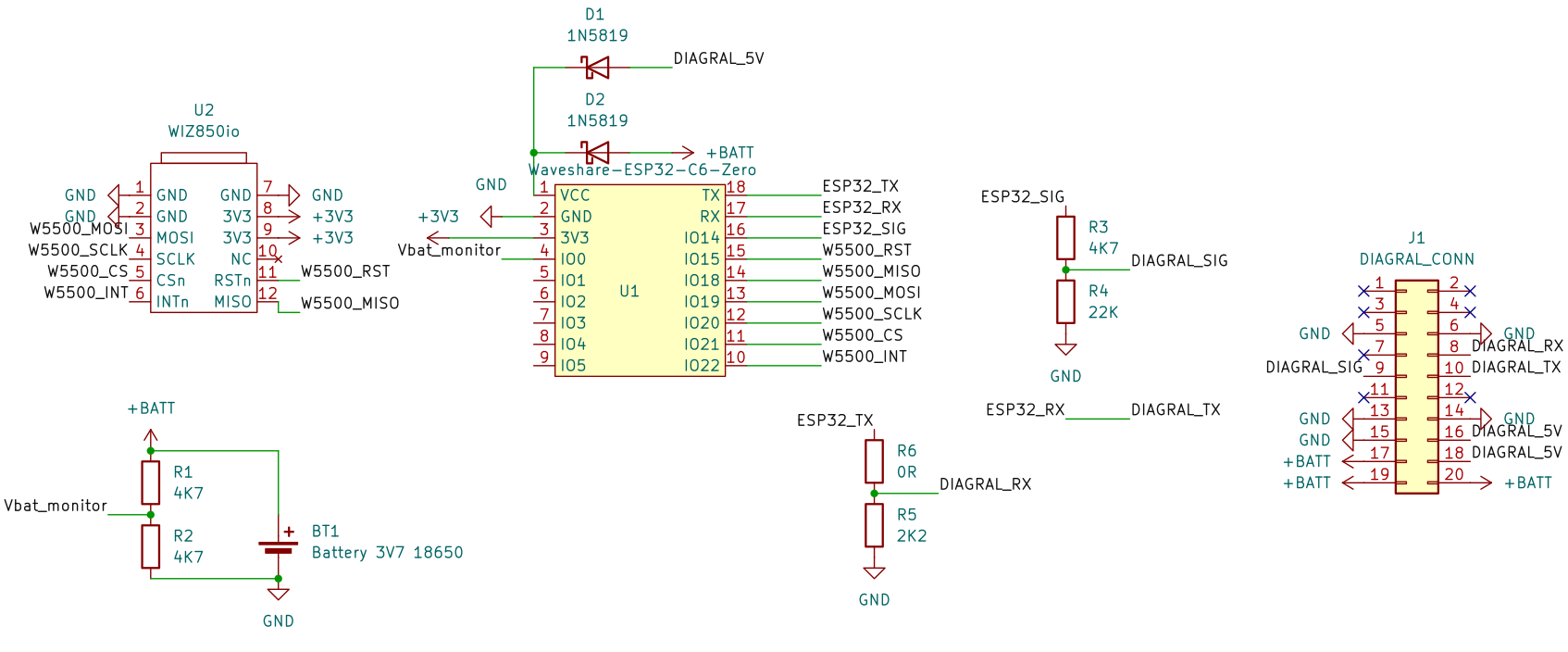 In order to use this project, you will need:
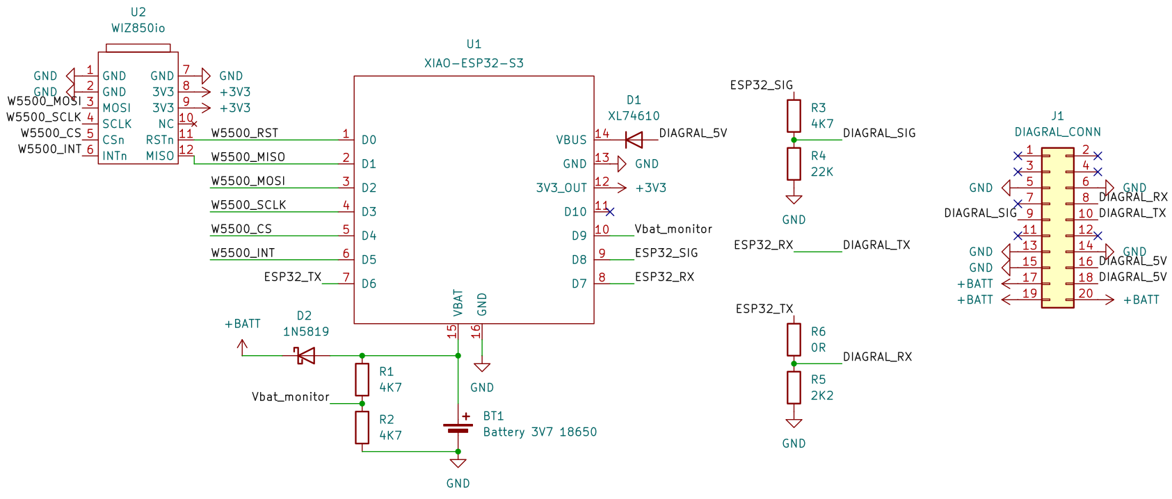
I have created a kicad project for schematics and PCB routing. Current version of the PCB is 1.1.
You can directly purchase a PCB (minimum order of 5 units) from PCBWay using this link or ask me for available PCB and passive components (I don't provide ESP32, W5500 and battery and I don't solder the components).
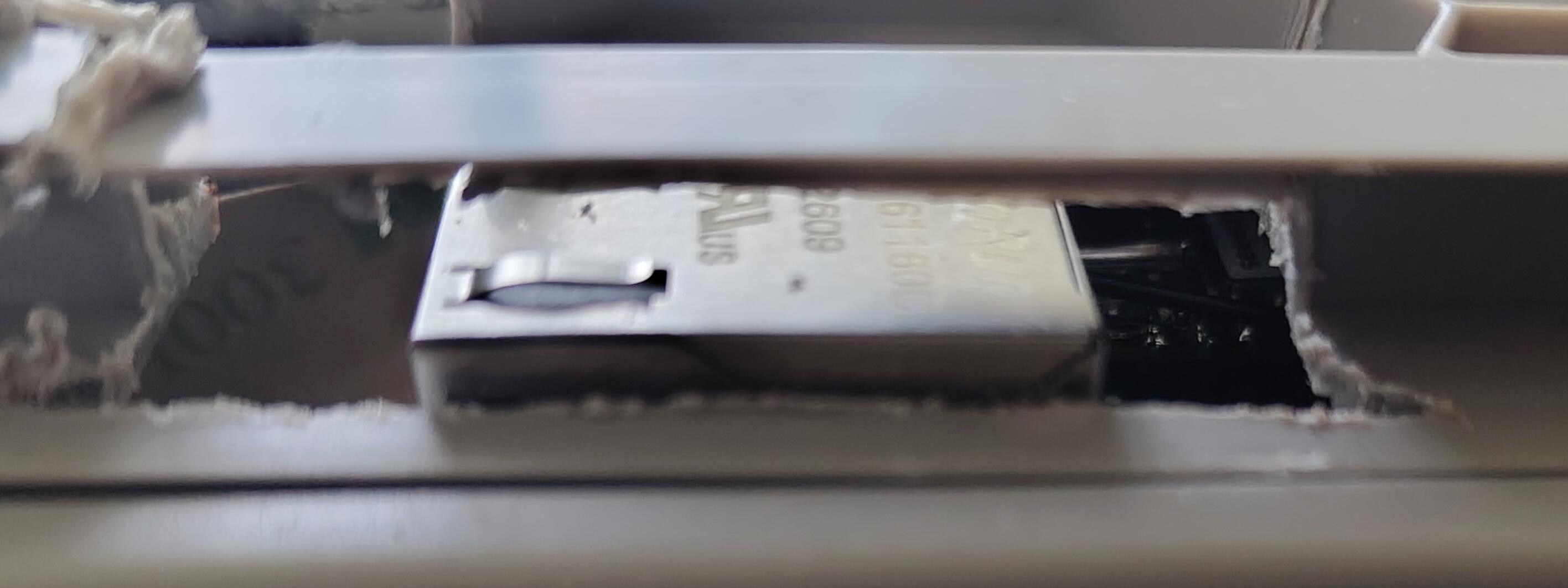
[!CAUTION] Please note that mounting the W5500 module to use the Ethernet link will require to cut the back of the DIAG91AGFK because the W5500 is too big as you can see:
| PCB # | ESP32 compatibility | Limitations |
|---|---|---|
| beta | Seeed Studio XIAO-ESP32-S3 | (1) (2) |
| 1.0 | Seeed Studio XIAO-ESP32-S3 | (2) |
| 1.1 | Waveshare ESP32-C6-Zero or ESP32-S3-Zero (or equivalent pinout and footprint) | No known limitation |
Known limitations:
| PCB # | PCB price | Passive components (optional) | Quantity available |
|---|---|---|---|
| beta | 3€ | 2€ for 20-pin connector, 1x 1N5819, 1x XL74610, 3x 4.7k resistors, 1x 22k resistor, 1x 2.2k resistor | 3 (in stock) |
| 1.0 | 3€ | 2€ for 20-pin connector, 1x 1N5819, 1x XL74610, 3x 4.7k resistors, 1x 22k resistor, 1x 2.2k resistor | 4 (in stock) |
| 1.1 | 5€ | 1€ for 20-pin connector, 2x 1N5819, 3x 4.7k resistors, 1x 22k resistor, 1x 2.2k resistor | on demand |
Additional costs for packaging and shipping to France (bubble envelope with tracking number) : 4€
[!NOTE] Not included: ESP32, W5500 Ethernet module, battery and its connector, soldering the components on the PCB.
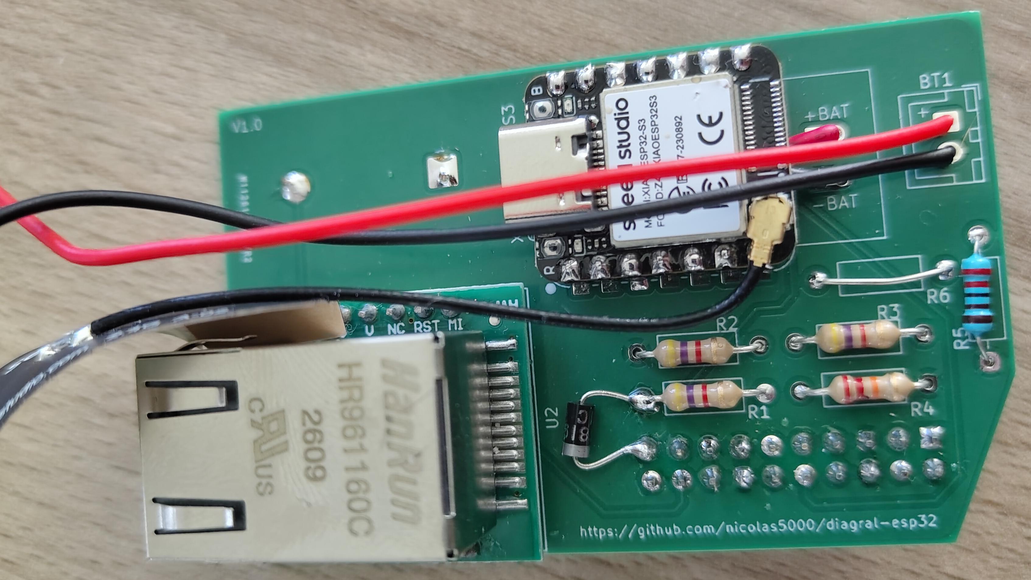
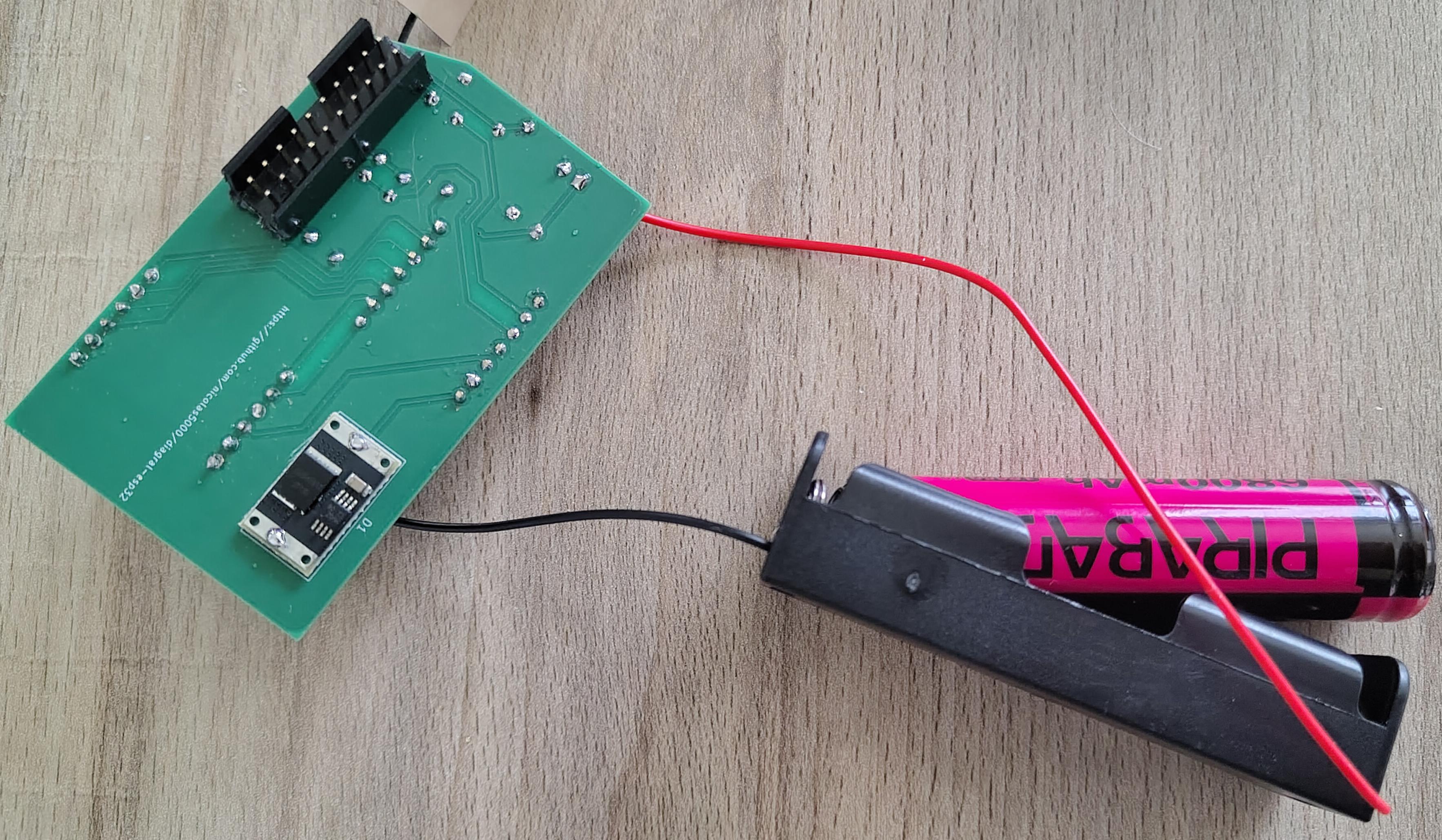
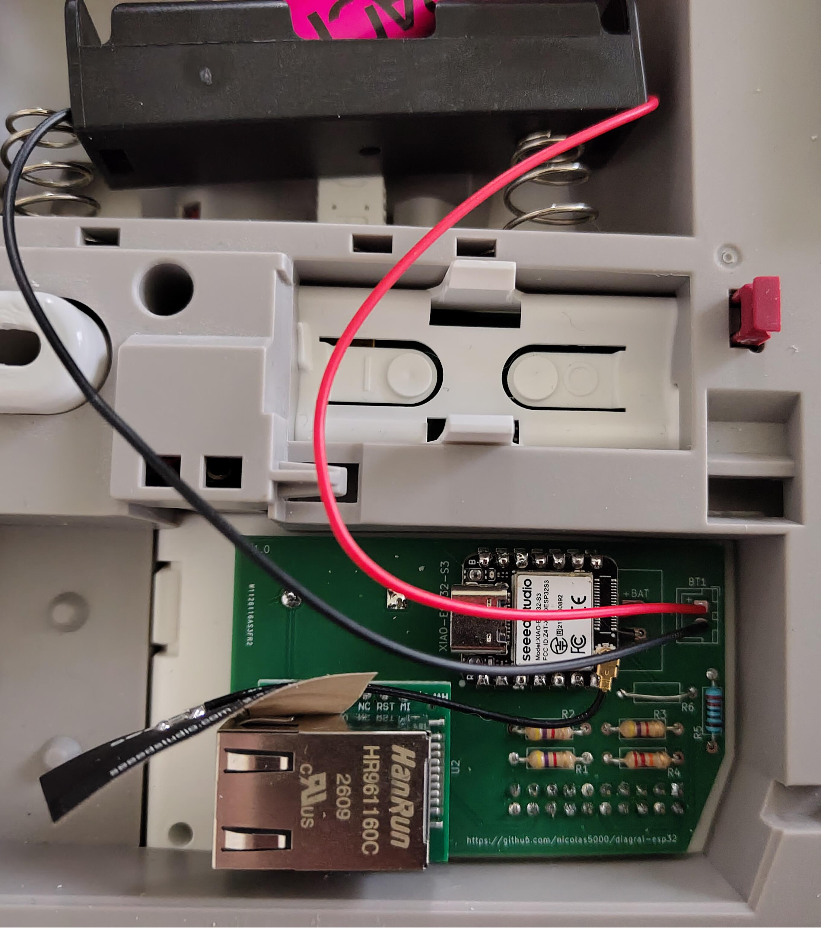
Here is an example of components on PCB 1.0:
The development environment is based on:
Here are a few steps to follow to start with this project:
By default the project is configured with verbose enabled and not in passive mode: you can see what happens with detailed logs and you can control your Diagral alarm system. In active mode you can use the command line to send commands to your Diagral system. You can use passive mode to get frames from DIAG91AGFK to DIAG55AAX only (but you have to connect all 20 pins).
As previously explained, in passive mode (don't forget to enable verbose) you will get frames from DIAG91AGFK to DIAG55AAX only. If you need to see all exchanges you will have to use another "spy UART project".
In this mode you can control your alarm system.
[!NOTE] Keep verbose enabled if you want to see what happens in Diagral UART layer. In addition to console, exchanged frames can be sent to a Syslog server.
In order to update the firmware from Wifi or Ethernet securely, you should use an HTTPS server. If you don't mind, you can also use a simple HTTP server. This section describes the 2 options.
Saving the URL no longer starts an update: it is stored in NVS and reused when the OTA Upgrade button is pressed. Clearing the URL disables the button. The download runs in a separate task so it does not block the MQTT event handler. See the MQTT OTA workflow for URL requirements, command topics and status values.
Keep the update server restricted to your trusted local network. Do not expose it to the Internet.
[!NOTE] After OTA is performed, the ESP32 will reboot automatically. Then, if MQTT is not able to connect within 60s, the rollback will be performed to reboot on previous firmware.
openssl req -x509 -newkey rsa:2048 -keyout ca_key.pem -out ca_cert.pem -days 365 -nodes. Don't forget to use a CN field that matches the machine IP address or name (like myserver.lan) that will be used in the URL when performing OTA. Note: this file is required to build and be included within the first firmware to load using USB.python3 tools/simple_ota_https_server.py <BIN_DIR> <PORT> [CERT_DIR] --bind <LAN_IP>. Use a certificate containing the same IP address or hostname used in the firmware URL, including its subject alternative name.https://myserver.lan:8070/diagral-uart-esp32.bin assuming you are using port 8070 on machine myserver.lanThe HTTPS helper requires Python 3.10 or newer and existing ca_cert.pem / ca_key.pem files. Keep the key outside the served directory and outside Git; the optional CERT_DIR selects their location and defaults to BIN_DIR. All relative paths are resolved from the current working directory. The helper never generates or overwrites certificates or keys.
The default bind address is 127.0.0.1, so an explicit trusted LAN address is needed for ESP32 access. Only diagral-uart-esp32.bin is served by default, for GET and HEAD requests; directory listings and certificate/key paths are unavailable. Use --file <FILENAME.bin> to select another binary and --allow-subnet <CIDR> to restrict clients to your LAN subnet. Symlinks are not accepted as the selected firmware file. Stop the server with Ctrl+C after the update.
For example, with LAN address 192.168.1.18 and subnet 192.168.1.0/24:
python3 tools/simple_ota_https_server.py build 8443 ../ota-certificates --bind 192.168.1.18 --allow-subnet 192.168.1.0/24The helper tests run with python3 -m unittest discover -s tools -p test_simple_ota_https_server.py -v. HTTPS tests use a temporary certificate generated by OpenSSL; those tests are skipped if OpenSSL is unavailable, and the symlink test is skipped where creation is not permitted.
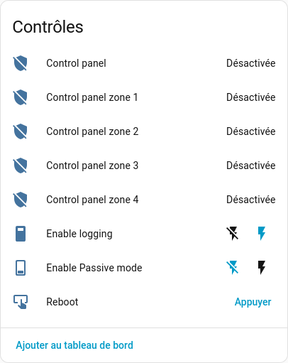
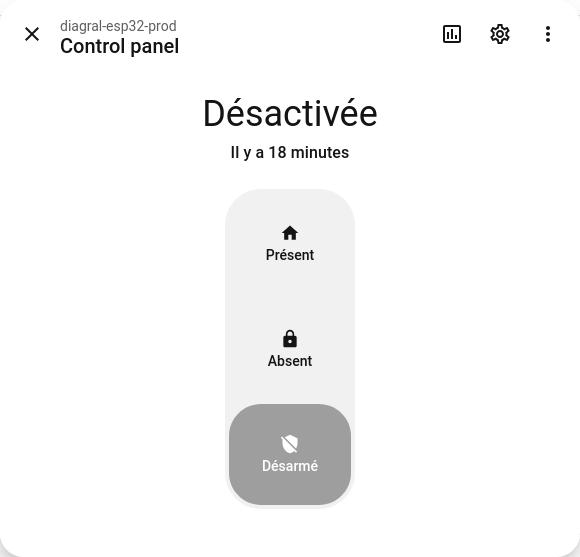
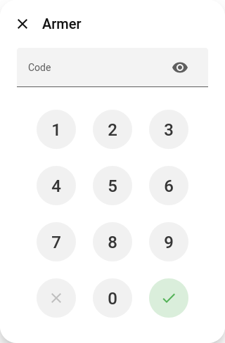
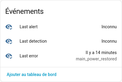
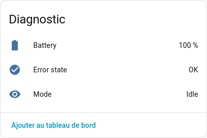
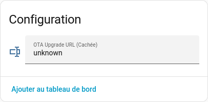
python3 -m http.server 8070 --bind :: in the build folder containing diagral-uart-esp32.binhttp://myserver.lan:8070/diagral-uart-esp32.bin assuming you are using port 8070 on machine myserver.lanThe board will be automatically discovered by Home Assistant MQTT integration and provide controls (with control panel for all zones and for each zone), PIN code verification (if enabled in the configuration), events (detection, alert, error), diagnostics and OTA firmware update.
You can mainly contribute to this project by:
| Qty | Value | Footprint | References |
|---|---|---|---|
| 3 | 4K7 | Resistor_THT:R_Axial_DIN0207_L6.3mm_D2.5mm_P10.16mm_Horizontal | R1, R2, R3 |
| 2 | 1N5819 | Diode_THT:D_DO-41_SOD81_P10.16mm_Horizontal | D1, D2 |
| 1 | 0R | Resistor_THT:R_Axial_DIN0207_L6.3mm_D2.5mm_P10.16mm_Horizontal | R6 |
| 1 | 22K | Resistor_THT:R_Axial_DIN0207_L6.3mm_D2.5mm_P10.16mm_Horizontal | R4 |
| 1 | 2K2 | Resistor_THT:R_Axial_DIN0207_L6.3mm_D2.5mm_P10.16mm_Horizontal | R5 |
| 1 | Battery 3V7 18650 | Connector_JST:JST_XH_B2B-XH-A_1x02_P2.50mm_Vertical | BT1 |
| 1 | DIAGRAL_CONN | my_library:PinHeader_2x10_P2.54mm_Vertical | J1 |
| 1 | WIZ850io | my_library:WIZ850io | U2 |
| 1 | Waveshare-ESP32-C6-Zero | my_library:Waveshare-ESP32-C6-Zero | U1 |

kellerkindt/bluepill_sensor
Bluepill stm31f103 ethernet sensor extension board with SW written in Rust


bablokb/pcb-datalogger-v4e
Pico Board for Data-Logging (Ethernet Version)

flintwinters/helix-hardware
KiCad 10 schematic for a USB powered STM32C071FBP6 with one shared SPI bus. The WIZ850io W5500 module and a 3.3 V, six wire microSD SPI breakout have separate chip selects. SWD is available for first firmware bring-up.

JoachimBose/nabby-linux
An Allwinner F1C100s / F1C200s buildroot external tree for (among others) the hardware challenge for VUCTF-2026


It measures 69 × 43 mm and has 2 copper layers, 1.6 mm thick.
12 parts, built around the WIZ850IO. The full list of its parts is on this page, with links to each part's symbol and footprint where PCBKit's library has them.
From the nicolas5000/diagral-esp32 repository on GitHub, at the commit this page was made from: the board is kicad/diagral-uart-esp32.kicad_pcb and its schematic kicad/diagral-uart-esp32.kicad_sch. PCBKit opens the board in the browser, with nothing to install.
Its repository publishes it under the Apache-2.0 licence: you may reuse it on that licence's terms (keep the author's notice, and for a copyleft licence share your changes alike).