Skip to the content
PCBKitNew board
2 layers313.9 × 119.4 mmDissatisfaction-65, the printed circuit board in 3D

Dissatisfaction-65

Nicell/Dissatisfaction-6586

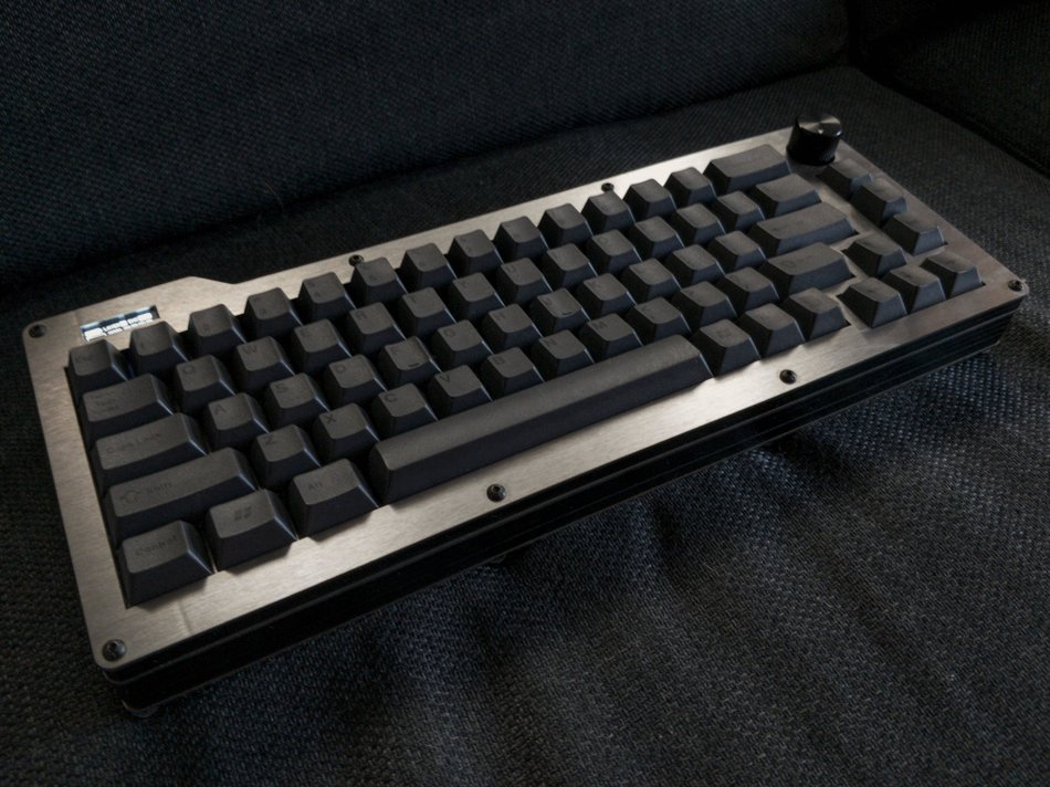
A 65% QMK Bluetooth keyboard with an OLED and encoder

Size
313.9 × 119.4 mm
Copper layers
2
Thickness
1.6 mm
Parts
139
Nets
111
Pads
550
Tracks, vias
634, 47
Routed
Yes
KiCad
KiCad 5 (file 20171130)
Created
6 Feb 2020
Updated
9 Feb 2020

Overview

Dissatisfaction-65 is an open-source printed circuit board by Nicell, from the Nicell/Dissatisfaction-65 repository on GitHub, published under the MIT licence. It is a 2-layer board of 313.9 × 119.4 mm with 139 parts on 111 nets, routed with 634 tracks and 47 vias.

It is built around the 74HC4514D. Its parts include 67 diodes, 3 ICs and 2 switches. It belongs with the keyboards and input and radio and wireless boards of this library.

Main components

1

README

README.md

Dissatisfaction65

This is the hardware repository for my 65% QMK Bluetooth keyboard with an OLED and encoder.

I'm working on a new version of this to vastly improve the design and functionality. You can follow the development on this discord

Software (QMK)

You can currently find the firmware for this board at my qmk-firmware fork. It requires this pull-request before it can be fully upstreamed.

What you'll need (or at least what I used)

You can get most of these items at different places, but I left the more convenient places here. Often you can get cheaper electronics at LCSC and AliExpress rather than Mouser and Amazon.

  • Adafruit Feather 32u4 Bluefruit LE BUY
  • 2500mAH battery or equivalent (probably don't go thicker) BUY
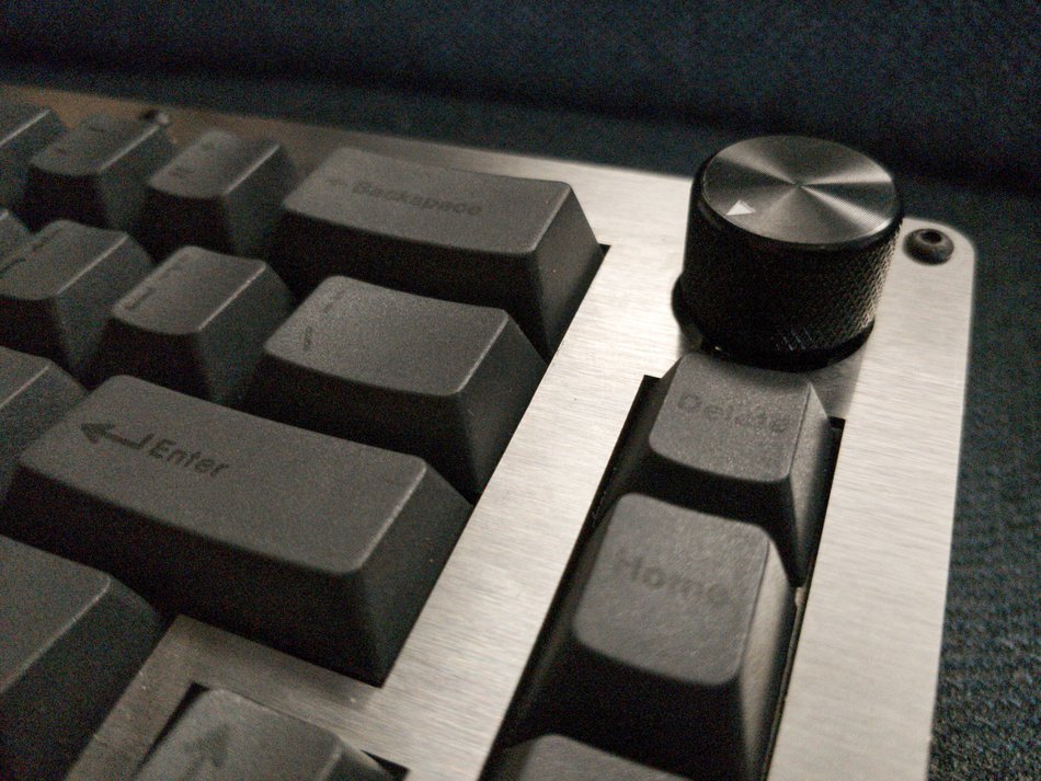
  • EC12 Encoder Knob BUY
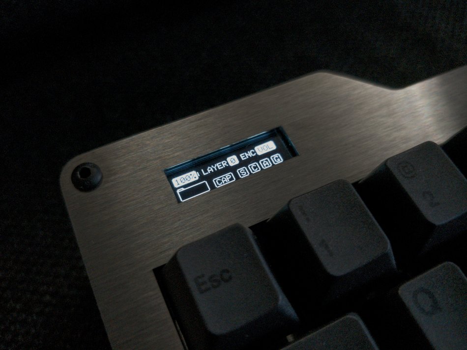
  • OLED SSD1306 128x32 BUY
  • Long headers for the OLED to reach far down BUY
  • 1N4148 DO-35 package 67x BUY
  • 74HC4515 Decoder BUY
  • On-Off switch BUY
  • Encoder Knob BUY
  • M3 (Bolts) (Nuts) (Lock Nuts) (Rubber Feet)
  • Plates: one of each of the plates found in the DXF folder. Middle MUST be 1.5mm. I got mine from SendCutSend in brushed stainless steel using the combined plates file. I highly recommend them. Fast, affordable, and good quality.
  • Middle pieces: 7x of the middle piece found in the DXF folder. I used 1/8in thick pieces. 2x between the top and switch plate, and 5x between the bottom and switch plate. The second and third to last from the bottom pieces need cutouts for both the micro USB and the power switch. I got mine from Sculpteo. I would not recommend them. The wait was long, the order was messed up, and the quality was very mediocre. There was an obvious taper on the cuts.
  • MX style switches 67x. PCB or plate mount
  • Keycaps! KLE can be found here.

Things I'd like to change

There were a few things that I'd like to change. I haven't done them yet, but they would enhance the board.

  • Move the encoder switch to the matrix. Currently has its own direct connection.
  • Recreate the switch plate using ai03's plate designer. Currently has huge lines across stabs and the stab holes are really tight.
  • Re-dimension the OLED. It seems to be barely too far down and to the left. I can re-dimension now that I have calipers.
  • Redo the decoder using a 74HC154. No need to use the latched version that's more expensive and slower.
  • Create a little cut in the middle pieces to use as a prop up for the OLED.
  • Create pre-made middle pieces with cutouts for the micro USB port and the on-off switch rather than cutting them manually.

Random things I encountered

  • Make sure to test your Adafruit board fully before soldering it in. The board I got had a working MCU and Bluetooth module, but they couldn't communicate properly despite continuity between the SPI pins.
  • My plate ended up flexing a bit when connecting the switches. I suspect the PCB was either a bit too small or the plate was a bit too big. I really don't know why this was the case.

Thanks to

  • QMK team for helping me with getting the firmware working
  • Nick_68 and WoodKeys for each of their iterations on the Bluetooth + decoder design with the Ronin and Meira, which were invaluable for me while I was designing this board.
  • ai03 for the MX KiCad library I have in this project.

Images

Full OLED Encoder

Parts

139
QtyValueFootprintReferences
67D_SmallDiode_THT:D_DO-35_SOD27_P7.62mm_HorizontalD1, D2, D10, D11, D12, D13, D14, D15, D16, D17, D18, D19, D20, D21, D22, D23 +51
56MX-NoLEDMX_Only:MXOnly-1U-NoLEDMX_-1, MX_,1, MX_;1, MX_.1, MX_'1, MX_/1, MX_0, MX_1, MX_2, MX_3, MX_4, MX_5, MX_6, MX_7, MX_8, MX_9 +40
3MX-NoLEDMX_Only:MXOnly-1.25U-NoLEDMX_LALT1, MX_LCTRL1, MX_WIN1
2MX-NoLEDMX_Only:MXOnly-1.5U-NoLEDMX_\1, MX_TAB1
2MX-NoLEDMX_Only:MXOnly-1.75U-NoLEDMX_CLCK1, MX_RSHIFT1
2MX-NoLEDMX_Only:MXOnly-2.25U-NoLEDMX_ENTER1, MX_LSHIFT1
174HC4514Package_SO:SOIC-24W_7.5x15.4mm_P1.27mmU2
1Adafruit_Feather_32u4_Bluefruit_LEDissatisfaction65:Adafruit_Feather_32u4_Bluefruit_LEU1
1MX-NoLEDMX_Only:MXOnly-2U-NoLEDMX_BKSP1
1MX-NoLEDMX_Only:MXOnly-6.25U-ReversedStabilizers-NoLEDMX_SPC1
1Rotary_Encoder_SwitchRotary_Encoder:RotaryEncoder_Alps_EC11E-Switch_Vertical_H20mmSW1
1SSD1306_I2CDissatisfaction65:OLEDU3
1SW_SPSTConnector_PinHeader_2.54mm:PinHeader_1x02_P2.54mm_VerticalSW2

Questions

How big is the Dissatisfaction-65 PCB?

It measures 313.9 × 119.4 mm and has 2 copper layers, 1.6 mm thick.

What parts does the Dissatisfaction-65 use?

139 parts, built around the 74HC4514D. The full list of its parts is on this page, with links to each part's symbol and footprint where PCBKit's library has them.

Where can I download the Dissatisfaction-65 KiCad files?

From the Nicell/Dissatisfaction-65 repository on GitHub, at the commit this page was made from: the board is PCB/Dissatisfaction65.kicad_pcb. PCBKit opens the board in the browser, with nothing to install.

Can I use the Dissatisfaction-65 design in my own project?

Its repository publishes it under the MIT licence: you may reuse it on that licence's terms (keep the author's notice, and for a copyleft licence share your changes alike).

Similar boards

  • 2 layers313.9 × 119.4 mmCMKC65 R1, the printed circuit board in 3D

    CMKC65 R1

    thomasdevine01/cmkc-keyboard

    Chico State Mechanical Keyboard Club's Keyboard and Firmware Design

    141 parts2MIT
  • 2 layers44.5 × 46.4 mmUsb tester, the printed circuit board in 3D

    Usb tester

    Disasm/usb-tester

    22 parts1
  • 4 layers220 × 200 mmQuadrant, the printed circuit board in 3D

    Quadrant

    etiennechlt/electronic-chess

    Générée par tools/boardgen (module power). 100 x 60 mm, 2 couches, plan de masse en face arrière. Elle gère trois cellules plates 1S 5 Ah.

    347 parts
  • 4 layers228.6 × 110.7 mmDriver test, the printed circuit board in 3D

    Driver test

    thewonderidiot/lachesis

    Portable, safe readers for Apollo Guidance Computer core rope memory modules

    225 parts4MIT
  • 4 layers200 × 50 mmNixie Clock, the printed circuit board in 3D

    Nixie Clock

    drewsum/Nixie_Clock

    A nixie clock designed around a PIC16LF1519

    286 parts
  • 2 layers6.3 × 81.7 mmSam sung, the printed circuit board in 3D

    Sam sung

    hackclub/OnBoard

    💡 Join 1,000 teenagers and make your first PCB with a $100 grant!

    139 parts915
  • 2 layers228 × 98 mmPlaid, the printed circuit board in 3D

    Plaid

    hsgw/plaid

    12x4 ortholinear usb keyboard made by Through Hole components ONLY.

    139 parts779MIT