
2 layers68.8 × 53.6 mm
ZArduino
zmaker/arduino_cookbook
gli sketch del nuovo progetto Arduino Cookbook e dei video di YouTube
46 parts269
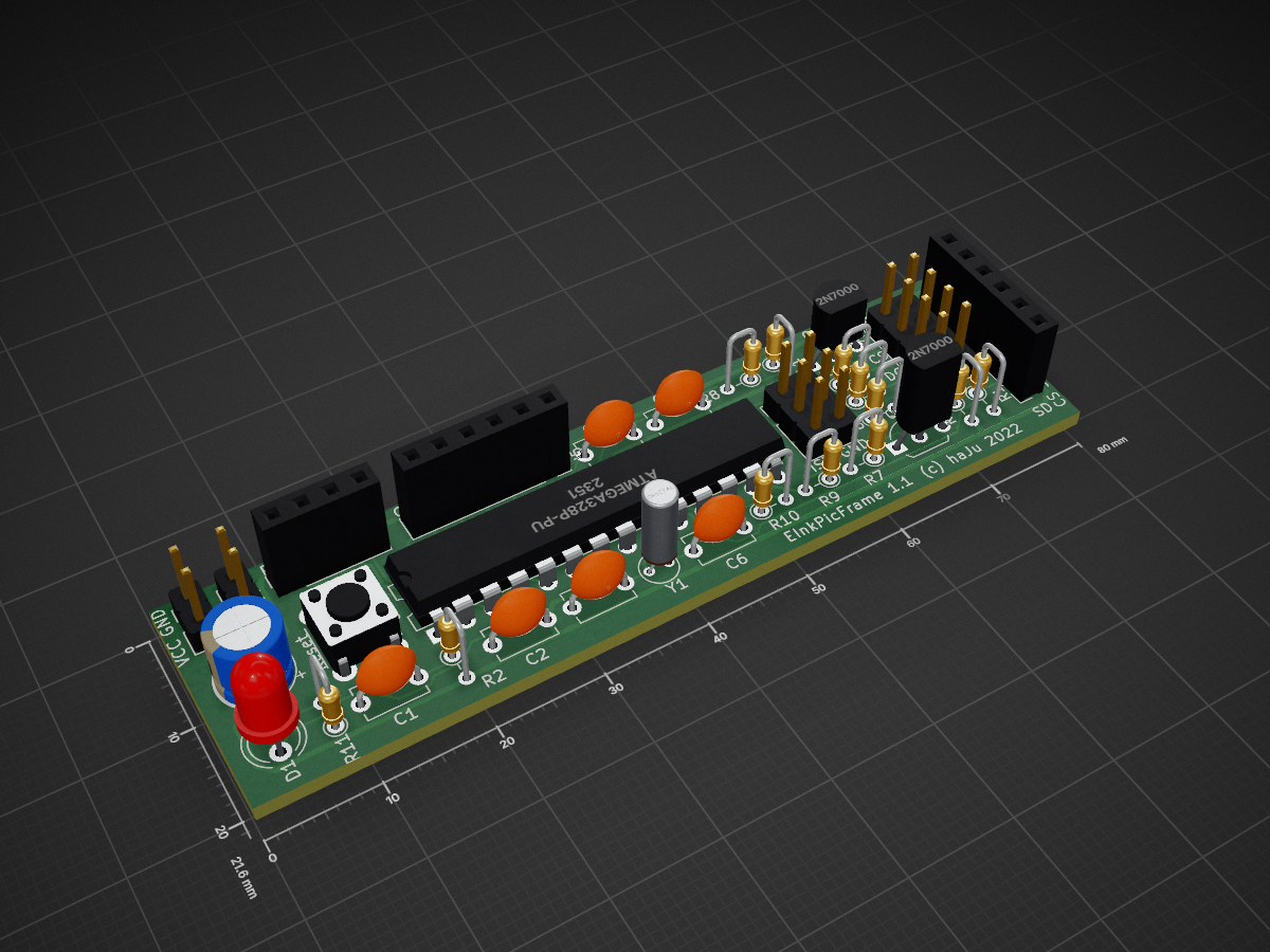
 nhjschulz/EInkPicFrame2
Battery powered picture frame using color E-Ink display
EInkPicFrame is an open-source printed circuit board by nhjschulz, from the nhjschulz/EInkPicFrame repository on GitHub, published under the BSD-3-Clause licence. It is a 2-layer board of 80 × 21.6 mm with 33 parts on 36 nets, routed with 226 tracks and 0 vias.
It is built around the ATMEGA328P-PU. Its parts include 11 resistors, 7 capacitors, 6 connectors, 2 transistors and 1 IC. It belongs with the lEDs and displays and power boards and the AVR (ATmega, ATtiny) boards of this library.
The project builds an electronic picture frame using a 7 color E-Ink display. It updates after an adjustable time period by reading images from an SD-Card. The frame is powered from a battery and mimics a real picture frame by requiring no power cable or a backlight. The software and hardware implements various power saving methods to run for a long time without recharging.
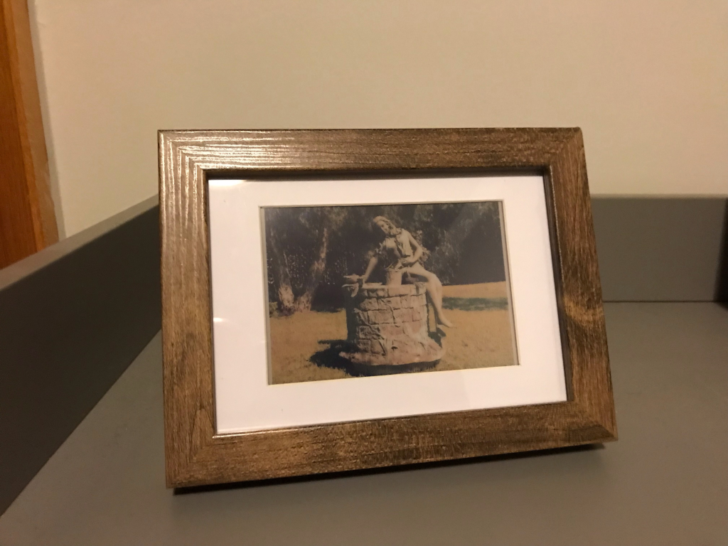
This is a hobbyist project. I have >20 years background in software development, but lack the electronic engineering background. I'm using this project to clear the fog in these mysterious regions below a HAL software layer. The project therefore includes a hardware design as well.
A set of project requirements is collected here: Requirements
Block diagram of the system:
The project is build using open source tools only. All of them are available for free. The following table shows the tools and versions used during development:
| Tool | Usage | Version | Link |
|---|---|---|---|
| Visual Studio Code | Editor and IDE | 1.63.2 | https://code.visualstudio.com/ |
| PlatformIO | Software build tools | 5.2.4 | https://platformio.org/ |
| Python | Script programming | 3.10.1 | https://www.python.org/ |
| GIMP | Image Manipulation | 2.10.30 | https://www.gimp.org/ |
| ImageMagick | Image Manipulation | 7.1.0 | https://imagemagick.org/ |
| GIT | Version Control | 2.19 | https://git-scm.com/ |
| KiCad EDA | Hardware Design | 5.1.12 | https://www.kicad.org// |
The implemented software architecture design is shown on the Software Architecture page.
The system is assembled using the following parts: Partlist.
A description of the PCB developed for this project is described here: PCB.
The images to show on the frame must be in a special raw format. The process to generate this format is described on the ImageConverter page.
The SD Card must be formated using a FAT file system. The software expects a folder with the name "epd" on it. This folder contains the following data:
  [epd]
   |---- [err]
   |---- [img]
|---- epd.cfgAn example file system can be copied from the example File System folder.
2021-12-11: System functional on breadboard (V1 hardware)
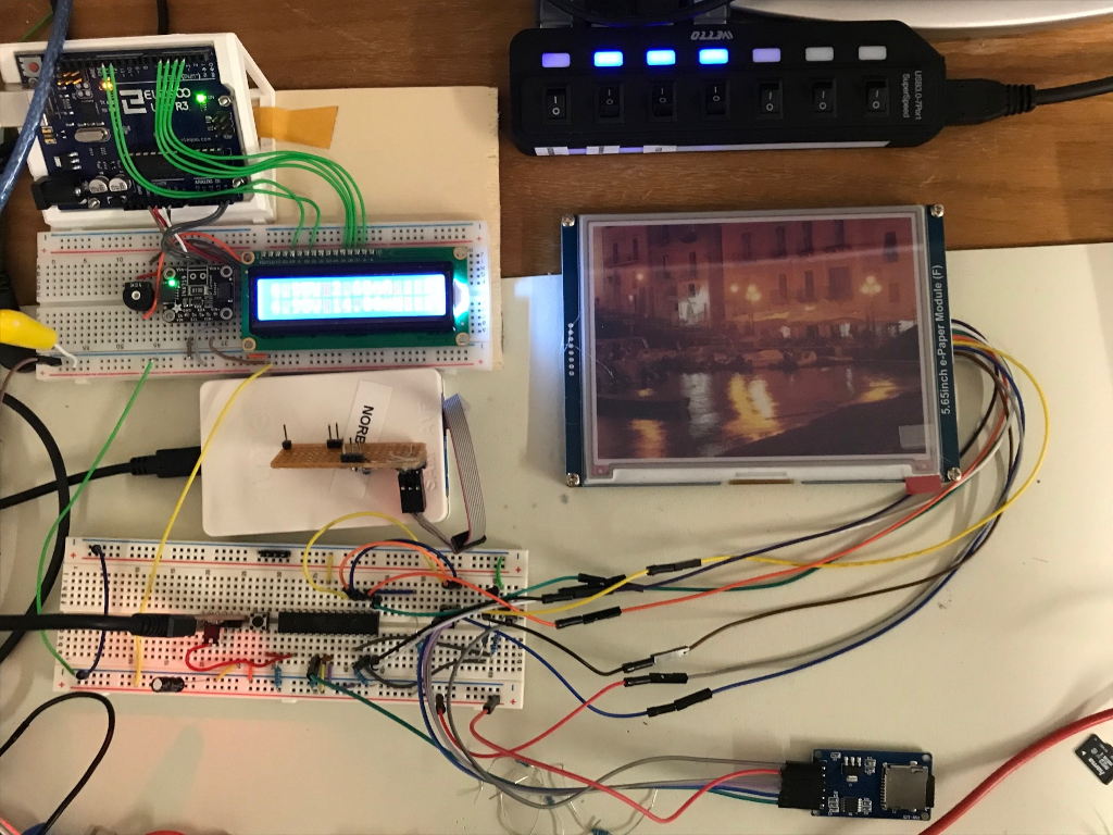
2021-01-22: V1 PCBs arrived and work
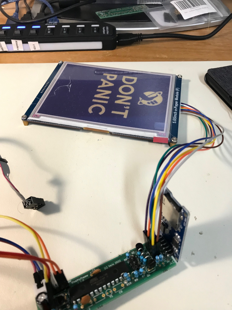
2022-02-01: First frame starts long run test in the living room
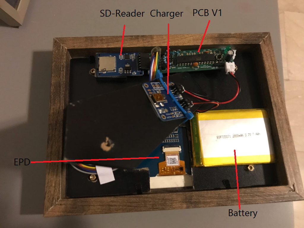
Back side:
| Qty | Value | Footprint | References |
|---|---|---|---|
| 4 | 1M | Resistor_THT:R_Axial_DIN0204_L3.6mm_D1.6mm_P2.54mm_Vertical | R1, R3, R9, R10 |
| 4 | 330 | Resistor_THT:R_Axial_DIN0204_L3.6mm_D1.6mm_P2.54mm_Vertical | R4, R5, R6, R11 |
| 3 | 0.1 uF | Capacitor_THT:C_Disc_D5.1mm_W3.2mm_P5.00mm | C2, C7, C8 |
| 2 | 180 | Resistor_THT:R_Axial_DIN0204_L3.6mm_D1.6mm_P2.54mm_Vertical | R7, R8 |
| 2 | 22 pF | Capacitor_THT:C_Disc_D5.1mm_W3.2mm_P5.00mm | C5, C6 |
| 1 | 10 uH | Resistor_THT:R_Axial_DIN0204_L3.6mm_D1.6mm_P2.54mm_Vertical | L1 |
| 1 | 100 nF | Capacitor_THT:C_Disc_D5.1mm_W3.2mm_P5.00mm | C1 |
| 1 | 10K | Resistor_THT:R_Axial_DIN0204_L3.6mm_D1.6mm_P2.54mm_Vertical | R2 |
| 1 | 2N7000 | Package_TO_SOT_THT:TO-92L_Inline_Wide | Q1 |
| 1 | 2N7000 | Package_TO_SOT_THT:TO-92_Inline_Wide | Q2 |
| 1 | ATmega328P-PU | Package_DIP:DIP-28_W7.62mm | U1 |
| 1 | AVR-ISP-6 | Connector_PinHeader_2.54mm:PinHeader_2x03_P2.54mm_Vertical | J2 |
| 1 | CP | Capacitor_THT:CP_Radial_D6.3mm_P2.50mm | C3 |
| 1 | Crystal | Crystal:Crystal_C38-LF_D3.0mm_L8.0mm_Vertical | Y1 |
| 1 | Debug | Connector_PinSocket_2.54mm:PinSocket_1x04_P2.54mm_Vertical | J7 |
| 1 | EPD | Connector_PinHeader_2.54mm:PinHeader_2x04_P2.54mm_Vertical | J3 |
| 1 | Jumper | Connector_PinHeader_2.54mm:PinHeader_1x02_P2.54mm_Vertical | JP1 |
| 1 | LED | LED_THT:LED_D4.0mm | D1 |
| 1 | PORTC | Connector_PinSocket_2.54mm:PinSocket_1x06_P2.54mm_Vertical | J5 |
| 1 | Power | Connector_PinHeader_2.54mm:PinHeader_1x02_P2.54mm_Vertical | J4 |
| 1 | SD | Connector_PinSocket_2.54mm:PinSocket_1x06_P2.54mm_Vertical | J1 |
| 1 | SW_Push | Button_Switch_THT:SW_PUSH_6mm | SW1 |
The 32 most common of 33 parts.
It measures 80 × 21.6 mm and has 2 copper layers, 1.6 mm thick.
33 parts, built around the ATMEGA328P-PU. The full list of its parts is on this page, with links to each part's symbol and footprint where PCBKit's library has them.
From the nhjschulz/EInkPicFrame repository on GitHub, at the commit this page was made from: the board is hw/EinkPicFrame.kicad_pcb. PCBKit opens the board in the browser, with nothing to install.
Its repository publishes it under the BSD-3-Clause licence: you may reuse it on that licence's terms (keep the author's notice, and for a copyleft licence share your changes alike).
zmaker/arduino_cookbook
gli sketch del nuovo progetto Arduino Cookbook e dei video di YouTube

coseyfannitutti/discipad
17-key numpad assembled with only through hole components, including usb type-c

matthewcieplak/super-sixteen
Code and schematics for the Super Sixteen Eurorack sequencer

coseyfannitutti/romeo
Staggered 40% keyboard pcb that can be assembled with only through hole components, including USB Type-C

mattybrad/drumkid
Version 4 was the first successful working design, with full code, schematics, Gerbers, etc available on GitHub.


leomil72/LM80C
A Z80-based homebrew computer withTMS9918, AY-3-8910, Z80 CTC, Z80 PIO, and Z80 SIO
