2 layers30.5 × 76.2 mm
Headfour
nezumee/4x4
The 4x4 keyboard is a modular keyboard with per-key RGB lighting intended to be used as a base for prototyping MIDI controller with QMK firmware.
15 parts21MIT

 nezumee/4x421
The 4x4 keyboard is a modular keyboard with per-key RGB lighting intended to be used as a base for prototyping MIDI controller with QMK firmware.
Fourbyfour is an open-source printed circuit board by nezumee, from the nezumee/4x4 repository on GitHub, published under the MIT licence. It is a 2-layer board of 76.2 × 76.2 mm with 64 parts on 55 nets, routed with 1,501 tracks and 99 vias.
Its parts include 32 diodes and 16 switches.
The 4x4 keyboard is a modular keyboard with per-key RGB lighting intended to be used as a base for prototyping MIDI controller with QMK firmware.
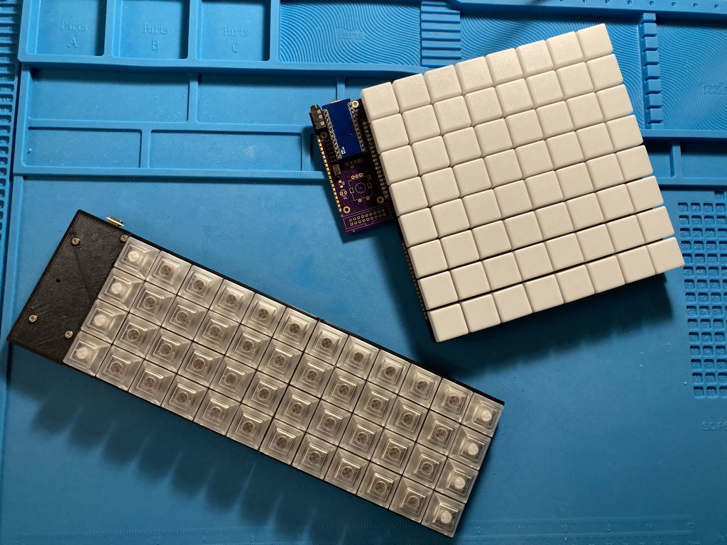
It consists of the following parts:
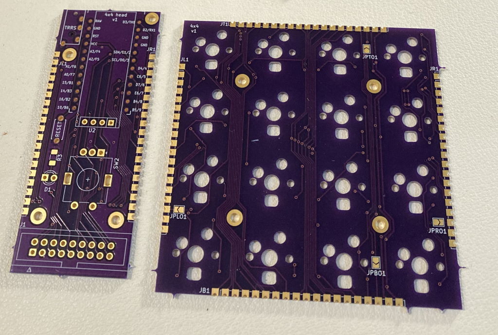
These parts can be soldered together in different configurations, resulting in different layouts, such as 4x12 Planck layout or 8x8 layout similar to MIDI drumpads controllers.
The modular design allows to iterate on parts of it without remaking a large PCB. It also makes it cost-effective to order from PCB prototyping service - ordering the typical minimum of 3 to 5 pieces of key PCB makes a single full-sized keyboard with no excessive number of spares.
PCB pieces use castellated pads to route all the signals. These pads are soldered together placing the PCBs side by side, connecting them electrically and also holding them together physically.
To allow for modularity and avoid using lots of wires to connect parts together, electrical layout of the key PCBs doesn't match their physical layout. Even though physically they are 4x4, electrically switches are laid out in 2 columns and 8 rows:
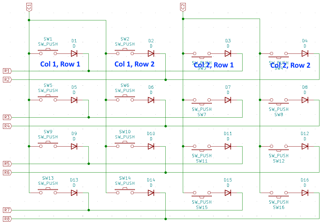 Each key module uses the same row wires but separate columns so the full electrical layout is 8x8 if there are 4 key modules.
The column lines are routed through the key PCBs such that columns are shifted in the next connected module: if a key module is directly connected to the head, it will connect to columns 1 and 2. Module attached to the right of it will use columns 3 and 4, and so on. Attaching a module to the bottom of another shifts columns by 4 instead. The end result is that in all supported configurations, simply soldering the key modules together in the desired layout gives each of them a unique pair of column wires connected to the MCU.
Row lines are not shifted, they are passed through across the key modules as is and connect to the same MCU pin in every module.
WS6812 mini-e LEDs are used to provide per-key RGB. These LEDs require that they are connected in a chain to let the signal propagate from one LED to another. Within each key module, they are connected like this: 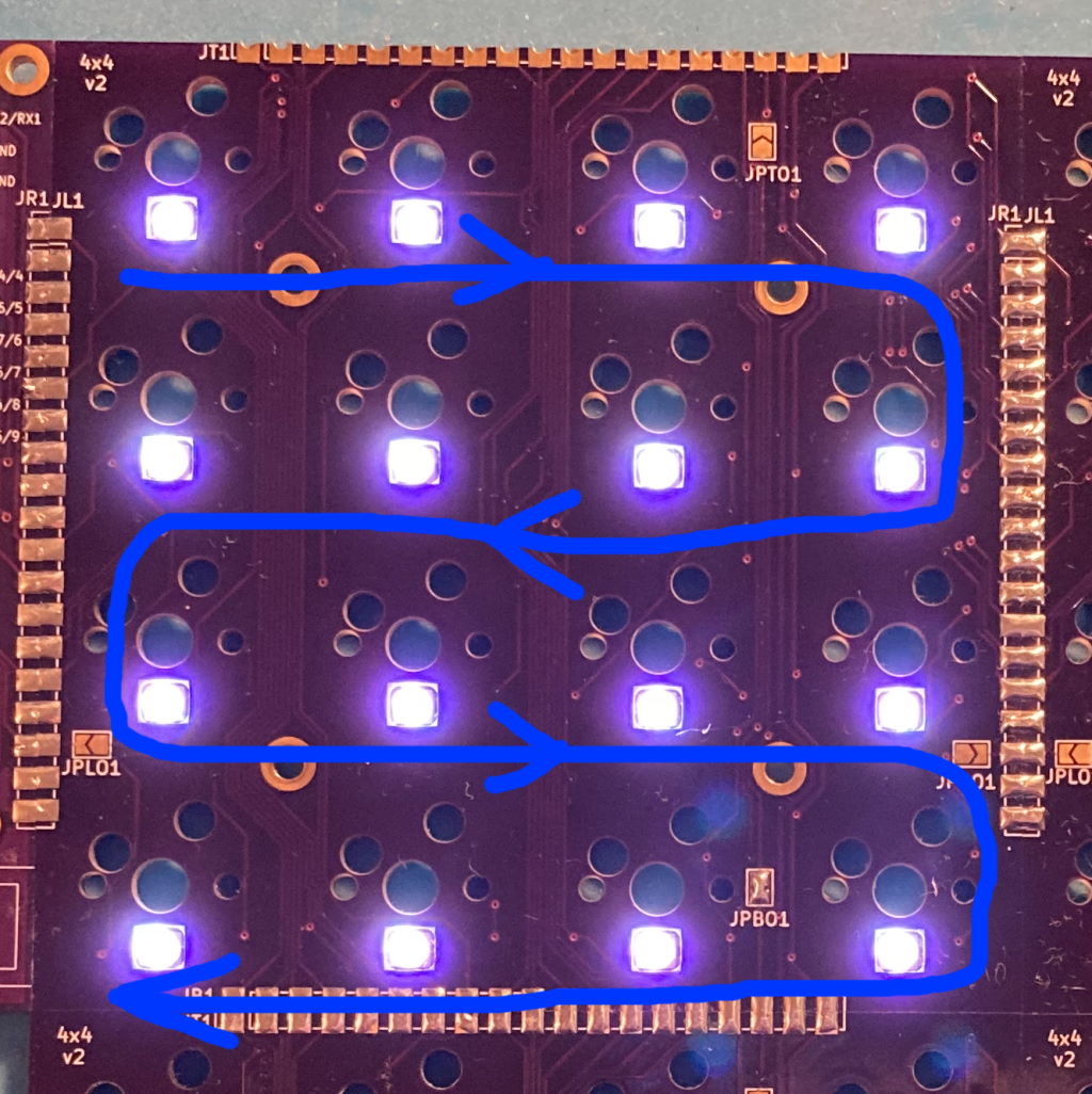
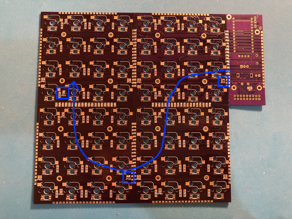
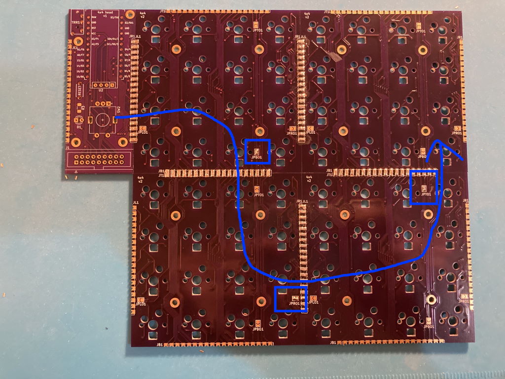
To connect them across key modules, jumpers need to be soldered on each module to specify the side that takes LED input from previous module in the chain, and the side connecting to the next module:
This builds a chain of key modules, connecting the last LED in the preceding module to the first LED in the next:
| Item | Quantity | Comment | Source |
|---|---|---|---|
| Head PCB | 1 | KiCad source | gerber |
| Key PCBs | 1-4 | KiCad source | gerber |
| ProMicro MCU | 1 | ||
| MCU socket | 1 | 2 strips of 12 pins each | https://www.digikey.com/en/products/detail/mill-max-manufacturing-corp/310-43-112-41-001000/1212186 |
| Reset tactile button | 1 | ||
| TRRS jack | 1 | To support split keyboard, optional | https://boardsource.xyz/store/5eca3b7d64caf04f83aa6488 |
| Kailh MX hotswap sockets | 16-64 | https://boardsource.xyz/store/5eca066464caf04f83aa647f | |
| N4148 SOD-123 diodes | 16-64 | https://www.digikey.com/en/products/detail/panjit-international-inc/1N4148W-R1-00001/14660400 | |
| SK6812 mini-e RGB LEDs | 16-64 | Optional | https://boardsource.xyz/store/5f6316e0a2c1b43e37ca04c3 |
| Cherry MX compatible switches, keycaps | 16-64 | ||
| Switch plate, case | Optional | See some example designs here | |
| M2 bolts and standoffs | 8-20 |
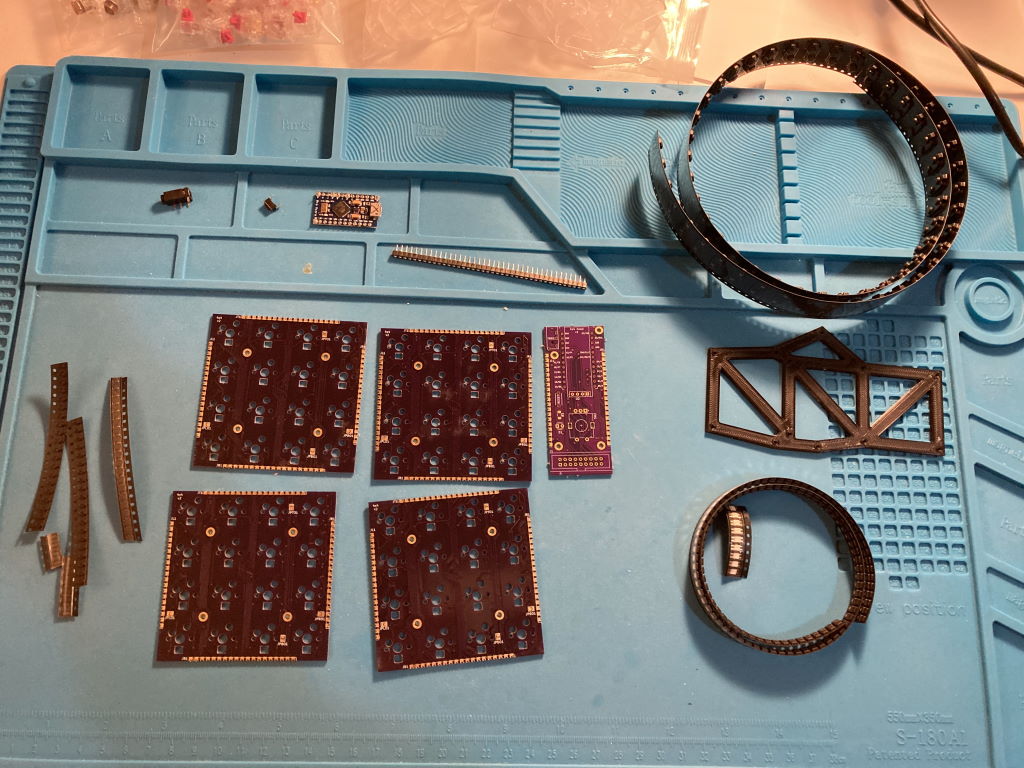
Decide on the layout
Prep the PCBs
Solder together the PCBs pieces
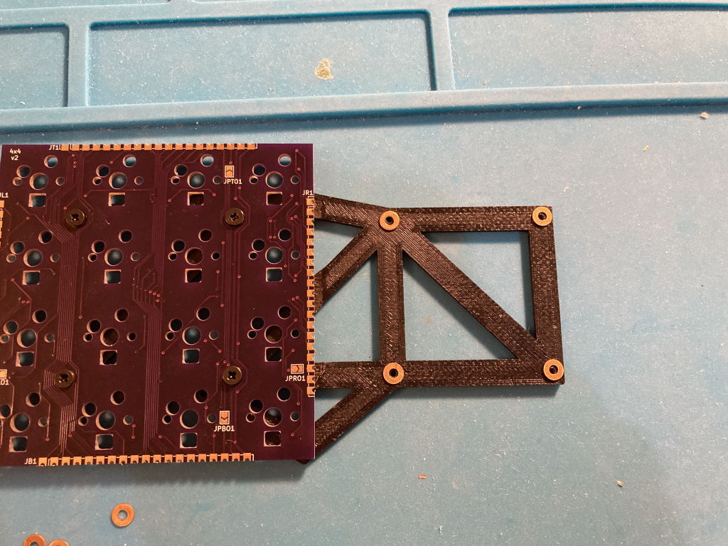
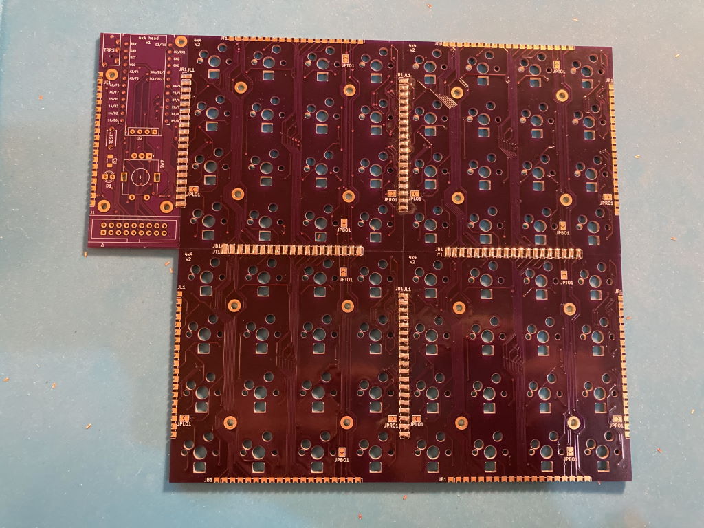
Solder the jumpers for LED signal chaining
Solder the MCU socket so that you can test the rest as you go
Solder the per-key elements
Solder the remaining head elements
End result:
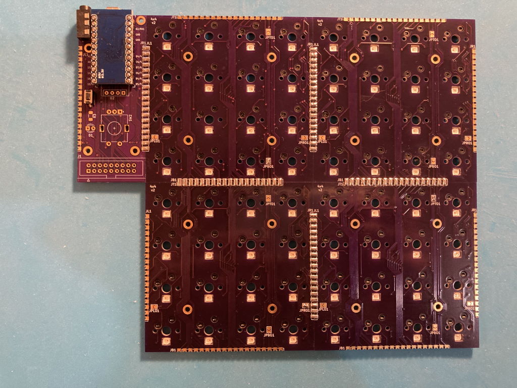
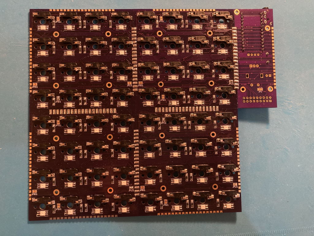
This keyboard is using QMK. Example layout making the keyboard work as a combination of planck keyboard and a MIDI controller is available here. Note that you need the MIDI input fix for the MIDI feedback to work.
QMK has MIDI support that allows using the keyboard as a MIDI controller. Per-key RGB also makes it possible to have MIDI feedback, such that each key lights up depending on the status in the DAW. For example, you can set it up that keyboard keys trigger clips or scenes, and have those keys light up in the right color when there's an active clip or when a track is armed for recording.
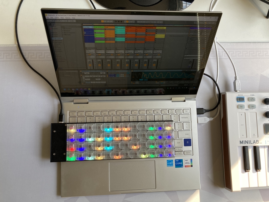
This support requires some integration in the DAW. Remote MIDI script for Ableton Live working with the Planck-like layout is here.
This project is using the MIT license.
| Qty | Value | Footprint | References |
|---|---|---|---|
| 16 | D | kbd:D3_SMD_v2 | D1, D2, D3, D4, D5, D6, D7, D8, D9, D10, D11, D12, D13, D14, D15, D16 |
| 16 | SW_PUSH | fourbyfour:CherryMX_Hotswap | SW1, SW2, SW3, SW4, SW5, SW6, SW7, SW8, SW9, SW10, SW11, SW12, SW13, SW14, SW15, SW16 |
| 16 | YS-SK6812MINI-E | fourbyfour:YS-SK6812MINI-E | LED1, LED2, LED3, LED4, LED5, LED6, LED7, LED8, LED9, LED10, LED11, LED12, LED13, LED14, LED15, LED16 |
| 8 | SolderJumper_2_Open | Jumper:SolderJumper-2_P1.3mm_Open_TrianglePad1.0x1.5mm | JPBI1, JPBO1, JPLI1, JPLO1, JPRI1, JPRO1, JPTI1, JPTO1 |
| 2 | Conn_01x19 | fourbyfour:PinHeader_1x19_P2.54mm_CastellatedR | JB1, JL1 |
| 2 | Conn_01x19 | fourbyfour:PinHeader_1x19_P2.54mm_CastellatedL | JR1, JT1 |
The 60 most common of 64 parts.
nezumee/4x4
The 4x4 keyboard is a modular keyboard with per-key RGB lighting intended to be used as a base for prototyping MIDI controller with QMK firmware.

hackclub/OnBoard
💡 Join 1,000 teenagers and make your first PCB with a $100 grant!

drandyhaas/KiCadRoutingTools
A set of Python/Rust tools to aid routing in KiCad

BlueSCSI/BlueSCSI-v2
BlueSCSI v2/Ultra - an open source, open hardware, SCSI emulator using the Pi Pico PR2040 and Pico 2 RP2350


PyrooL/Alpha
A 28-key semi-ortholinear mechanical keyboard designed by PyroL

ugcs/ddc
Drone Show Software is software designed for drone shows, allowing flight path planning as well as control of dozens of drones simultaneously in a synchronized manner.

It measures 76.2 × 76.2 mm and has 2 copper layers, 1.6 mm thick.
64 parts. The full list of its parts is on this page, with links to each part's symbol and footprint where PCBKit's library has them.
From the nezumee/4x4 repository on GitHub, at the commit this page was made from: the board is pcb/fourbyfour/fourbyfour.kicad_pcb. PCBKit opens the board in the browser, with nothing to install.
Its repository publishes it under the MIT licence: you may reuse it on that licence's terms (keep the author's notice, and for a copyleft licence share your changes alike).