2 layers50 × 35 mm

 NetRunSecurity/BusinessCardUSB9
BusinessCard USB - CH552G
Business card proto is an open-source printed circuit board by NetRunSecurity, from the NetRunSecurity/BusinessCardUSB repository on GitHub. It is a 2-layer board of 86.4 × 54 mm with 17 parts on 20 nets, routed with 154 tracks and 24 vias.
Its parts include 4 resistors, 3 capacitors, 2 ICs, 2 switches and 1 diode. It belongs with the interfaces and adapters boards of this library.
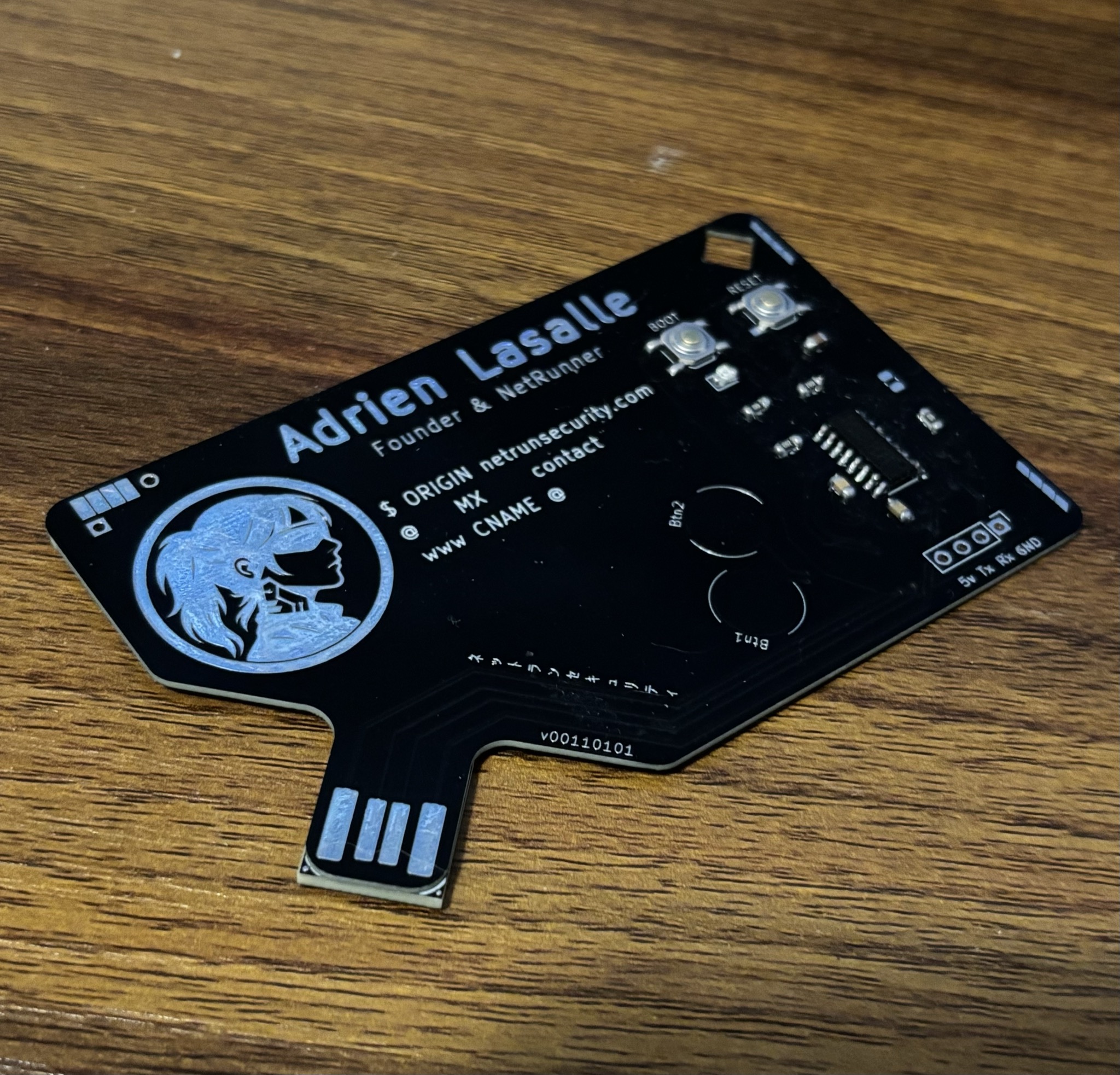
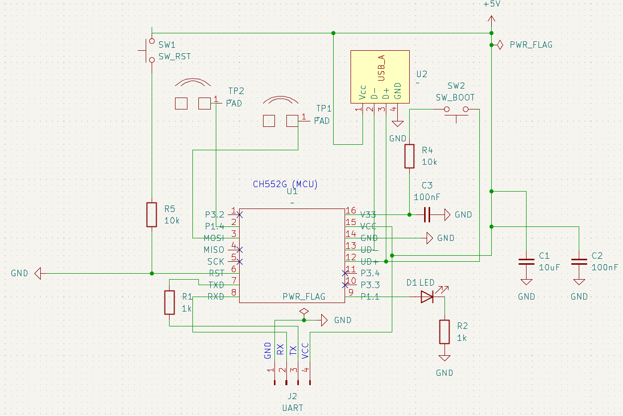
A real, working USB business card. It's shaped like a card, but the bottom edge is cut into a USB-A male connector, plug it straight into any port, no cable, no adapter. Powered by a CH552G with native USB (no USB-to-serial bridge chip), two capacitive touch pads, a status LED, and a UART debug header.
It's a business card, a hacking tool, and a flex in one.
📖 Full build write-up, schematics and pinout: https://wiki.netrunsecurity.com/electronics/sao/business-card/
.
├─ hardware/
│  ├─ card/
│  │  ├─ v4/          # current editable KiCad design (source of truth)
│  │  └─ v3/          # validated production build, gerbers only
│  └─ shim/           # USB-tab PCB shim (KiCad source + gerbers)
├─ firmware/
│  ├─ rubber-ducky/   # HID keystroke injection (opens a URL on plug-in)
│  ├─ touchpad-testing/ # capacitive Touch-Key + LED demo
│  ├─ ctf/            # USB serial CLI with hidden flags
│  └─ usb-uart-bridge/ # USB ↔ UART bridge for debugging IoT targets
├─ docs/              # photos, schematic PDF, fabrication files (BOM)
├─ LICENSE            # TAPR OHL 1.0, hardware
└─ firmware/LICENSE # GPL-3.0, firmware| Version | Status | Files |
|---|---|---|
| V3 | Soldered & tested, the build in the photos | Gerbers (archived) |
| V4 | Same circuit, current revision | Full KiCad sources |
V3 and V4 are electrically identical. R6 was a redundant RST pull-down (R5 already pulls RST to VCC) and was left unpopulated on V3, so it never affected the circuit. V4 removes the footprint to prevent accidental population and updates the silkscreen text. The V4 sources faithfully represent the validated V3 build.
⚠️ The original
v00110100board had a reversed USB edge-connector polarity that destroyed chips on plug-in. Do not fabricate that revision. Use V3/V4.
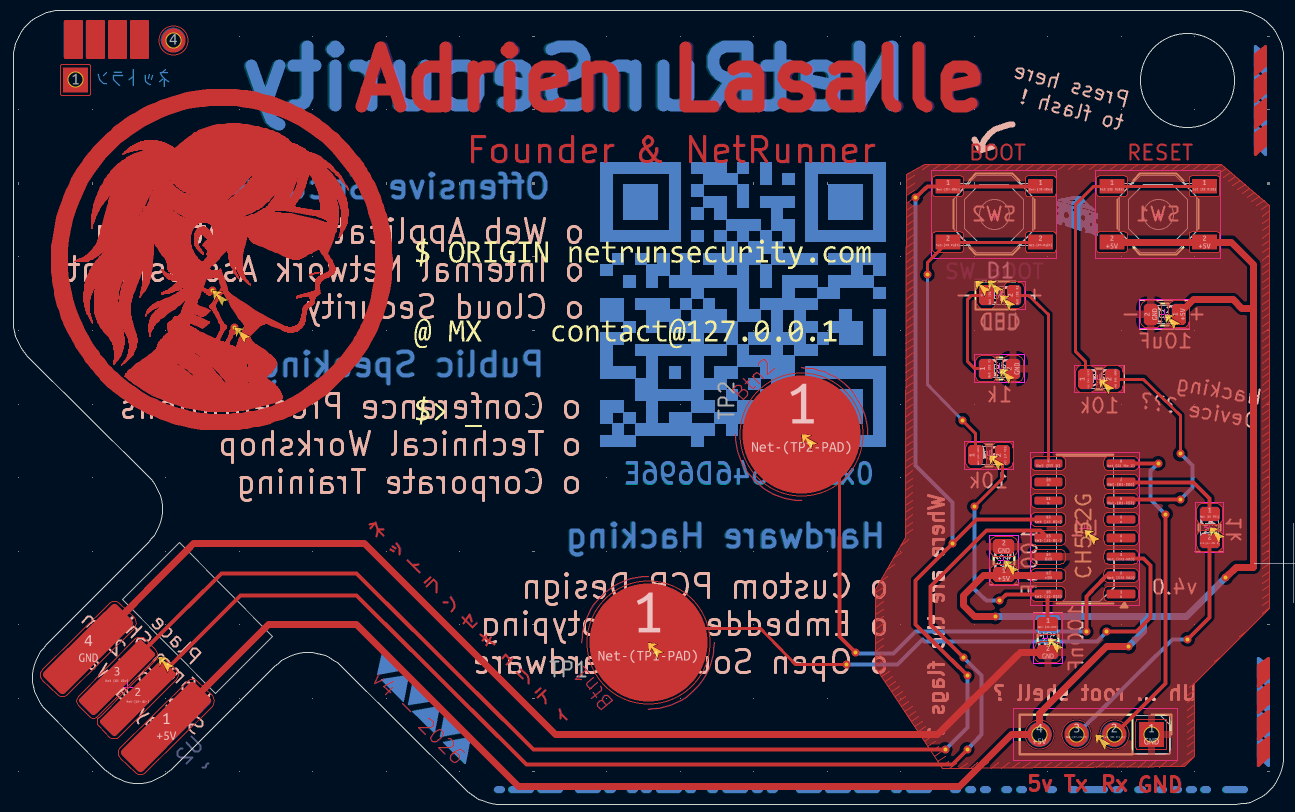
| Ref | Qty | Value / Part | Package | MPN | LCSC |
|---|---|---|---|---|---|
| U1 | 1 | CH552G — 8-bit USB MCU | SOP-16 | CH552G | C111292 |
| C1 | 1 | 10 µF 16 V X5R | 0805 | CL21A106KOQNNNE | C1713 |
| C2, C3 | 2 | 100 nF 50 V X7R | 0805 | CC0805KRX7R9BB104 | C49678 |
| R1, R2 | 2 | 1 kΩ 1% | 0805 | 0805W8F1001T5E | C17513 |
| R4, R5 | 2 | 10 kΩ 1% | 0805 | 0805W8F1002T5E | C17414 |
| D1 | 1 | Red LED 630 nm | 0805 | NCD0805R1 | C84256 |
| SW1, SW2 | 2 | Tactile switch SPST | SMD 5.2×5.2 mm | TL3342F260QG | C2886894 |
| J2 | 1 | 1×4 pin header 2.54 mm (UART) | THT | HX PH254-01-04 | C52016392 |
R6 is not populated (removed in V4). TP1/TP2 are copper touch pads and U2 is the PCB-edge USB connector — neither is a placed part.
Several firmwares, each demoing a different capability of the platform:
Build & flash instructions are in firmware/README.md
(Arduino IDE 2.x + ch55xduino).
hardware/card/v4/ (or v3/) to any fab.docs/ (LCSC part numbers included).firmware/README.md.A few hard-won notes: hand-solder the SOP-16 (no hot air), verify USB edge-pad polarity against the socket before ordering, and keep a USB power meter handy for first power-up.
This is open hardware, dual-licensed:
LICENSE.firmware/LICENSE.Derivatives welcome, credit the original and highlight your changes.
Designed by AlrikRr, NetRunSecurity · wiki · linktr.ee
| Qty | Value | Footprint | References |
|---|---|---|---|
| 2 | , | ||
| 2 | 100nF | Capacitor_SMD:C_0805_2012Metric | C2, C3 |
| 2 | 10k | Resistor_SMD:R_0805_2012Metric | R4, R5 |
| 2 | 1k | Resistor_SMD:R_0805_2012Metric | R1, R2 |
| 2 | ~ | NetRun_Library:TouchPad_Circle_10mm | TP1, TP2 |
| 1 | 10uF | Capacitor_SMD:C_0805_2012Metric | C1 |
| 1 | LED | LED_SMD:LED_0805_2012Metric | D1 |
| 1 | SW_BOOT | Button_Switch_SMD:SW_SPST_TL3342 | SW2 |
| 1 | SW_RST | Button_Switch_SMD:SW_SPST_TL3342 | SW1 |
| 1 | UART | Connector_PinHeader_2.54mm:PinHeader_1x04_P2.54mm_Vertical | J2 |
| 1 | ~ | Package_SO:SOIC-16_3.9x9.9mm_P1.27mm | U1 |
| 1 | ~ | NetRun_Library:PCB_USB | U2 |
It measures 86.4 × 54 mm and has 2 copper layers, 1.6 mm thick.
17 parts. The full list of its parts is on this page, with links to each part's symbol and footprint where PCBKit's library has them.
From the NetRunSecurity/BusinessCardUSB repository on GitHub, at the commit this page was made from: the board is hardware/card/v4/Business-card-proto.kicad_pcb and its schematic hardware/card/v4/Business-card-proto.kicad_sch. PCBKit opens the board in the browser, with nothing to install.
Its repository states no licence, so its author keeps all rights: ask NetRunSecurity before reusing the design.


hoglet67/RGBtoHDMI
Bare-metal Raspberry Pi project that provides pixel-perfect sampling of Retro Computer RGB/YUV video and conversion to HDMI


hackclub/OnBoard
💡 Join 1,000 teenagers and make your first PCB with a $100 grant!

DDeGonge/OS-ARM
This arm is not industrial and it will not be fast, but that is not my goal. But it will hopefully be a very nice looking arm fully capable of 6dof motion, cheap enough to keep it accessable but capable enough to…

