4 layers25 × 35 mm
Qfn csi underpad diff
drandyhaas/KiCadRoutingTools
A set of Python/Rust tools to aid routing in KiCad
2 parts744MIT

 nejc-cc/hexaled29
Hexagon ceiling lights
HexLED is an open-source printed circuit board by nejc-cc, from the nejc-cc/hexaled repository on GitHub. It is a 4-layer board of 19.6 × 25.1 mm with 2 parts on 3 nets.
Modular hexagon ceiling lights using 24 V CCT COB LED strips
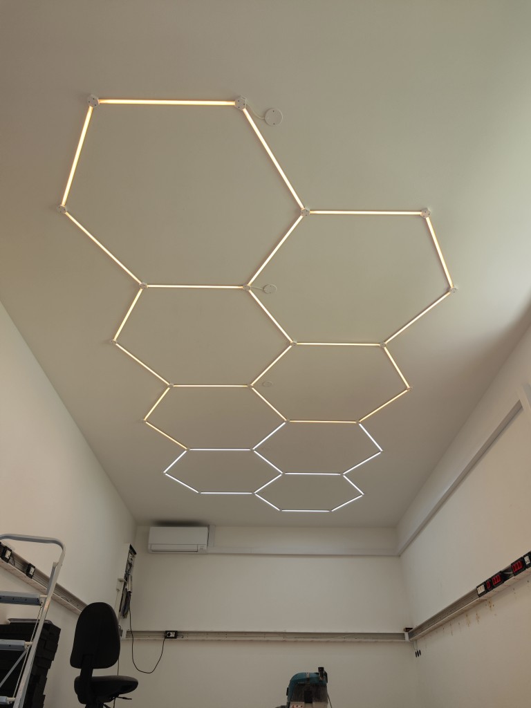
I saw many of these "Hexagon LED" ceiling lights but none that would fit my needs:
After about 5 days worth of walking up and down my ladder, a lot of cutting and stripping wires, even more soldering and eventually figuring out I messed up the lengths again... I somehow made it!
I won't go in too many details why I made some decisions because that would take too long but trust me, be precise when cutting wires and mounting everything. This project is made so (poorly?) that it only has up to 2 mm tolerance on a segment before you're forced to make some wires longer or shorter or it just won't fit.
I decided to make 5 groups of 7 LED strips so the current is evenly distributed. I'm running them all in 2 groups right now, I'm waiting to get An-Penta-Deca delivered, then I'll be splitting them :)
Here's a list of what measurements are important:
I hope I can explain in enough detail how to make this :)
You need to cut the profiles to 665 mm pieces. Why 665? Well I got the profiles in 2 m lengths and it was the least amount of waste doing it this way.
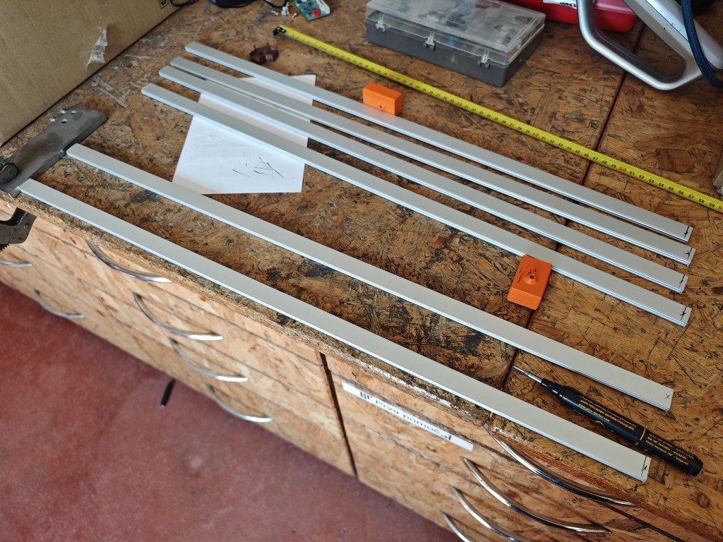
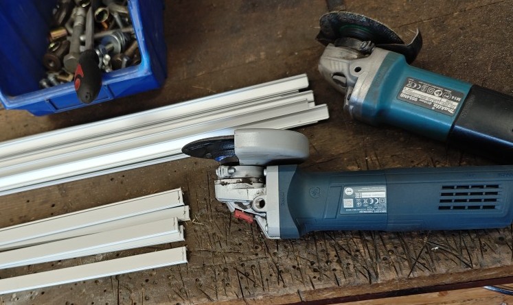
I then went to work with angle grinders. First I cut the profiles then I used the 2nd grinder to round the edges a bit.
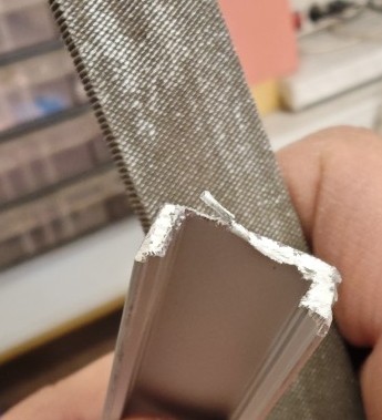
Manual file was used to reach inside parts of profile. I wanted to make all corners smooth, silicone wires are easily damaged!
I used a simple 3D printed jig to drill 3 mm holes in correct spot for all the profiles. Just make sure to clear out the debris every so often. I should've made the jig open from the bottom but.. Too late now :)
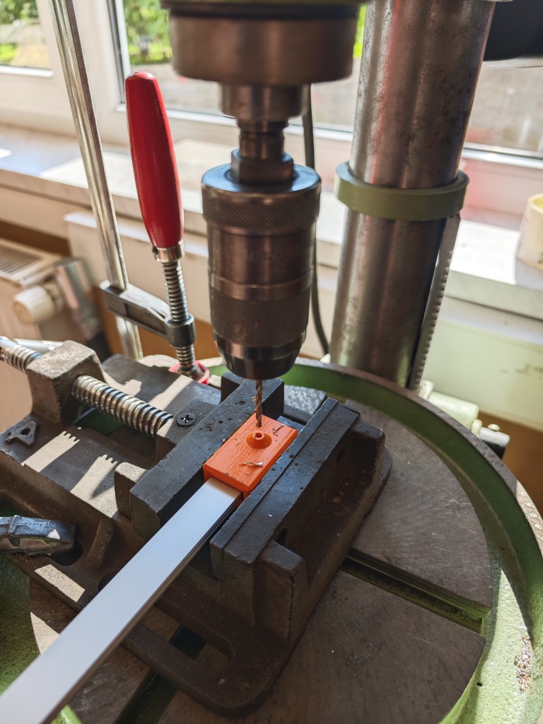
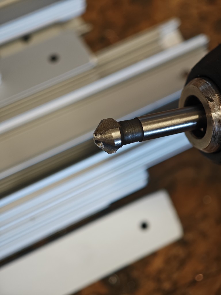
I made sure to have all edges nice and clean with no sharp edges.
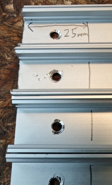
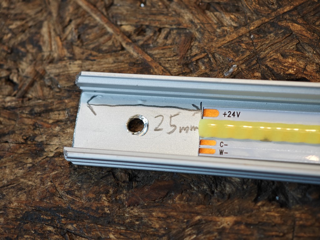
Last step is to mark where the strips need to be placed. Don't hurry or it will bite you later. Ask me how I know. Mark a line 25 mm from edge.
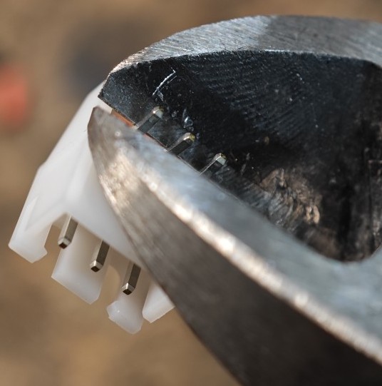
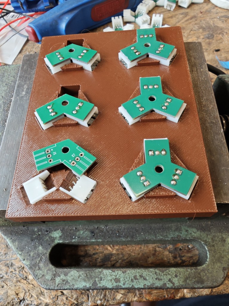
The PCBs are really easy to solder, just keep in mind that you cut the connectors before soldering them!
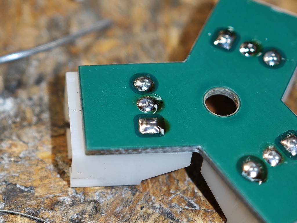
Make sure all the solder joints are as flush as possible, there isn't a lot of free space that we're working with :)
You can use the jig that I also provided.
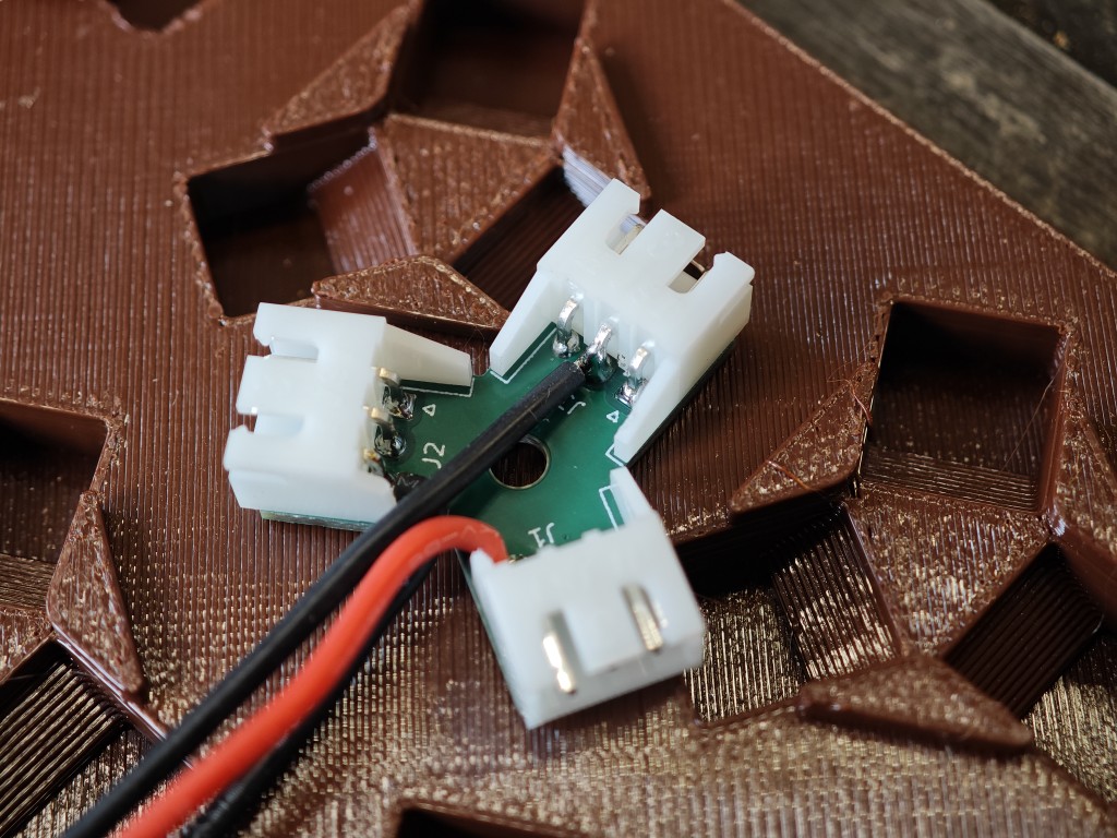
Power injection "nodes" are a bit of a pain in the butt to make, I admit. Note to self: don't ever order PCBs at 1 AM. Sleep it over and order the next morning. I later replaced the wires with longer (and slightly thicker) ones so I could hide them better.
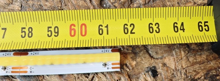
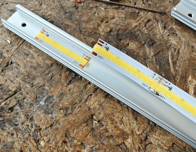
Cut the strips at cut marks, my strips had them at about 616 mm.
Now remove backing foil from the strips and start gluing them to profiles. I found this way to be easier: gluing then soldering cables. I'll explain later why. Make sure to be as precise as possible. I know I will sound like a parrot until the end of this guide.
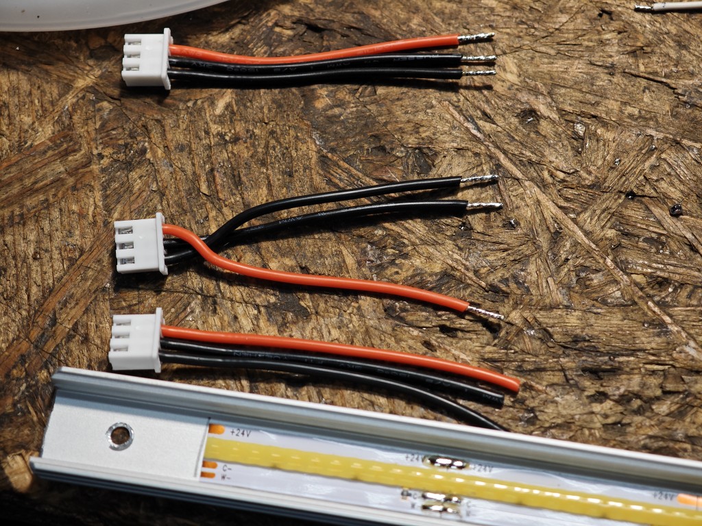
For cutting the cables I found it easiest to just prepare 2 heatshrink tubes that you put over the cables before you cut them. I prepared 1 tube for "shorter" cables (on top of photo) and 1 tube with a notch for the longer cables (bottom 2 cables, one has crossed wires but they are of same length). The short is 54 mm long and the long one is 57 mm long. For the longer cables, make sure to shorten the middle wire by about 2 mm!
It helps to move the wires to the side before soldering them. Make sure all the connectors are facing wrong-side-up. I did it this way to avoid shorting pads on PCB with any kind of screw that would be underneath it. This is the reason the PCBs are also "mounted" wrong side up. Well technically they are mounted the right side up but we're looking at them from bottom :P
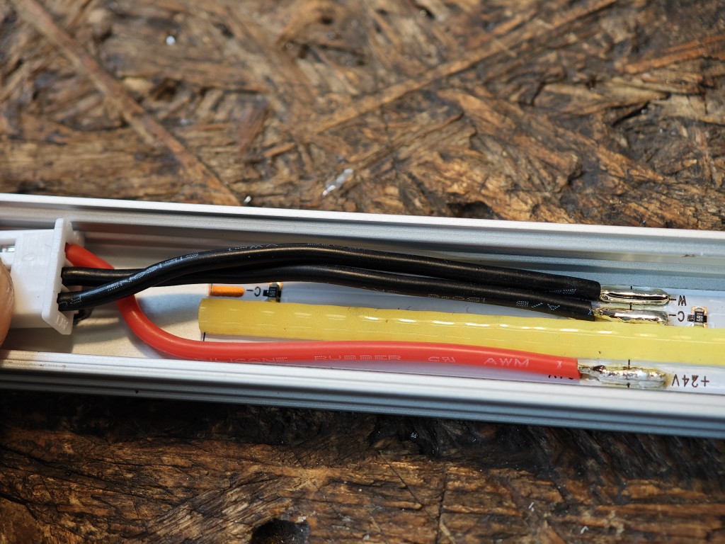
Don't hurry and make sure to check for potential shorts. Luckily I caught this one before I turned everything on. Pro tip: use a multimeter to check for shorts before powering it all on! I know I've stripped the wires too much, I had to move them a bit because I couldn't connect them. Oops :)
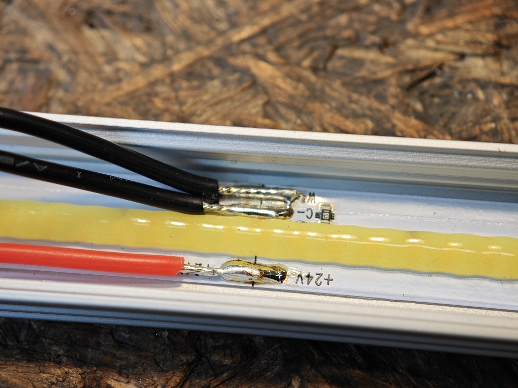
At first it seems like it's taking ages to make it but somehow it was easier the more I made. I didn't even solder all the cables on both ends either, no need to.
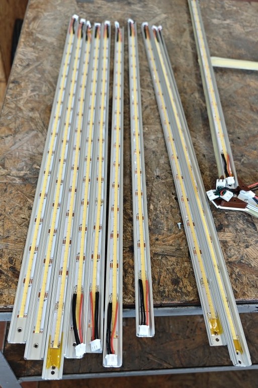
It makes sense to make a plan of how you want to connect the LEDs. I made 5 groups of 7 segments each. This way you can also figure out how many cables you even need to solder and how many V and Y PCBs you need.
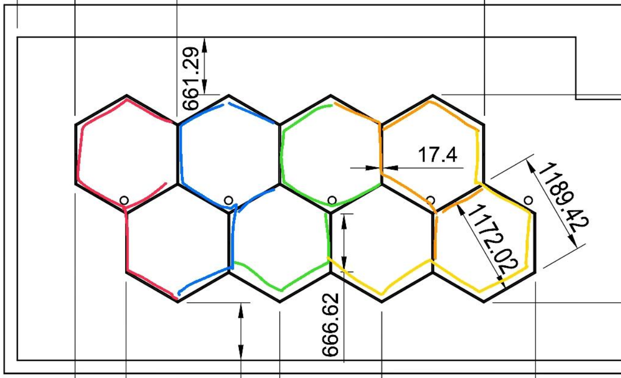
You first need to make some evenly-spaced holes. This was my plan how I wanted it to look like.
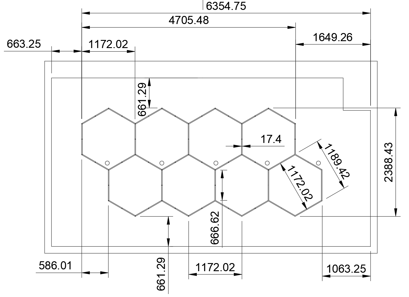
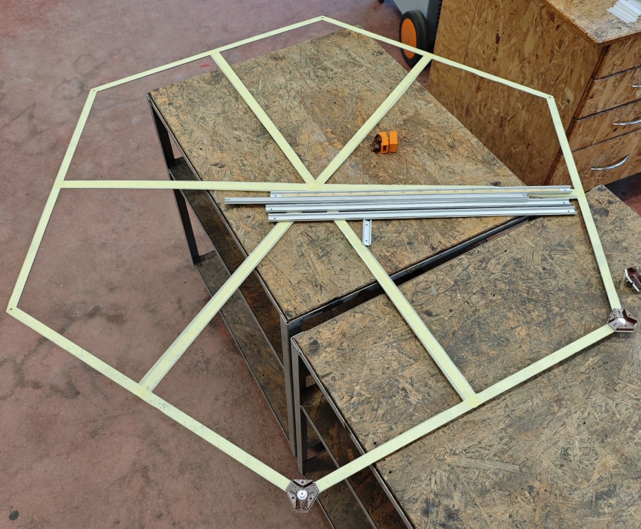
My neighbor has a laser CNC cutter and made me a jig that helped immensely when I was marking holes. I also couldn't do this without my sister. I needed someone to hold it in place while I marked the holes. The first 6 holes were the most critical, if I messed them up, it would skew the whole project. I actually bought a line laser level for this purpose.
My ceiling is made from drywall so I used the anchors that have normal M5 screws. I didn't dare to go with cheaper ones as that would prevent me from being unable to ever remove or replace anything. Not the cheapest solution, i know :/
When mounting the base parts, don't screw them tightly yet, you'll need to turn them to correct orientation first!
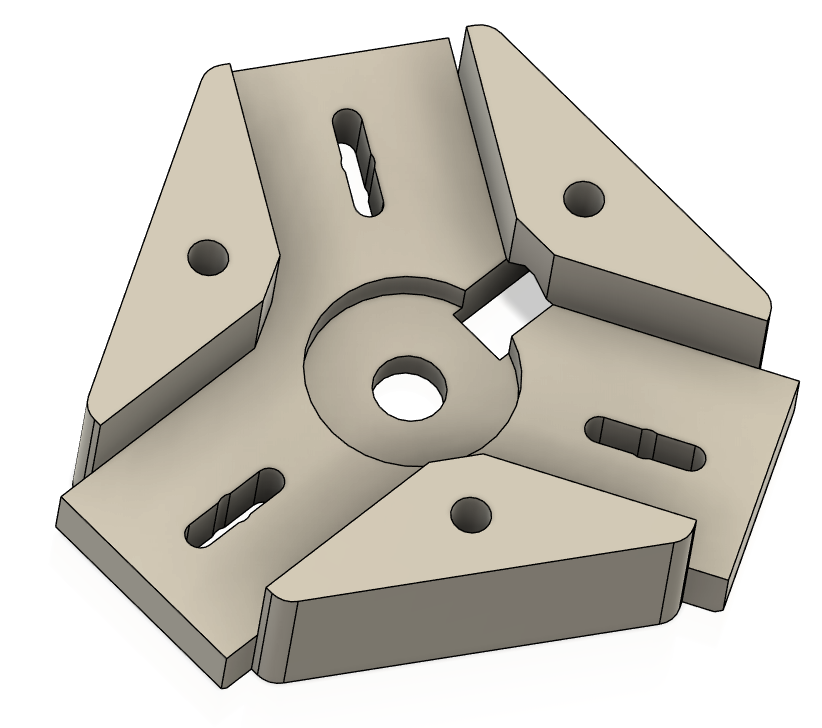
I don't really have photos of whole mounting process but it's pretty straightforward. Space the profiles evenly, use 2 screws for each profile and that's about it.
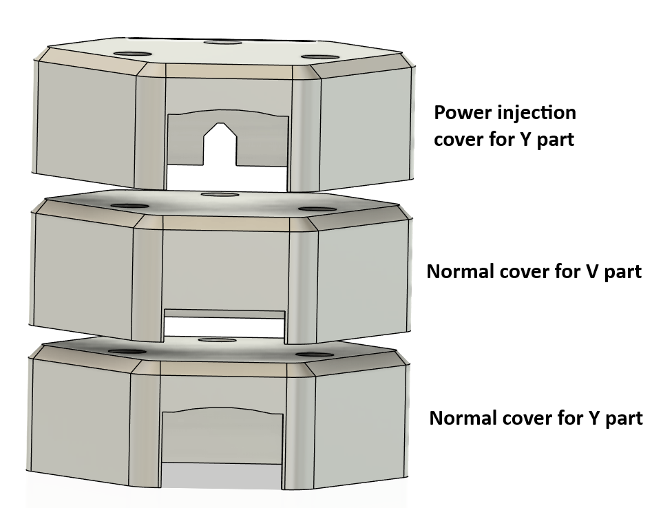
After connecting the Y and V PCBs and tucking in the cables, use the covers/diffusers and covers to hide everything.
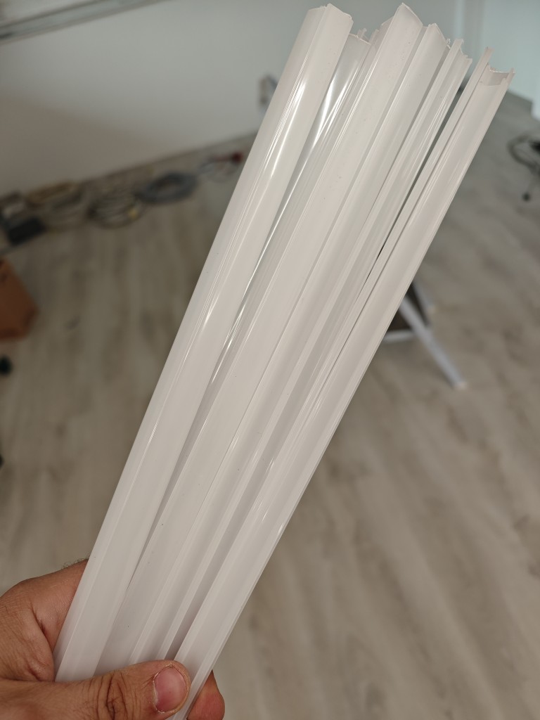
This is why dimensions matter so much. There are a few mm you can cut from diffusers but if you cut more than 3-4 mm, the gap will show.
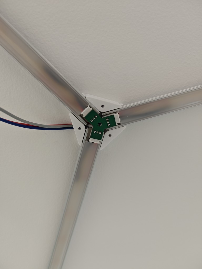
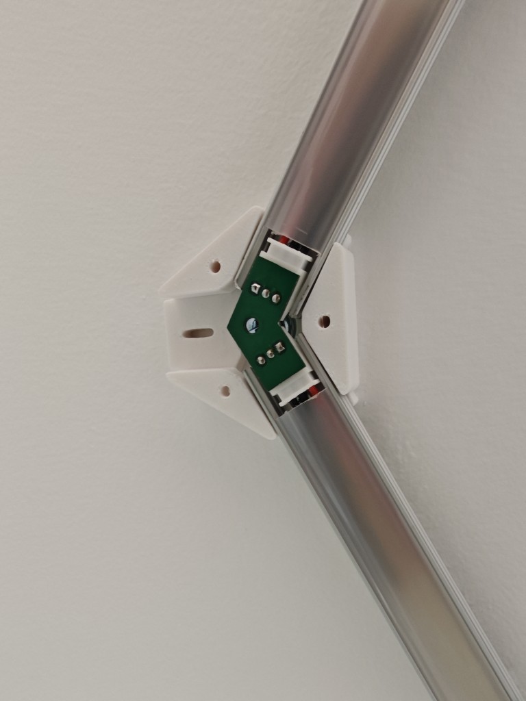
I prepared 3 different cover types: for normal 3-way junctions, for 2-way junctions (outside corners) and for junctions with power connections.
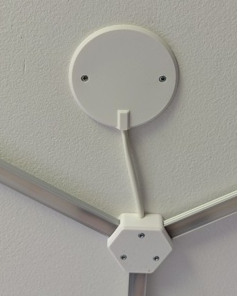
The cables were just tucked in some white heatshrink tube so they don't stand out as much.
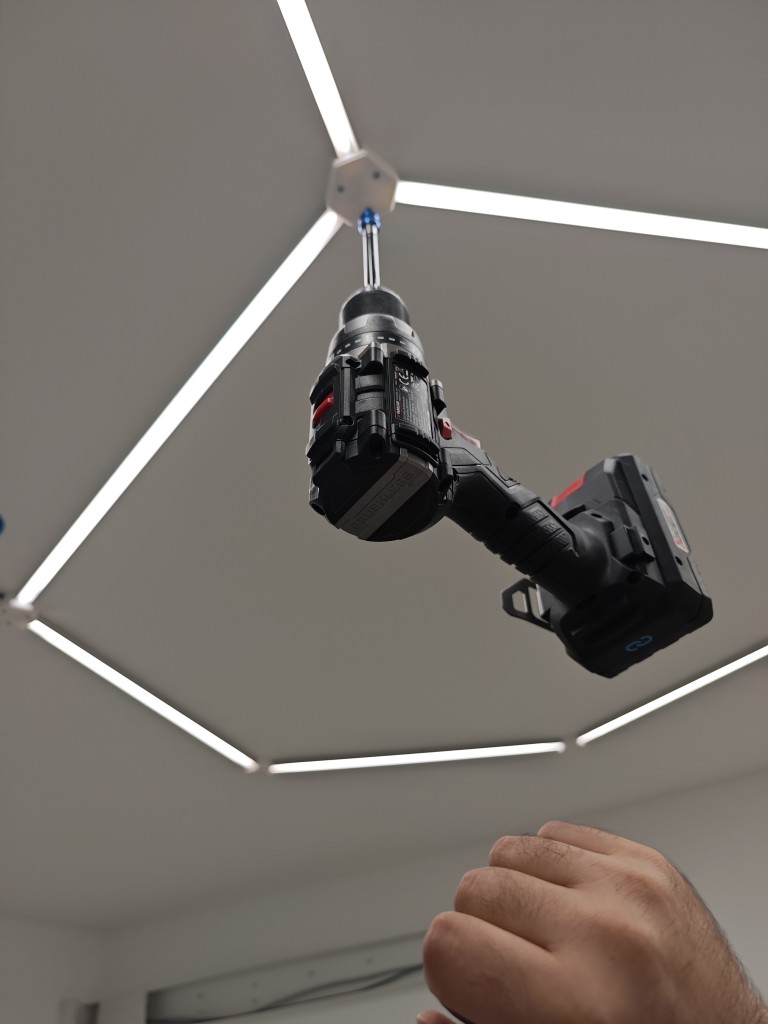
If you use the correct bit for your drill, you can actually hang it from the ceiling 😂
Nothing special, just connect positive wire to positive output and negative CW/WW wires to respective outputs and that's it :)
Included in folder. It's just the example config really, nothing special.
I oriented all PCB the same way - positive rail on "top". This made it much easier to manipulate. Yes, you can keep tossing and turning them around but it did save me some time in the long run.
I also made sure to have all segments that only had cables run from one side, to not use crossed wires. Try to avoid crossed wires as much as possible, they do show through diffuser. I could probably use hot glue or something to fix them but.. Nah :)
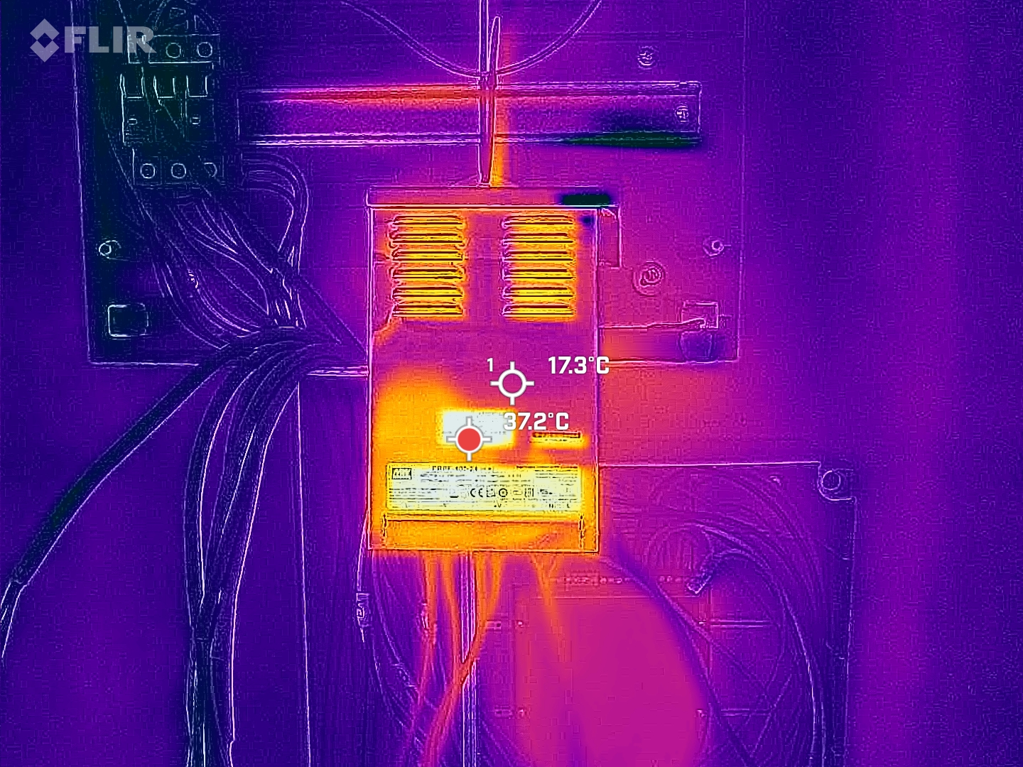
My thermal camera showed no abnormalities when the strips were running at 100% after a few hours of "testing".
LED controller
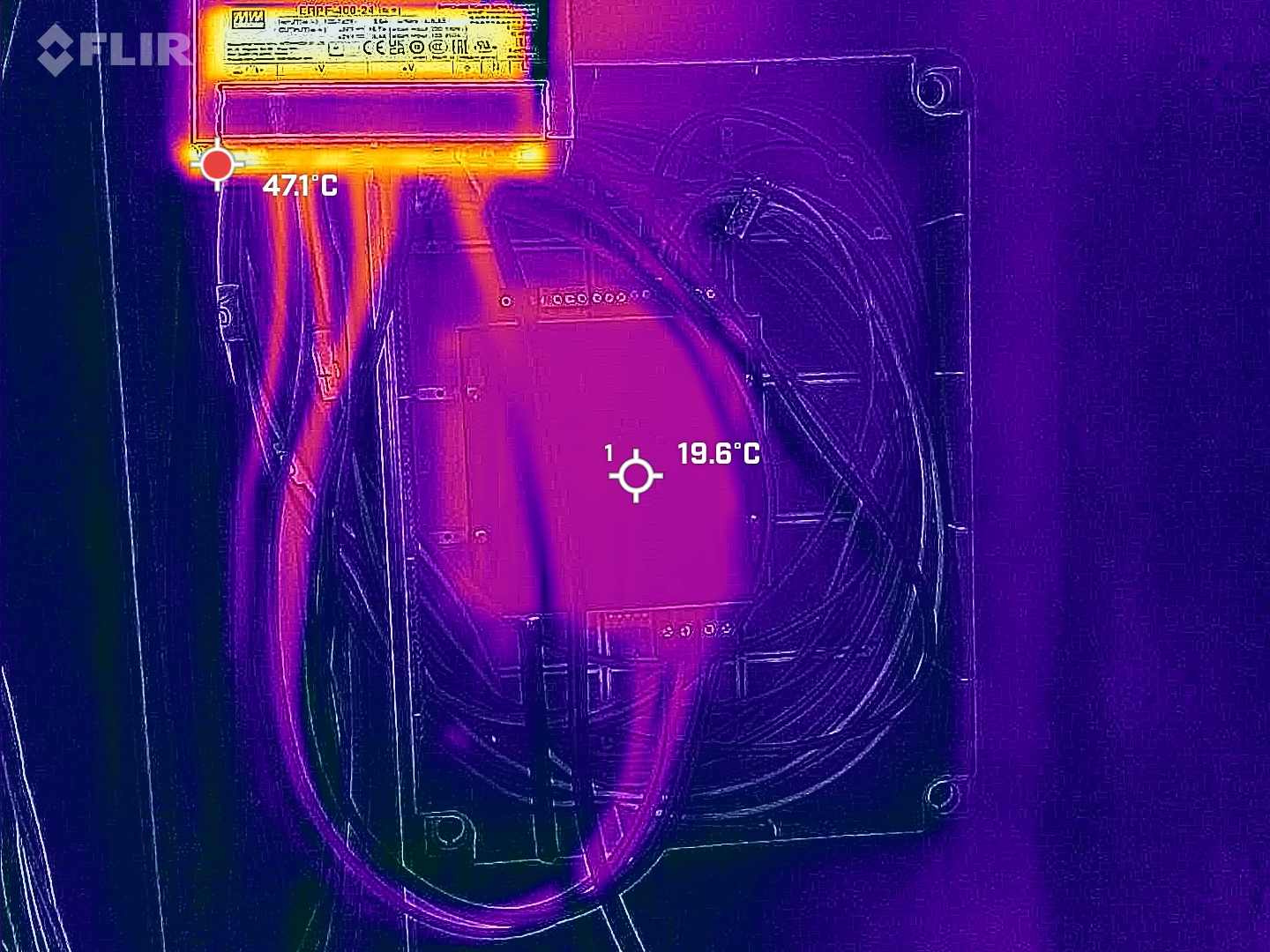
Power supply after 1 hour
Power cables before/after closing them up
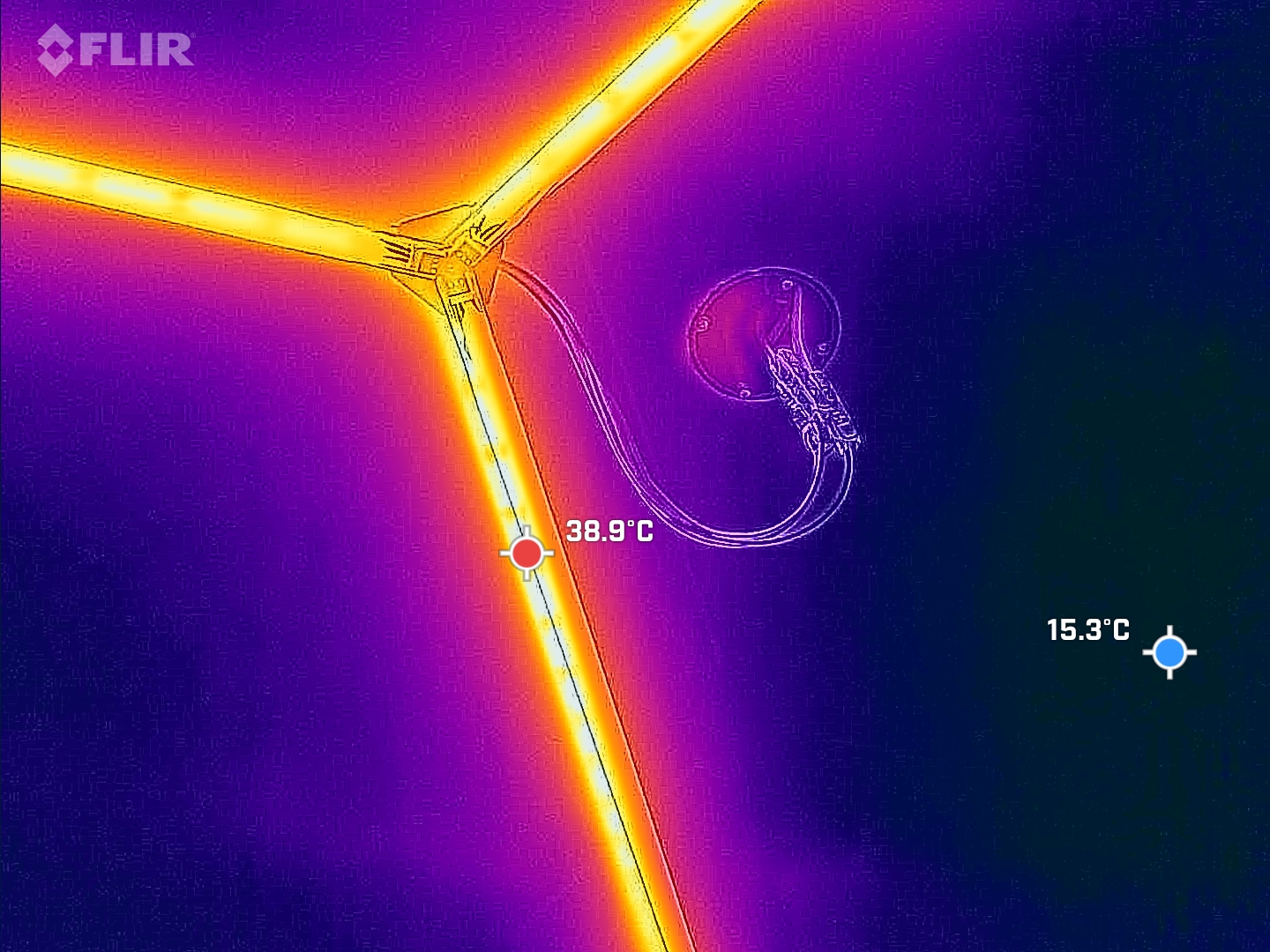
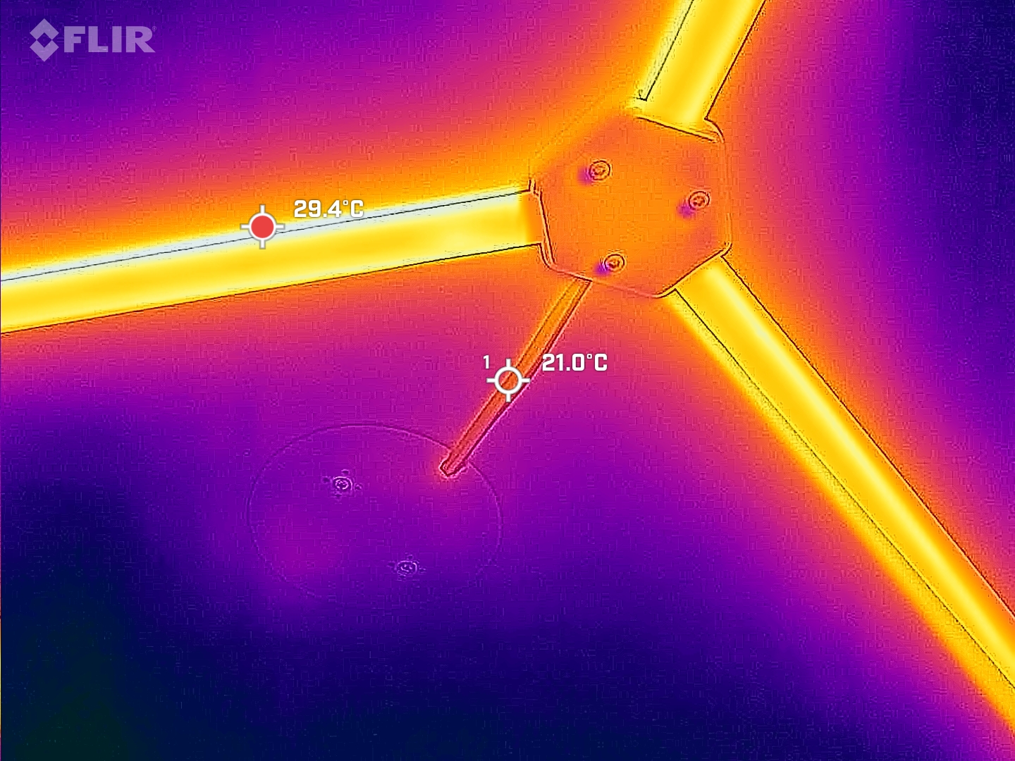
LED strips
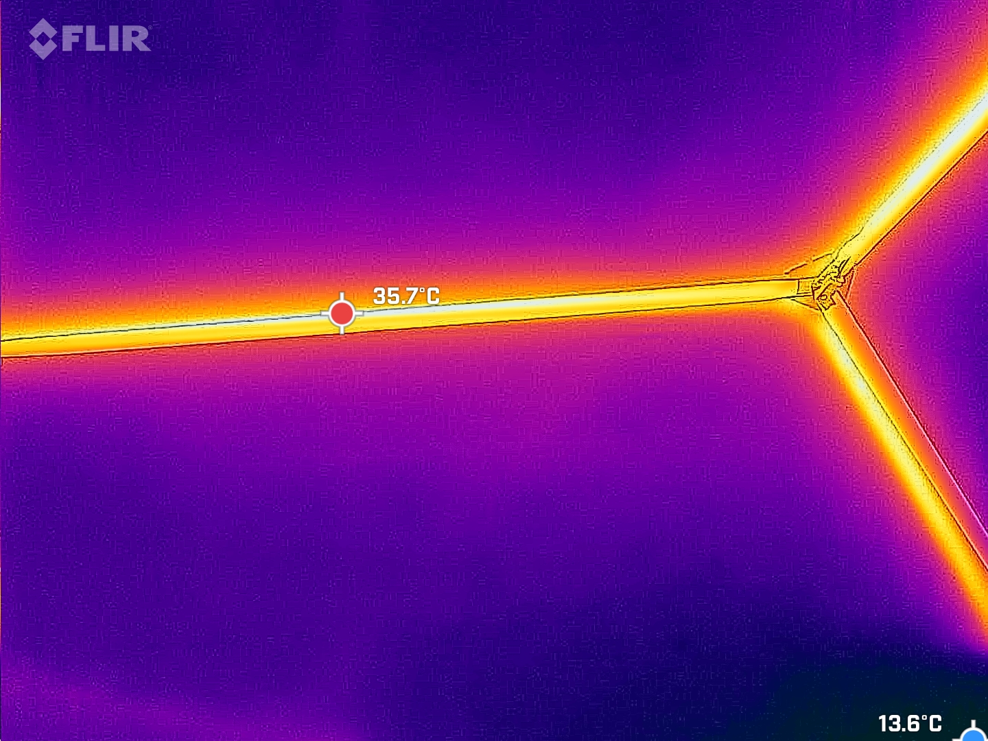
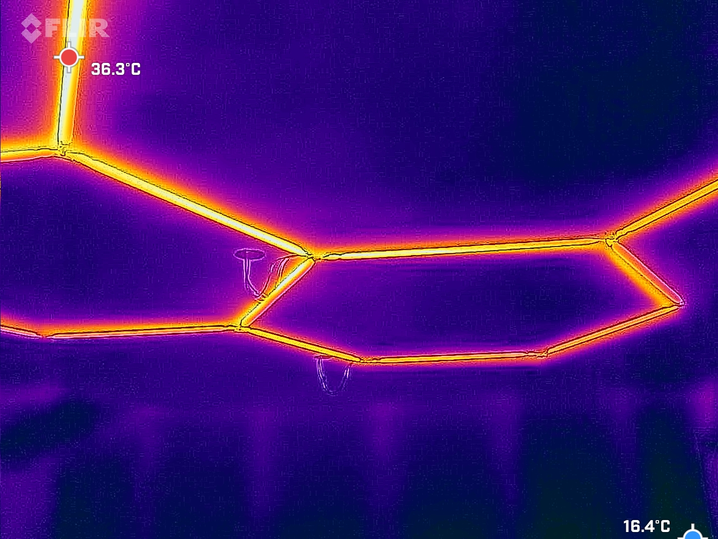
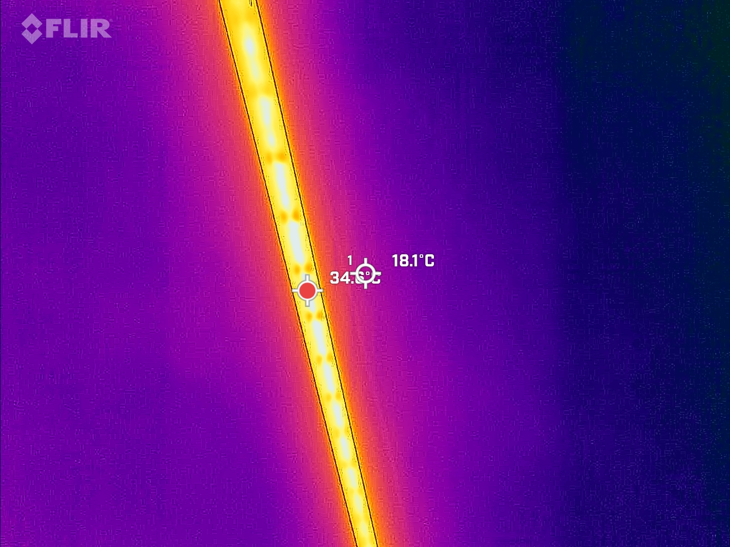
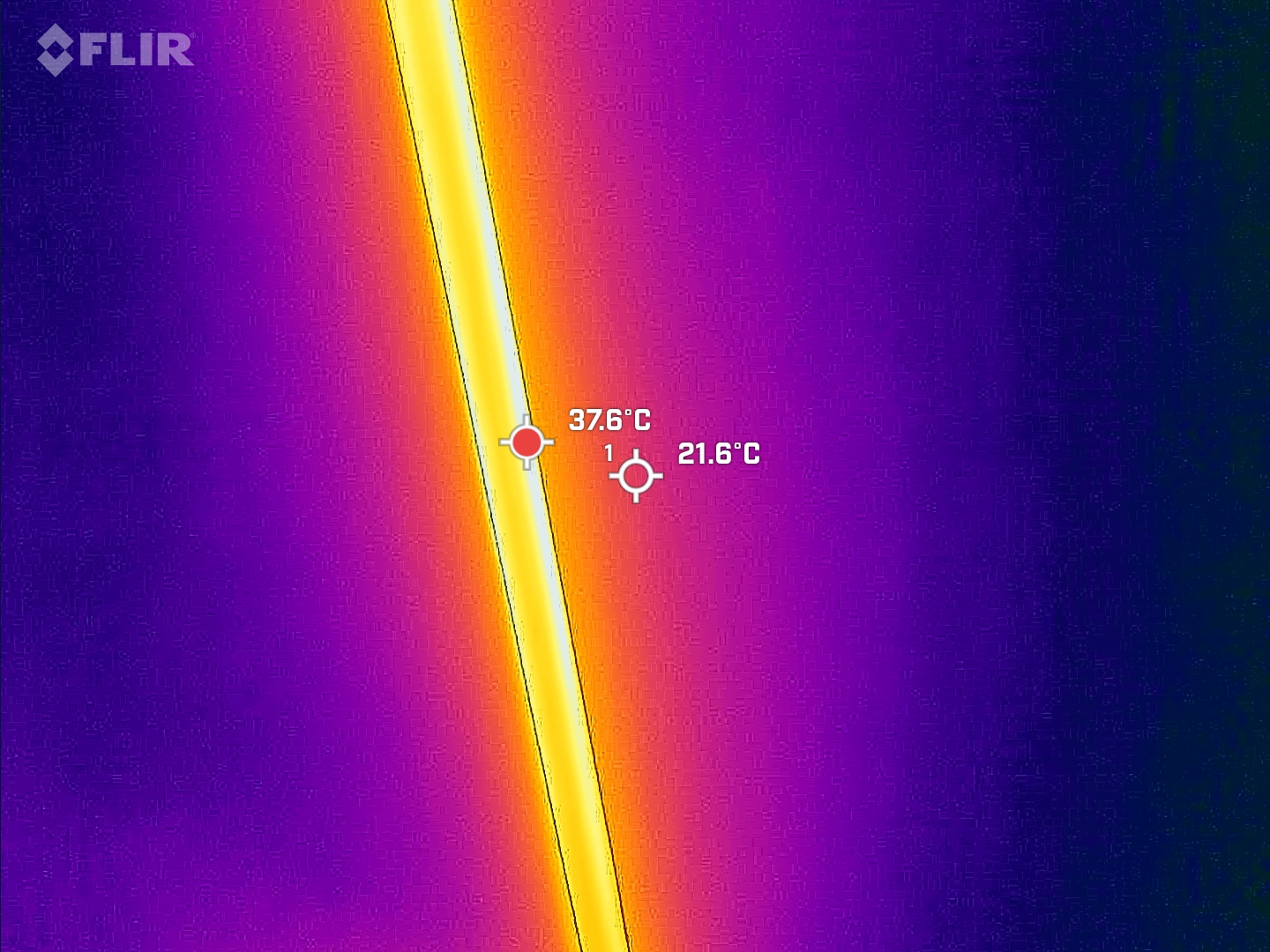
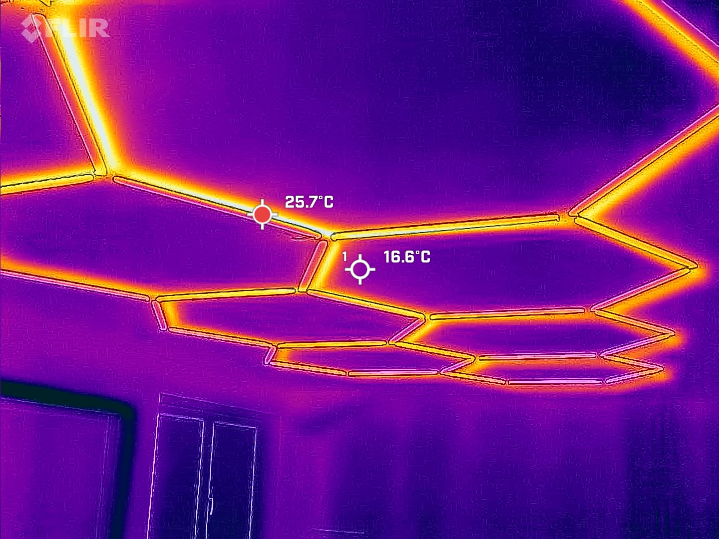
Make sure to not look at things cross-eyed as I apparently have. I triple-checked the length and still managed to cut the strips too short. At least I found out after cutting 6 of them, not all of them. Whew!
I did choose the following options when ordering. The ones you should really pay attention to are "PCB Thickness: 1 mm" & I also chose "Remove mark / order number" simply because there is not much space on the boards.
Base Material: FR-4
Layers: 4
PCB Thickness: 1mm - IMPORTANT!
Specify Stackup: no No requirement
PCB Color: Green
Silkscreen: White
Material Type: FR-4 TG155
Via Covering: Plugged
Surface Finish: HASL(with lead)
Deburring/Edge rounding: Yes
Outer Copper Weight: 1 oz
Inner Copper Weight: 0.5 oz
Mark on PCB: Remove Mark
Confirm Production file: NoI totally overengineered this but.. Oh man it looks nice 😅 Not to mention how much it eliminates shadows! Crazy. Would I do it again? Now that it's done, maybe. If you asked me 2 days before coming to this stage: not a chance!
Interesting info: at output of LED controller, I get 24,04 V and at end of strip that is farthest away, my voltmeter read 23,51 V. That is 0,53 V voltage drop and I think that's pretty good. Maybe I did go a bit overboard with using such thick wire for long runs but.. It is what it is. I'm not changing it now.
Anyway, feel free to download the files and make your own hexagon ceiling lights. Let me know if I forgot to add any details or if you have any questions. This is one of the first projects that I started with when moving to a new apartment.
The lights are set up in my "mancave": I call it "Brlog" - that translates to "den" or "lair" 😅
Hope you enjoyed reading this, it sure was an interesting project for me. Not to mention, this was the first time I had custom 4-layer PCBs made for me 😂
This project is licensed under CC BY-NC 4.0.
You are free to use and remix it for non-commercial purposes, with attribution.
⚠️ Provided as-is. No liability accepted.
| Qty | Value | Footprint | References |
|---|---|---|---|
| 2 | Conn_01x03 | Connector_JST:JST_XH_S3B-XH-A-1_1x03_P2.50mm_Horizontal | J1, J2 |
It measures 19.6 × 25.1 mm and has 4 copper layers, 4.69 mm thick.
2 parts. The full list of its parts is on this page, with links to each part's symbol and footprint where PCBKit's library has them.
From the nejc-cc/hexaled repository on GitHub, at the commit this page was made from: the board is Gerber and KiCad files/HexLED/HexLED.kicad_pcb and its schematic Gerber and KiCad files/HexLED-dvojni/HexLED-dvojni.kicad_sch. PCBKit opens the board in the browser, with nothing to install.
Its repository states no licence, so its author keeps all rights: ask nejc-cc before reusing the design.
drandyhaas/KiCadRoutingTools
A set of Python/Rust tools to aid routing in KiCad


dbalsom/arduinoX86
An interface between an Arduino Due or Arduino GIGA and 8088, 8086, V20, V30, 186 or 286 CPUs

agranlund/raven
Homemade MC68060 + DSP56303 Atari-compatible computer. Hardware, firmware, and software stack


imendizabal/Near-Field-Probes
Open Source kit of Near Field Probes for Electromagnetic Compatibility (EMC) troubleshooting