
6 layers243.8 × 243.8 mm
Raven
agranlund/raven
Homemade MC68060 + DSP56303 Atari-compatible computer. Hardware, firmware, and software stack
331 parts87

 necroware/voltage-blaster80
-5V voltage provider
Voltage blaster is an open-source printed circuit board by necroware, from the necroware/voltage-blaster repository on GitHub, published under the CC0-1.0 licence. It is a 2-layer board of 95.3 × 24.1 mm with 6 parts on 4 nets, routed with 24 tracks and 30 vias.
It is built around the LM7905T. Its parts include 2 capacitors, 1 resistor, 1 IC, 1 diode and 1 connector.
Voltage Blaster is a very simple circuit, which provides -5V through ISA slot for systems with power supply which don't provide such voltage. It was created in cooperation of PhilsComputerLab with Necroware.
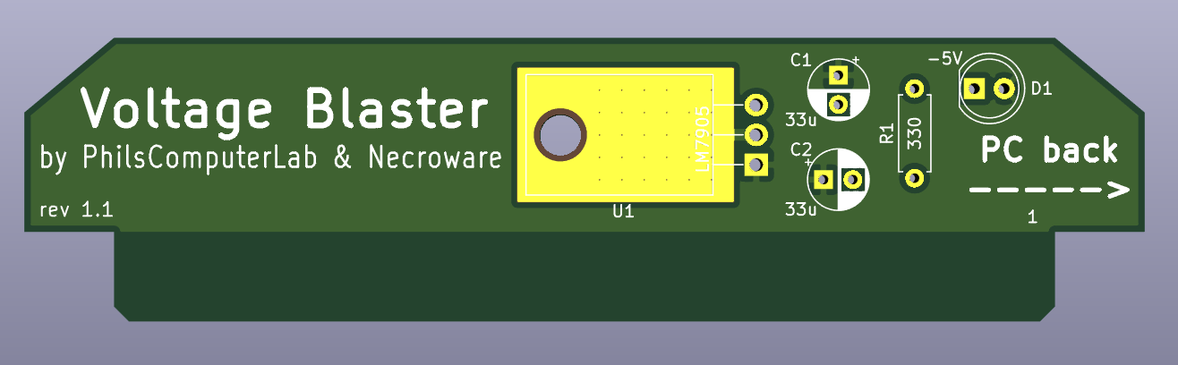
Back in the days of XT and AT compatible computers the standard power supply had to provide 5V, 12V, -12V and -5V. A lot of hardware, especially sound cards, needed -5V to work properly. This voltage was provided for the ISA expansion cards on the pin B5. As time passed, AT systems and compatible power supplies were replaced by ATX. In the beginning they also provided -5V, but then less and less expansion cards needed such voltage and as soon as ISA was considered obsolete, ATX standard eventually dropped -5V rail requirement. Today it is not possible to buy a new AT power supply, but ATX power supplies can be used through an adapter. However, since almost none of the modern ATX power supplies will provide -5V, you could run into problems, when trying to use an old ISA expansion card, which needs this voltage. Famous examples are Creative Sound Blaster 2.0, Pro Audio Spectrum sound cards and many others. This is where the Voltage Blaster comes into play.
All voltage pins in the ISA slots are directly connected to each other and to the PSU. When using a PSU without -5V support, the ISA slot pin B5 is just floating. The idea behind the Voltage Blaster is very simple. What if one of the ISA expansion cards will provide -5V and feed it through the ISA slot in reverse. Well since the ISA slot pin B7 provides -12V, it's just a matter of using a linear voltage regulator LM7905 and connect its output to the pin B5 of the ISA slot.
| Reference | # | LCSC | Description |
|---|---|---|---|
| U1 | 1 | C427634 | linear voltage regulator LM7905 |
| C1,C2 | 2 | C3314 | electrolytic capacitor 33µF |
| D1 | 1 | C99697 | light emitting diode (optional) |
| R1 | 1 | C58608 | resistor 330 Ohm (optional) |
Parts D1 and R1 are optional and are only required if you want that the diode is lighting, when -5V are generated.
| Qty | Value | Footprint | References |
|---|---|---|---|
| 2 | 33u | Capacitor_THT:CP_Radial_D5.0mm_P2.50mm | C1, C2 |
| 1 | -5V | LED_THT:LED_D5.0mm | D1 |
| 1 | 330 | Resistor_THT:R_Axial_DIN0207_L6.3mm_D2.5mm_P7.62mm_Horizontal | R1 |
| 1 | Bus_ISA_8bit | MyLibrary:ISA_8BIT_EDGE | J1 |
| 1 | LM7905 | Package_TO_SOT_THT:TO-220-3_Horizontal_TabDown | U1 |
It measures 95.3 × 24.1 mm and has 2 copper layers, 1.6 mm thick.
6 parts, built around the LM7905T. The full list of its parts is on this page, with links to each part's symbol and footprint where PCBKit's library has them.
From the necroware/voltage-blaster repository on GitHub, at the commit this page was made from: the board is kicad/voltage-blaster.kicad_pcb. PCBKit opens the board in the browser, with nothing to install.
Its repository publishes it under the CC0-1.0 licence: you may reuse it on that licence's terms (keep the author's notice, and for a copyleft licence share your changes alike).
agranlund/raven
Homemade MC68060 + DSP56303 Atari-compatible computer. Hardware, firmware, and software stack

FredericSegard/Fr80
Z80 Homebrew computer, code-named Fre80, pronounced Freddy.

JQIamo/20A-bipolar-current-source
20A bipolar current source with water cooled sensing resistor

skiselev/intel-wildcard-88-motherboard
An IBM PC/XT compatible motherboard utilizing the Intel Wildcard 88 module

muhin19/ATE-PCB-DESIGN
PCB design for an Automatic Test Equipment (ATE) system, including circuit design, component placement, routing, and PCB layout for electronic testing applications.

Toysoft/mb386sx-rc2016
The origin of this project is the M396F motherboard replica by Marco Both. Marco replicated the PCB layout of a certain revision of M396F motherboard. He didn't provide the schematic.

DuPAL-PAL-DUmper/DuPAL_Board
This repository contains the KiCad files and the gerber files for the DuPAL boards.
