
2 layers65 × 30 mm
Rgb to hdmi
hoglet67/RGBtoHDMI
Bare-metal Raspberry Pi project that provides pixel-perfect sampling of Retro Computer RGB/YUV video and conversion to HDMI
36 parts1kGPL-3.0

 necroware/s7-vrm68
Socket 7 Voltage Regulator Module
S7-vrm is an open-source printed circuit board by necroware, from the necroware/s7-vrm repository on GitHub, published under the CC-BY-SA-4.0 licence. It is a 2-layer board of 61.7 × 53 mm with 36 parts on 22 nets, routed with 51 tracks and 39 vias.
It is built around the ISL6545CBZ. Its parts include 15 capacitors, 9 resistors, 4 transistors, 2 connectors and 1 IC. It belongs with the power boards of this library.
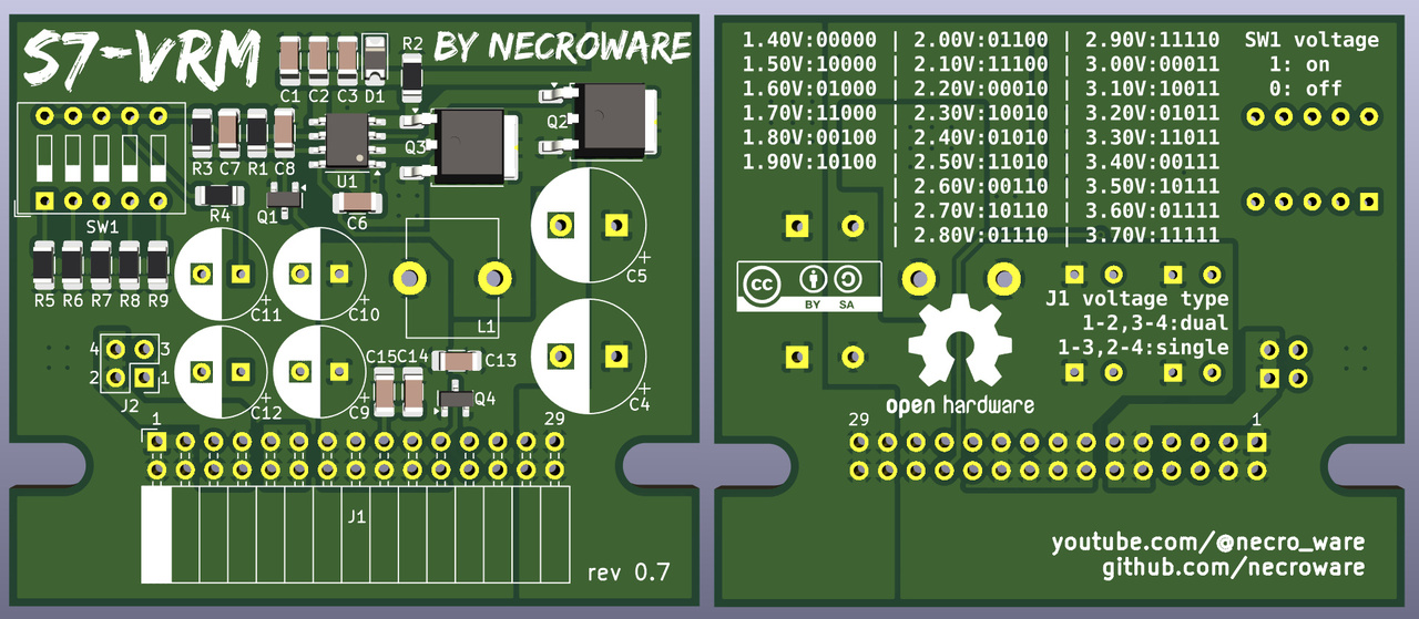
This project is a Voltage Regulator Module for the Socket 7 mainboards as defined by Intel in it's Pentium® Processor Flexible Motherboard Design Guidelines. You can upgrade VRM capable Socket 7 mainboards with this module to be able to use dual-voltage CPUs like Intel Pentium MMX, AMD K6, AMD K6-2 etc.
Disclaimer: this VRM can damage your mainboard, CPU or both. Please use at your own risk.
WARNING: inserting the module the wrong way around would put +12V on all critical lanes. It would destroy the mainboard, the CPU, the memory and all expansion cards. This can't happen on mainboards with VRM socket, because there it is not possible to insert it in reverse. On free standing VRM pin header, it is probably a good idea to cut +12V pin 5 and the unused pin 22 to use them as a key.
Youtube Videos:
There are two kind of socket 7 CPUs, single-voltage and dual-voltage CPUs. Dual-voltage CPUs are designed to use different voltages for the internal core and for the I/O. The I/O voltage is specified at 3.3-3.5V, but the core voltage can be much lower. For the very power efficient AMD K6-III+EE the core voltage is just 1.6V.
From revision 0.6 and higher the S7-VRM supports both types of CPUs, where for the single-voltage CPUs the voltage is completely generated on the module and for dual-voltage CPUs the I/O voltage is generated by a linear voltage regulator on the mainboard, where core voltage is generated on the VRM module.
To make this work you have to set the jumper J1 accordingly. Please read which kind of CPU you have before using this module.
| Voltage Type | J1 Pos. | CPU examples |
|---|---|---|
| Single | 1-3, 2-4 | Intel Pentium, AMD K5, Winchip C6, Cyrix M1 |
| Dual | 1-2, 3-4 | Intel Pentium MMX, AMD K6, Cyrix M1L/MII |
WARNING: Single voltage CPUs are designed to run at 3.3-3.5V everything below that value could potentially make your system unstable. Everything above that can damage your mainboard or CPU or both. Dual-voltage CPUs usually need core voltages far below 3.0V, AMD K6-2 for example expects only 2.2V core voltage and everything above that can potentially damage the CPU. Always pay attention to the CPU type you use and apply voltages out of spec only if you really know what you are doing.
WARNING: different revisions can have different voltage settings, please always pay attention and look into the proper documentation for the revision you have.
Various voltages can be set using the SW1 switch on the module (0=off, 1=on):
| Voltage | Switches | CPU Examples |
|---|---|---|
| 1.4V | 00000 | Probably too low for any S7 CPU |
| 1.5V | 10000 | |
| 1.6V | 01000 | AMD K6-2E+ / K6-3E+ / Mobile K6-2 |
| 1.7V | 11000 | |
| 1.8V | 00100 | |
| 1.9V | 10100 | |
| 2.0V | 01100 | Cyrix MII (0,18µm version) |
| 2.1V | 11100 | |
| 2.2V | 00010 | AMD Mobile K6 / K6-2(+) / K6-3(+) |
| 2.3V | 10010 | |
| 2.4V | 01010 | AMD K6-2 |
| 2.5V | 11010 | |
| 2.6V | 00110 | |
| 2.7V | 10110 | |
| 2.8V | 01110 | Intel Pentium MMX, IBM 6x86L, Rise MP6 |
| 2.9V | 11110 | AMD K6, IBM 6x86MX |
| 3.0V | 00011 | |
| 3.1V | 10011 | |
| 3.2V | 01011 | AMD K6@233 |
| 3.3V | 11011 | Pentium 66-200 (Single Voltage) |
| 3.4V | 00111 | |
| 3.5V | 10111 | AMD K5, Winchip C6 |
| 3.6V | 01111 | |
| 3.7V | 11111 | Danger: probably to high for any S7 CPU |
The transistor Q1 with integrated pull-up resistor is optional. It is used for enable/disable signal and is unused on most mainbards.
The PCB is made for a through hole inductor, but if you have only SMD it is also possible to solder that instead. Keep in mind that the inductor has to stand the required current. Also slightly different inductors are allowed, everything between 2µH and 4,7µH should work as well. With the higher inductance you get less current ripple, also voltage ripple can look better, but the maximum possible current will decrease. Playing with different inductors will also influence the compensation network.
Capacitors C7 and C8 are used in so called compensation network and are responsible for DC-DC converter activation and stability. Those parts are very delicate and dependent on the ESR and values of the output capacitors C9-C12, and the inductor L1. If your regulator shows stability issues or not starting at all, try to remove the capacitor C8. If you change any other parts C7, C8 and R1 have to be adapted accordingly.
| Part | Count | LCSC# | Comment |
|---|---|---|---|
| C1, C15 | 2 | C13585 | 10u capacitor SMD 1206 |
| C2, C14 | 2 | C51205 | 4.7u capacitor SMD 1206 |
| C3, C6, C13 | 3 | C696845 | 0.1u capacitor SMD 1206 |
| C4, C5 | 2 | C407963 | 2200u capacitor TH Radial D10.0mm, P5.00mm |
| C7 | 1 | C107186 | 242n capacitor SMD 1206 |
| C8 | 1 | C577176 | 39p capacitor SMD 1206 |
| C9-C12 | 4 | C407858 | 1000u capacitor TH Radial D8.0mm, P3.5mm |
| D1 | 1 | C109000 | Switching diode |
| J1 | 1 | C2897435 | Connector angled 02x15 pins 2.54mm |
| J2 | 1 | N/A | 2x2 jumper |
| L1 | 1 | N/A | 3.3µH inductor |
| Q1 | 1 | C13871 | NPN-BEC biased transistor |
| Q2, Q3 | 2 | C496603 | N-MOSFET GDS at least 15A |
| Q4 | 1 | C454937 | PNP-BEC biased transistor |
| R1, R2, R6 | 3 | C136874 | 15K resistor SMD 1206 |
| R3, R8, R9 | 3 | C706412 | 3,75K resistor SMD 1206 |
| R4 | 1 | C870818 | 5K resistor SMD 1206 |
| R5 | 1 | C137314 | 30K resistor SMD 1206 |
| R7 | 1 | C137115 | 7,5K resistor SMD 1206 |
| SW1 | 1 | C5299506 | DIP-10 Switch THT 5 buttons 2.54mm |
| U1 | 1 | C382017 | ISL6545 DC-DC Controller |
The inductor doesn't need to be very exact, anything between 2.5µH and 4.7µH should work, but the sweet point is at around 3.3µH. The inductor can be self made by using a T50 ferrite toroid. For example T50-26 with permeability 75µ wrapped in 10 loops of 1.3 mm coper.
This module should run with all mainboards, which provide the VRM module header as specified in Intel Pentium Mainboard Design Guidelines. Most of such boards were based on Intel Triton (i430FX) and VIA Apolo Master (MV series) chipsets, but there were also quite a lot of later boards with newer chipsets (f.e. i430VX), which supported such an external VRM as well.
Most of the mainboards which were equipped with a VRM option, were produced before Intel Pentium MMX, AMD K6 and other dual-voltage CPUs were officially available. However those CPUs have changed the multiplier selection behavior of CPU pins BF0/1. Not only a new pin was introduced for higher multipliers, but also pin BF0 was not pulled up internally anymore as it has been done on single-voltage CPUs before. This ended up in wrong multiplier detection on newer CPUs like Pentium MMX 200, which would be suddenly detected as 166MHz one. This can be fixed by adding a 10k pull-up resistor to the CPU between pin BF0 I/O VCC.
Faster Super Socket 7 CPUs, like AMD K6-2 and newer added another multiplier selection pin BF2, which is not supported on those old mainboards at all. It can be added using another mod, but is actually not necessary. If the CPU multiplier is set to 2x, those newer CPUs would interpret it as 6x and for 66MHz FSB go directly to 400MHz. However to be able to detect the CPU properly you would need to mod the BIOS. This is however optional, the system should work also with outdated BIOS. In such a case the CPU just would not be reported properly.
For the list of tests mainboards see: https://github.com/necroware/s7-vrm/wiki
This work is licensed under the Creative Commons Attribution-ShareAlike 4.0 International License.
| Qty | Value | Footprint | References |
|---|---|---|---|
| 4 | 1000u | Capacitor_THT:CP_Radial_D8.0mm_P3.50mm | C9, C10, C11, C12 |
| 3 | 100n | Capacitor_SMD:C_1206_3216Metric_Pad1.33x1.80mm_HandSolder | C3, C6, C13 |
| 3 | 15K | Resistor_SMD:R_1206_3216Metric_Pad1.30x1.75mm_HandSolder | R1, R2, R6 |
| 3 | 3,75K | Resistor_SMD:R_1206_3216Metric_Pad1.30x1.75mm_HandSolder | R3, R8, R9 |
| 2 | 10u | Capacitor_SMD:C_1206_3216Metric_Pad1.33x1.80mm_HandSolder | C1, C15 |
| 2 | 2200u | Capacitor_THT:CP_Radial_D10.0mm_P5.00mm | C4, C5 |
| 2 | 4.7u | Capacitor_SMD:C_1206_3216Metric_Pad1.33x1.80mm_HandSolder | C2, C14 |
| 2 | Q_NMOS_GDS | Package_TO_SOT_SMD:TO-252-2 | Q2, Q3 |
| 1 | 242n | Capacitor_SMD:C_1206_3216Metric_Pad1.33x1.80mm_HandSolder | C7 |
| 1 | 3,3u | Inductor_THT:L_Toroid_Vertical_L16.0mm_W8.0mm_P7.62mm | L1 |
| 1 | 30K | Resistor_SMD:R_1206_3216Metric_Pad1.30x1.75mm_HandSolder | R5 |
| 1 | 39p | Capacitor_SMD:C_1206_3216Metric_Pad1.33x1.80mm_HandSolder | C8 |
| 1 | 5K | Resistor_SMD:R_1206_3216Metric_Pad1.30x1.75mm_HandSolder | R4 |
| 1 | 7,5K | Resistor_SMD:R_1206_3216Metric_Pad1.30x1.75mm_HandSolder | R7 |
| 1 | Conn_02x02_Odd_Even | Connector_PinHeader_2.54mm:PinHeader_2x02_P2.54mm_Vertical | J2 |
| 1 | Conn_02x15_Row_Letter_First | Connector_PinSocket_2.54mm:PinSocket_2x15_P2.54mm_Horizontal | J1 |
| 1 | D | Diode_SMD:D_1206_3216Metric_Pad1.42x1.75mm_HandSolder | D1 |
| 1 | ISL6545 | Package_SO:SOIC-8_3.9x4.9mm_P1.27mm | U1 |
| 1 | LOGO | s7-vrm:cc-by-sa-logo | G*** |
| 1 | Q_NPN_BEC_BRT | Package_TO_SOT_SMD:SOT-23 | Q1 |
| 1 | Q_PNP_BEC_BRT | Package_TO_SOT_SMD:SOT-23 | Q4 |
| 1 | SW_DIP_x05 | Button_Switch_THT:SW_DIP_SPSTx05_Slide_9.78x14.88mm_W7.62mm_P2.54mm | SW1 |
The 35 most common of 36 parts.
hoglet67/RGBtoHDMI
Bare-metal Raspberry Pi project that provides pixel-perfect sampling of Retro Computer RGB/YUV video and conversion to HDMI

hackclub/OnBoard
💡 Join 1,000 teenagers and make your first PCB with a $100 grant!


tardate/LittleArduinoProjects
a collection of "Little Electronic & Arduino Projects", most involving electronics or an Arduino in one way or another!


Neumi/open_echo
Open Source echo sounder / depth sounder / SONAR for bathymetry and research. Arduino based and compatible.


It measures 61.7 × 53 mm and has 2 copper layers, 1.6 mm thick.
36 parts, built around the ISL6545CBZ. The full list of its parts is on this page, with links to each part's symbol and footprint where PCBKit's library has them.
From the necroware/s7-vrm repository on GitHub, at the commit this page was made from: the board is kicad/s7-vrm.kicad_pcb and its schematic kicad/s7-vrm.kicad_sch. PCBKit opens the board in the browser, with nothing to install.
Its repository publishes it under the CC-BY-SA-4.0 licence: you may reuse it on that licence's terms (keep the author's notice, and for a copyleft licence share your changes alike).