
2 layers40 × 55 mm

 necroware/ps2-serial-mouse-adapter89
PS/2 to serial port mouse adapter
Ps2-serial mouse adapter is an open-source printed circuit board by necroware, from the necroware/ps2-serial-mouse-adapter repository on GitHub, published under the GPL-3.0 licence. It is a 2-layer board of 60.5 × 31.5 mm with 13 parts on 44 nets, routed with 81 tracks and 0 vias.
It is built around the MAX232N. Its parts include 5 capacitors, 2 ICs and 1 resistor. It belongs with the interfaces and adapters boards of this library.
Many retro PCs were used with serial port mouse and don't have any PS/2 ports. Unfortunately most of the serial mice are broken or expensive today. Furthermore they were mechanical devices with a heavy steel ball to track the movement. This mechanics got dirty quite fast and was not the best user experience anyway. A better solution are optical PS/2 mice, most of which unfortunately would not work on a serial port. This adapter can be used to connect such a PS/2 mouse to a serial port of a retro PC.The Adapter is made from through-hole parts only, so it is very easy to solder and due to Arduino based solution, it is also a very nice device for tinkering, experimenting and learning about mouse protocols.
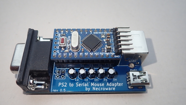
The serial port on the computer communicates with the mouse using basically two pins - RTS and RX. RTS is used for notification and RX for the actual data transfer, which contains mouse position, buttons state etcetera. A standard PS/2 mouse on the other hand uses completely incompatible protocol and transfers the data between the mouse and the computer using the Data and Clock pins. If we want to connect a PS/2 mouse, to a serial port, we need some instance in between, to translate between the two different protocols. In this adapter the translation is done using an Arduino Mini. However, there is another problem. PS/2 mouse protocol uses so called TTL logic, which simply means, that the voltage of 0V means a logical zero and 5V means a logical one. TTL logic is what Arduino uses as well, but a serial port, or also called RS232, uses another voltage levels. Any voltage below -3V is a logical one and a voltage above +3V is a logical zero. So, it is not possible to connect Arduino output directly to the serial port. It simply will not work and needs another translator, which converts TTL voltage level to RS232 levels. In this adapter such conversion is made by a well known MAX232 IC. The software is written in C/C++, it is a simple Arduino project, which can be used in Arduino Studio as usual.
This project contains everything you need to build your own adapter. You can use the gerber files to order a PCB. The list of materials is below. After soldering the adapter, connect the Arduino Mini using an USB to TTL adapter to your PC and flash the firmware using the Arduino IDE. If you don't know how to do that, please refer to the documentation of Arduino.
ATTENTION! The USB port (PWR1) on the adapter is only for powering the circuits, it is not a data port!
Connecting the adapter to the PC is very simple. Plug your PS/2 Mouse into the adapter, connect a mini USB cable to power the adapter. Plug the adapter into a serial port of your PC. Turn on the PC and use a serial mouse driver of your choice. The adapter was tested with Microsoft, Logitech and Cute mouse drivers. Cute Mouse Driver is part of FreeDos project and is free and open source.
There are two jumpers, which can be used to set different modes. Currently you can choose between 2- and 3-button mouse modes and select so called remote and streaming mode. Remote mode sends mouse data all the time and has a better response times in current implementation. Streaming mode sends only data, when mouse position or button state changes. Unfortunately, this mode is currently not in a good shape. It has a higher delay and can result in some timing issues. However, it is interesting to have it for experimental purpose. Default values are when the jumpers are unset.
| JP1 | Setting | Description |
|---|---|---|
| 1-2 | unset | 3-button Logitech mouse |
| 1-2 | set | 2-button Microsoft mouse |
| 3-4 | unset | remote mode |
| 3-4 | set | streaming mode (experimental) |
| Reference | # | LCSC | Description |
|---|---|---|---|
| U1 | 1 | Arduino Pro Mini 5V (ATMega168 or better) | |
| U2 | 1 | C911187 | MAX232 or compatible DIP16 package |
| RS232 | 1 | C141882 | DB9 female RS232 port |
| MOUSE1 | 1 | C77848 | PS/2 female port |
| PWR1 | 1 | C46398 | Mini-USB port for power supply |
| C1-5 | 5 | C106448 | 1µF electrolytic capacitor |
| R1 | 1 | C57436 | 10kOhm resistor (pull-up) |
| JP1 | 1 | 2x2 jumper header (optional) |
The code is still in development. It works, but it still has some flaws. Timing is really important in this project and sometimes mouse drivers seem not to get a response in time from the adapter. Usually just executing the driver once again will initialize the mouse.
If you test the adapter with a mouse, which is not in this list please consider to submit a report to improve the compatibility of the adapter.
| Qty | Value | Footprint | References |
|---|---|---|---|
| 5 | 1u | Capacitor_THT:CP_Radial_D4.0mm_P1.50mm | C1, C2, C3, C4, C5 |
| 1 | 10K | Resistor_THT:R_Axial_DIN0207_L6.3mm_D2.5mm_P7.62mm_Horizontal | R1 |
| 1 | Arduino_Mini | Package_DIP:DIP-24_W15.24mm_Socket | U1 |
| 1 | Conn_02x02_Odd_Even | Connector_PinSocket_2.54mm:PinSocket_2x02_P2.54mm_Vertical | JP1 |
| 1 | DB9_Female | Connector_Dsub:DSUB-9_Female_Horizontal_P2.77x2.84mm_EdgePinOffset7.70mm_Housed_MountingHolesOffset9.12mm | RS232 |
| 1 | MAX232 | Package_DIP:DIP-16_W7.62mm_Socket | U2 |
| 1 | Mini-DIN-6 | ps2-serial-mouse-adapter:Mini_DIN_6_LCSC_C77848 | MOUSE1 |
| 1 | USB_B_Mini | ps2-serial-mouse-adapter:USB_Mini-B-Jing_Extension_LSCS_C46398 | PWR1 |
The 12 most common of 13 parts.

peterheinrich/InternetOverSpaghetti
Transmitting IP packages over a pair of spaghetti thus demonstrating how media independent IP really is.

LimeProgramming/USB-serial-mouse-adapter
Convert USB mouse to Serial mouse using Pi Pico

RetroFuturisticEngineer/RetroARDUInput
Use USB Keyboards, Mice and Joysticks on PC/XT, PC/AT, Tandy 1000, Atari, Amiga, C64 and Apple

jbevren/6809v2
Code and design repository for the 6809v2 SBC: To be released at VCFMW 13

cyberboy666/_transcribe_
midi to rs232 bridge - for performance control of old video mixers and switchers

AK-Homberger/NMEA0183-WiFi-Multiplexer
Reads NMEA0183 messages from two serial lines and forwards multiplexed messages to USB-Serial and WLAN as UDP broadcast.

lynchaj/rhyophyre
Single Board Computer featuring Zilog Z180 processor and NEC µPD7220 Graphics Display Controller
It measures 60.5 × 31.5 mm and has 2 copper layers, 1.6 mm thick.
13 parts, built around the MAX232N. The full list of its parts is on this page, with links to each part's symbol and footprint where PCBKit's library has them.
From the necroware/ps2-serial-mouse-adapter repository on GitHub, at the commit this page was made from: the board is kicad/ps2-serial-mouse-adapter.kicad_pcb and its schematic kicad/ps2-serial-mouse-adapter.kicad_sch. PCBKit opens the board in the browser, with nothing to install.
Its repository publishes it under the GPL-3.0 licence: you may reuse it on that licence's terms (keep the author's notice, and for a copyleft licence share your changes alike).