2 layers98 × 27 mm

 necroware/287-booster9
Interposer for 287 FPU with clock mode jumper
287-booster is an open-source printed circuit board by necroware, from the necroware/287-booster repository on GitHub, published under the CC-BY-SA-4.0 licence. It is a 2-layer board of 24.9 × 51.6 mm with 5 parts on 40 nets, routed with 88 tracks and 0 vias.
Its parts include 2 ICs, 1 resistor and 1 connector. It belongs with the lEDs and displays boards of this library.
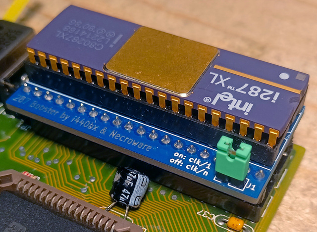
This is an interposer which adds a jumper which can be used to select the clock divider on a 287 floating point unit. It was designed and open sourced in cooperation with the user i440bx from the German dosreloaded.de community.
Intel 287 co-processors have configuration pin 39 for the clock mode signal (CKM) setup. When this pin is pulled up the chip will use the clock directly. If it is pulled to ground the chip will use a clock divider. The pin has internal pull-down resistor, so it can be left unconnected, which will default the setting to divided clock. Which divider will be used depends on the chip:
| Qty | Value | Footprint | References |
|---|---|---|---|
| 1 | 10K | Resistor_THT:R_Axial_DIN0207_L6.3mm_D2.5mm_P7.62mm_Horizontal | R1 |
| 1 | 80287 | Package_DIP:DIP-40_W15.24mm_Socket | U1 |
| 1 | Conn_01x02_Female | Connector_PinHeader_2.54mm:PinHeader_1x02_P2.54mm_Vertical | J1 |
| 1 | Socket | Package_DIP:DIP-40_W15.24mm | U2 |
The 4 most common of 5 parts.

joypad-ai/joypad-os
Universal controller firmware for building adapters, dongles, and custom controllers.

OLIMEX/OLINUXINO
OLINUXINO is Open Source / Open Hardware, low cost from EUR 24 Linux Industrial grade Single Board Computer capable to operate -25+85C

jamro/tiny-engineer
A small desktop robot that brings an AI coding assistant to life, physically acting out when it reads files, thinks, writes code, and finishes work.

hackclub/OnBoard
💡 Join 1,000 teenagers and make your first PCB with a $100 grant!


Luos-io/luos_engine
Open-source and real-time orchestrator for cyber-physical-systems, to easily design, test and deploy embedded applications and digital twins.
It measures 24.9 × 51.6 mm and has 2 copper layers, 1.6 mm thick.
5 parts. The full list of its parts is on this page, with links to each part's symbol and footprint where PCBKit's library has them.
From the necroware/287-booster repository on GitHub, at the commit this page was made from: the board is kicad/287-booster.kicad_pcb and its schematic kicad/287-booster.kicad_sch. PCBKit opens the board in the browser, with nothing to install.
Its repository publishes it under the CC-BY-SA-4.0 licence: you may reuse it on that licence's terms (keep the author's notice, and for a copyleft licence share your changes alike).