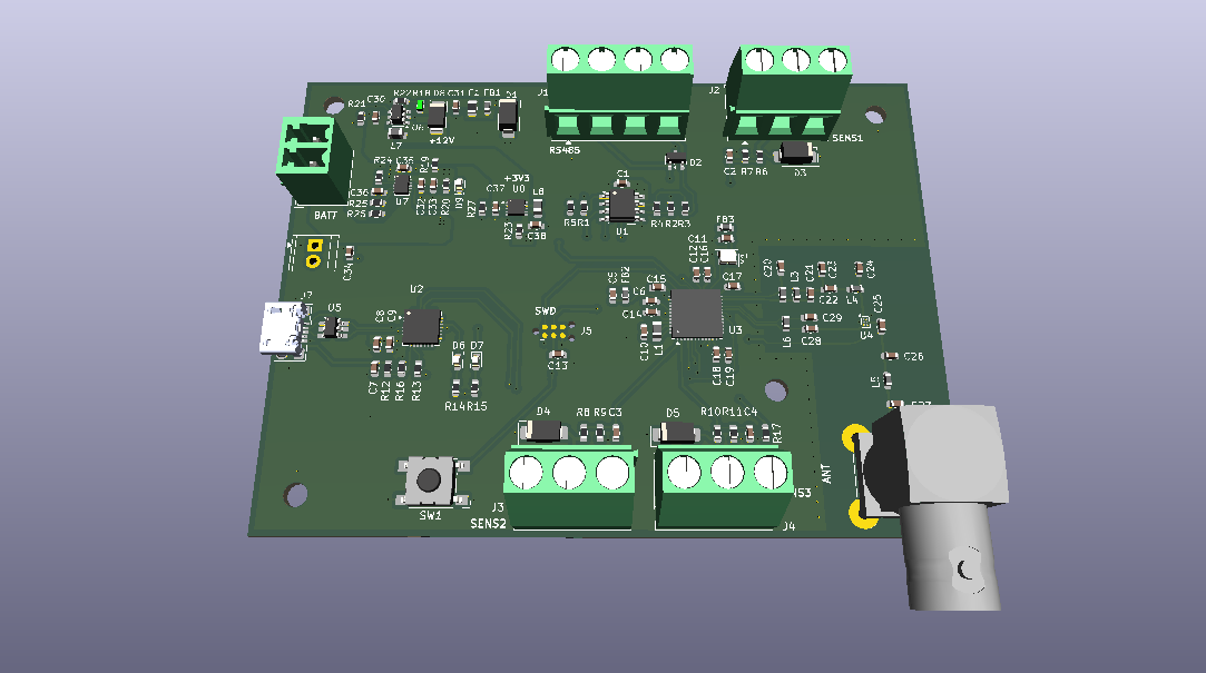
Demo LoRa Node is an open-source printed circuit board by nborkowetz, from the nborkowetz/STM32WL_LoRaSensorNodeDemo repository on GitHub. It is a 4-layer board of 94.5 × 69.7 mm with 109 parts on 105 nets, routed with 549 tracks and 191 vias.
It is built around the BGS 12WN6 E6327, THVD1400D and MT3608, with the SMAJ6.0CA and SMAJ12CA among its other parts. Its parts include 38 capacitors, 27 resistors, 9 diodes, 8 ICs and 8 connectors. It belongs with the radio and wireless and home automation and IoT boards and the STM32 boards of this library.
Low-power LoRaWAN sensor node based on the STM32WL55, originally designed as a prototype platform for distributed water-monitoring applications.
The original goal was not to build a complete water-quality instrument around a fixed set of probes, but to validate the overall sensing and communication architecture first: a battery-powered node, generic sensor interfaces, LoRaWAN connectivity, a local gateway and a self-hosted backend.
Water monitoring may involve very different sensors and analog front-ends depending on the quantity being measured. For this reason, the sensing layer is intentionally kept generic while the project focuses on validating the reusable parts of the system.
Concept
The prototype is intended as a test platform for the complete data path:
text
Sensor / External AFE
        |
   Analog / RS-485
        |
        v
   STM32WL55 Node
        |
      LoRaWAN
        |
        v
   Dragino Gateway
        |
        v
    ChirpStack
        |
       MQTT
        |
        v
   Backend / Web UI
The custom node provides a small set of generic interfaces:
3× protected and filtered analog inputs
RS-485 interface
Switchable 12 V sensor supply
STM32WL55 integrated Sub-GHz radio
USB-UART debug interface
Battery-powered / low-power operation
Sensor-specific amplification, isolation or signal conditioning can be added externally when required.
This allows the LoRaWAN architecture, power-management strategy and backend to be developed independently from the final choice of water-quality sensors.
Firmware
The firmware is being developed around a low-power, event-driven architecture with:
periodic sensor acquisition
timer-triggered ADC sampling with DMA
digital filtering / processing
asynchronous UART / RS-485 communication
sensor power sequencing and warm-up
deep-sleep and periodic wake-up
periodic LoRaWAN uplinks
UART debug console
error handling and watchdog supervision
Typical measurement cycle:
text
Sleep -> Sensor ON -> Warm-up -> Acquire -> Process
      -> Sensor OFF -> LoRaWAN TX (if scheduled) -> Sleep
Firmware development and LoRaWAN validation are currently performed using an STM32WL55 development board. The custom PCB has been designed but has not yet been fabricated.
Synthetic sensor values can be injected during development to validate payload generation and the complete communication path without depending on the final sensing hardware.
LoRaWAN Infrastructure
A second goal of the project is to make the LoRaWAN test environment reproducible and easy to deploy, instead of relying on a manually configured development machine.
The planned local infrastructure consists of:
Dragino LoRaWAN gateway
ChirpStack network server
Mosquitto MQTT broker
containerized deployment with Docker Compose
deployment / provisioning scripts
Python / FastAPI backend for receiving, storing and visualizing measurements
The intended workflow is:
text
docker compose up
        |
        v
ChirpStack + MQTT services
        |
        v
Automated provisioning
        |
        v
Gateway / device registration
        |
        v
End-to-end LoRaWAN test
Configuration files and scripts are kept in the repository so that the test environment can be recreated from a clean machine with minimal manual configuration.
The backend consumes application data exposed by ChirpStack through MQTT; the STM32 node itself only produces the application payload and remains independent from MQTT or the backend implementation.
4-layer RF PCB design of a low-power LoRa sensor node based on STM32WLE5CCU6, featuring 50Ω controlled impedance RF routing, SMA antenna interface, and HDC2022 temperature & humidity sensor. Designed in KiCad.
The separate vNext PCB skill and orchestrator package is available alongside the reference workflow below; existing projects keep their accepted toolchain until an explicit migration.
PIC16F886 based CW auto key controller with USB support
84 parts17MIT
Questions
How big is the Demo LoRa Node PCB?
It measures 94.5 × 69.7 mm and has 4 copper layers, 1.61 mm thick.
What parts does the Demo LoRa Node use?
109 parts, built around the BGS 12WN6 E6327, THVD1400D, MT3608 and SMAJ6.0CA. The full list of its parts is on this page, with links to each part's symbol and footprint where PCBKit's library has them.
Where can I download the Demo LoRa Node KiCad files?
From the nborkowetz/STM32WL_LoRaSensorNodeDemo repository on GitHub, at the commit this page was made from: the board is Hardware/demo LoRa_Node.kicad_pcb and its schematic Hardware/LoRa RF.kicad_sch. PCBKit opens the board in the browser, with nothing to install.
Can I use the Demo LoRa Node design in my own project?
Its repository states no licence, so its author keeps all rights: ask nborkowetz before reusing the design.