4 layers76.2 × 71.1 mm
Fobosshield
GMUCERG/fobos
Flexible Open-source workBench fOr Side-channel analysis (FOBOS)
170 parts18Apache-2.0

 nagutierrez/vdo-breakout
A 4-gauge breakout board for VDO automotive instruments (e.g. Vision Black), with fused 12 V distribution, sender signal routing, and PWM dimming for LED backlighting.
Vdo breakout is an open-source printed circuit board by nagutierrez, from the nagutierrez/vdo-breakout repository on GitHub. It is a 4-layer board of 47 × 48 mm with 37 parts on 21 nets, routed with 80 tracks and 20 vias.
It is built around the ATTINY402-SSN, BAV99 and IRLML2502, with the SMAJ15CA among its other parts. Its parts include 8 resistors, 7 connectors, 5 capacitors, 4 diodes and 2 ICs. It belongs with the interfaces and adapters and microcontroller boards boards and the AVR (ATmega, ATtiny) boards of this library.


A 4-gauge breakout board for VDO automotive instruments (e.g. Vision Black), with fused 12 V distribution, sender signal routing, and PWM dimming for LED backlighting.
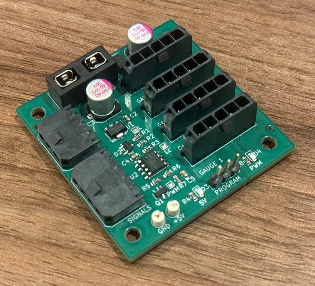
VDO gauges (e.g. Vision Black) terminate in 4–5 individual spade connectors, not a single harness plug: 2 or 3 for the gauge (12v power, ground, and usually a sender/sense) plus 2 for the bulb (Light+, Light−). Wiring these directly in a custom dash in place is tedious.
This board consolidates those spade connections into four gauge ports (Molex Micro-Fit) plus dedicated power and signal headers — one harness per gauge instead of a handful of loose spades.
LED backlighting does not dim with a stock rheostat alone. An ATtiny402 reads the vehicle dimmer input and PWM-switches the shared Light− return via an IRLML2502 MOSFET so LED backlights track the dash lighting level.
flowchart LR
  Rheostat["Vehicle rheostat"] --> ADC["ATtiny402 ADC"]
  ADC --> PWM["PWM output"]
  PWM --> MOSFET["Q1 MOSFET"]
  MOSFET --> LightMinus["Gauge Light−"]
  Ign12V["Ignition 12V"] --> Gauges["4× gauge connectors"]
Gauges --> SenseHeader["Signals header"]hardware/Molex 43650-0515 (one per gauge). PCB silk: L− L+ GND 12V S^N
| Pin | Signal |
|---|---|
| 1 | Sense (sender) |
| 2 | +12V (ignition-switched gauge power) |
| 3 | GND |
| 4 | Light+ |
| 5 | Light− (PWM-switched) |
J3 = Gauge 1 … J6 = Gauge 4.
Molex 43650-0300
| Pin | Signal |
|---|---|
| 1 | Lighting rheostat |
| 2 | GND |
| 3 | Ignition 12V |
Rheostat-following dimming on J1 pin 1 only works when the vehicle dimmer is wired high-side — the rheostat sits between the lighting supply and the bulbs. Brightness increases as voltage on pin 1 rises.
If the stock dimmer is low-side (between bulbs and ground), do not connect it to J1 for dimming. The voltage is inverted (full brightness ≈ 0 V, dimmest ≈ supply voltage) and indistinguishable at 0 V, where both full brightness and lights-off read ~0 V.
For low-side vehicles, add a separate potentiometer near the board, wired as a high-side divider between the lighting supply and J1 pin 1 (with GND on J1 pin 2), to dim the gauge backlights independently of the stock dash dimmer.
Molex 43650-0400
| Pin | Signal |
|---|---|
| 1 | Sense 1 |
| 2 | Sense 2 |
| 3 | Sense 3 |
| 4 | Sense 4 |
2.54 mm pin header
| Pin | Signal |
|---|---|
| 1 | UPDI |
| 2 | GND |
| 3 | +5V |
hardware/VDO Breakout.kicad_pro (KiCad 10)hardware/production/bom.csv (LCSC part numbers included)hardware/production/VDO_Breakout.ziphardware/production/positions.csvOpen items:
PlatformIO project in firmware/. The ATtiny402 reads the vehicle dimmer on PA6 (ADC) and PWM-switches gauge Light− on PA1.
Two build profiles: ATtiny402 (incandescent fade timings) and ATtiny402_LED (faster fades for LED backlights). Program via UPDI on J7 — see the firmware README for build and flash instructions.
hardware/     KiCad schematic, PCB, and production outputs
firmware/ ATtiny402 dimming firmware (PlatformIO)hardware/): CC BY-NC-SA 4.0 — non-commercial use; derivatives must use the same license.firmware/): MITSee LICENSE.md for details.
This is an automotive electrical project. Use at your own risk. Verify all wiring against your vehicle and gauge documentation before connecting power.
| Qty | Value | Footprint | References |
|---|---|---|---|
| 4 | MountingHole | MountingHole:MountingHole_3.2mm_M3 | H1, H2, H3, H4 |
| 2 | 100nF | Capacitor_SMD:C_0603_1608Metric | C2, C4 |
| 2 | 100uF | Capacitor_SMD:C_Elec_6.3x7.7 | C1, C3 |
| 2 | 1k | Resistor_SMD:R_0603_1608Metric | R3, R5 |
| 2 | LED | LED_SMD:LED_0603_1608Metric | D3, D4 |
| 1 | +5V | TestPoint:TestPoint_Loop_D2.50mm_Drill1.0mm | TP4 |
| 1 | 100 | Resistor_SMD:R_0603_1608Metric | R7 |
| 1 | 100k | Resistor_SMD:R_0603_1608Metric | R6 |
| 1 | 10k | Resistor_SMD:R_0603_1608Metric | R1 |
| 1 | 10nF | Capacitor_SMD:C_0603_1608Metric | C5 |
| 1 | 3k3 | Resistor_SMD:R_0603_1608Metric | R4 |
| 1 | 4k7 | Resistor_SMD:R_0603_1608Metric | R8 |
| 1 | 6k8 | Resistor_SMD:R_0603_1608Metric | R2 |
| 1 | ATtiny402-SS | Package_SO:SOIC-8_3.9x4.9mm_P1.27mm | U2 |
| 1 | BAV99 | Package_TO_SOT_SMD:SOT-23 | D2 |
| 1 | Fuse | Fuse:Fuseholder_Blade_Mini_Keystone_3568 | F1 |
| 1 | GAUGE 1 | Connector_Molex:Molex_Micro-Fit_3.0_43650-0515_1x05_P3.00mm_Vertical | J3 |
| 1 | GAUGE 2 | Connector_Molex:Molex_Micro-Fit_3.0_43650-0515_1x05_P3.00mm_Vertical | J4 |
| 1 | GAUGE 3 | Connector_Molex:Molex_Micro-Fit_3.0_43650-0515_1x05_P3.00mm_Vertical | J5 |
| 1 | GAUGE 4 | Connector_Molex:Molex_Micro-Fit_3.0_43650-0515_1x05_P3.00mm_Vertical | J6 |
| 1 | GND | TestPoint:TestPoint_Loop_D2.50mm_Drill1.0mm | TP5 |
| 1 | HT75xx-1-SOT89 | Package_TO_SOT_SMD:SOT-89-3 | U1 |
| 1 | IRLML2502 | Package_TO_SOT_SMD:SOT-23 | Q1 |
| 1 | L | TestPoint:TestPoint_Pad_1.0x1.0mm | TP2 |
| 1 | L_{C} | TestPoint:TestPoint_Pad_1.0x1.0mm | TP3 |
| 1 | POWER | Connector_Molex:Molex_Micro-Fit_3.0_43650-0300_1x03_P3.00mm_Horizontal | J1 |
| 1 | PROGRAM | Connector_PinHeader_2.54mm:PinHeader_1x03_P2.54mm_Vertical | J7 |
| 1 | PWM | TestPoint:TestPoint_Pad_1.0x1.0mm | TP1 |
| 1 | SIGNALS | Connector_Molex:Molex_Micro-Fit_3.0_43650-0400_1x04_P3.00mm_Horizontal | J2 |
| 1 | SMAJ15CA | Diode_SMD:D_SMA | D1 |
It measures 47 × 48 mm and has 4 copper layers, 1.6 mm thick.
37 parts, built around the ATTINY402-SSN, BAV99, IRLML2502 and SMAJ15CA. The full list of its parts is on this page, with links to each part's symbol and footprint where PCBKit's library has them.
From the nagutierrez/vdo-breakout repository on GitHub, at the commit this page was made from: the board is hardware/VDO Breakout.kicad_pcb and its schematic hardware/VDO Breakout.kicad_sch. PCBKit opens the board in the browser, with nothing to install.
Its repository states no licence, so its author keeps all rights: ask nagutierrez before reusing the design.
GMUCERG/fobos
Flexible Open-source workBench fOr Side-channel analysis (FOBOS)

anyshake/explorer
🌏 Detecting seismic wave using 3 geophones and 3-axis accelerometer, pack & send data to AnyShake Observer over RS232 / RS485 serial.


ampnics/CAN-to-WiFi-Converter-Dongle-
CAN to WiFi Converter PCB using ESP32! This step-by-step tutorial covers schematic creation, PCB layout, and best practices for signal integrity. Perfect for automotive and IoT applications!

CNES/argos-demo-board
Demo board designed to use the ARRIBADA SMD module via USB to send ARGOS messages to the Kineis constellation.

visionspacetec/VST104-Foxtrot
VST104 Flat-Sat board - referred as element_foxtrot

bluedot-arcade/bd845-pwb-board
A clone of the original Konami GN845-PWB(B) Stage I/O board for DDR machines.
