

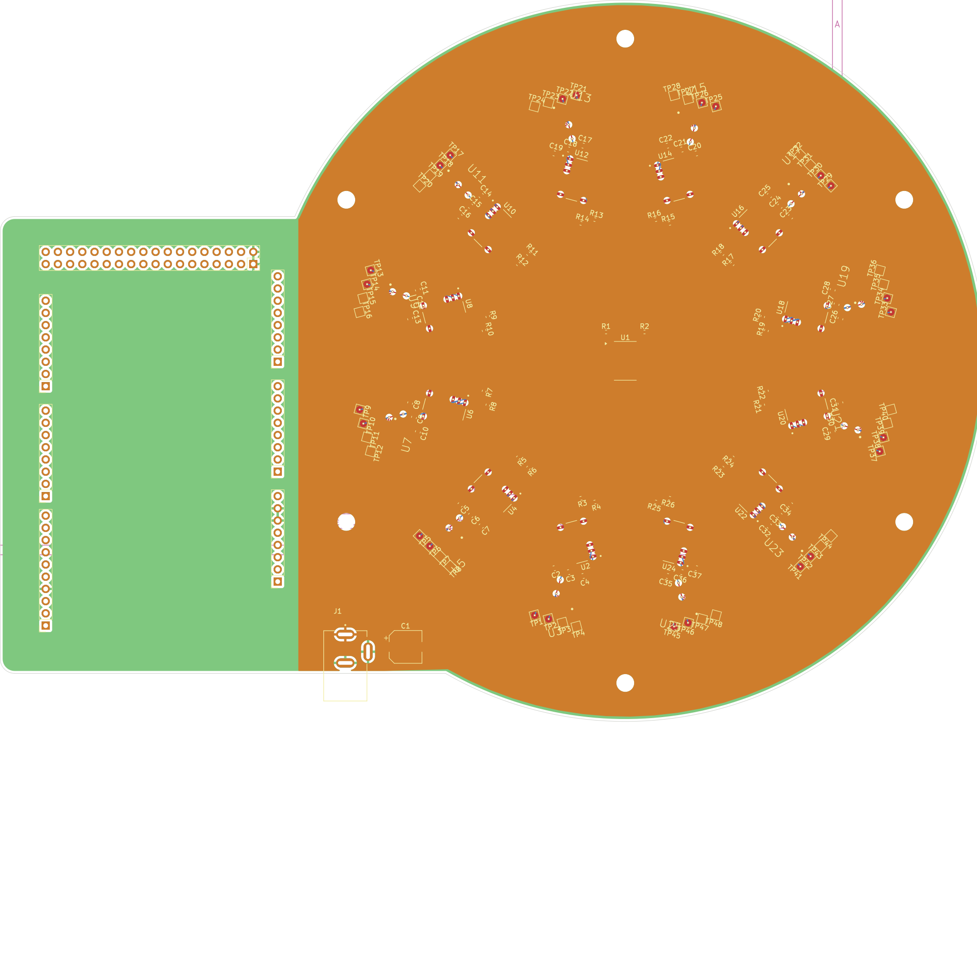
4 layers227.8 × 132.5 mm

 nagapi2357-ui/Prime_Maxel-v3
V3 torsion ring PCB — original experiment showed apparent prime-ratio advantages, but a subsequent pre-registered replication (Plan C, pure sine waves) returned null on 7/8 metrics. V3 effects attributed to square-wave harmonic confound. See CORRIGENDUM. KiCad 9.
Prime Maxel v3 is an open-source printed circuit board by nagapi2357-ui, from the nagapi2357-ui/Prime_Maxel-v3 repository on GitHub. It is a 4-layer board of 201.2 × 95 mm with 150 parts on 331 nets, routed with 384 tracks and 240 vias.
It is built around the SLG47004V and EJ503A. Its parts include 37 capacitors, 26 resistors, 25 ICs and 8 connectors.
⚠️ CORRIGENDUM (19 September 2026): The results reported below have not been reproduced in a subsequent pre-registered replication experiment (Plan C) using pure sine waves. Seven of eight metrics returned null; the original effects are attributed to a harmonic confound from square-wave signal generation. See the full corrigendum for details. The original data and claims are preserved below for transparency.
First experimental evidence that prime-ratio frequency networks outperform composite-ratio networks in a physical resonator.
Published: Zenodo DOI 10.5281/zenodo.20637347
Prime_Maxel-v3 is a 12-cell torsion resonator ring built to test whether prime-ratio frequency relationships produce measurably different coupling behaviour compared to composite ratios. Each cell pairs a SLG47004V GreenPAK mixed-signal IC with an LM324 op-amp, connected via twin shared copper torsion traces on a 4-layer PCB fabricated by JLCPCB. An Arduino Mega 2560 generates six independent square-wave channels using Timer1, fed into the ring through bodge wires. Output is captured on a Rigol DS1054Z oscilloscope and processed through a Python analysis pipeline.
Fifteen distinct frequency sets were tested across prime, composite, Fibonacci, zeta-zero, and coprimality configurations — producing the Four-Factor Theory of resonator coupling.
⚠️ These results have not been reproduced under controlled conditions. The effects are most likely due to odd-harmonic content in the square-wave signals, not the arithmetic properties of the frequency ratios. A pre-registered replication using pure sine waves returned null on amplitude, coherence, and cross-correlation.
| Top | Bottom |
|---|---|
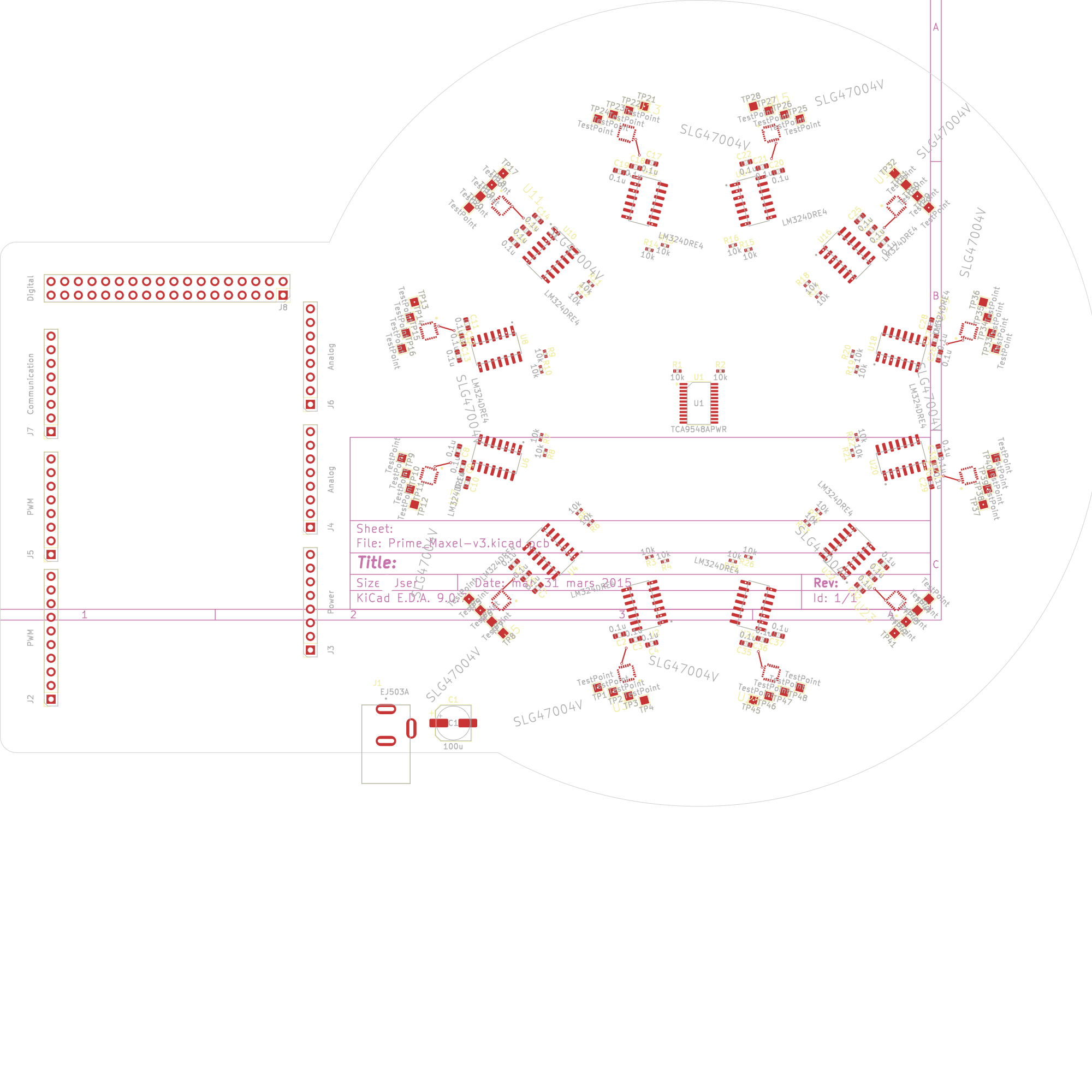 | 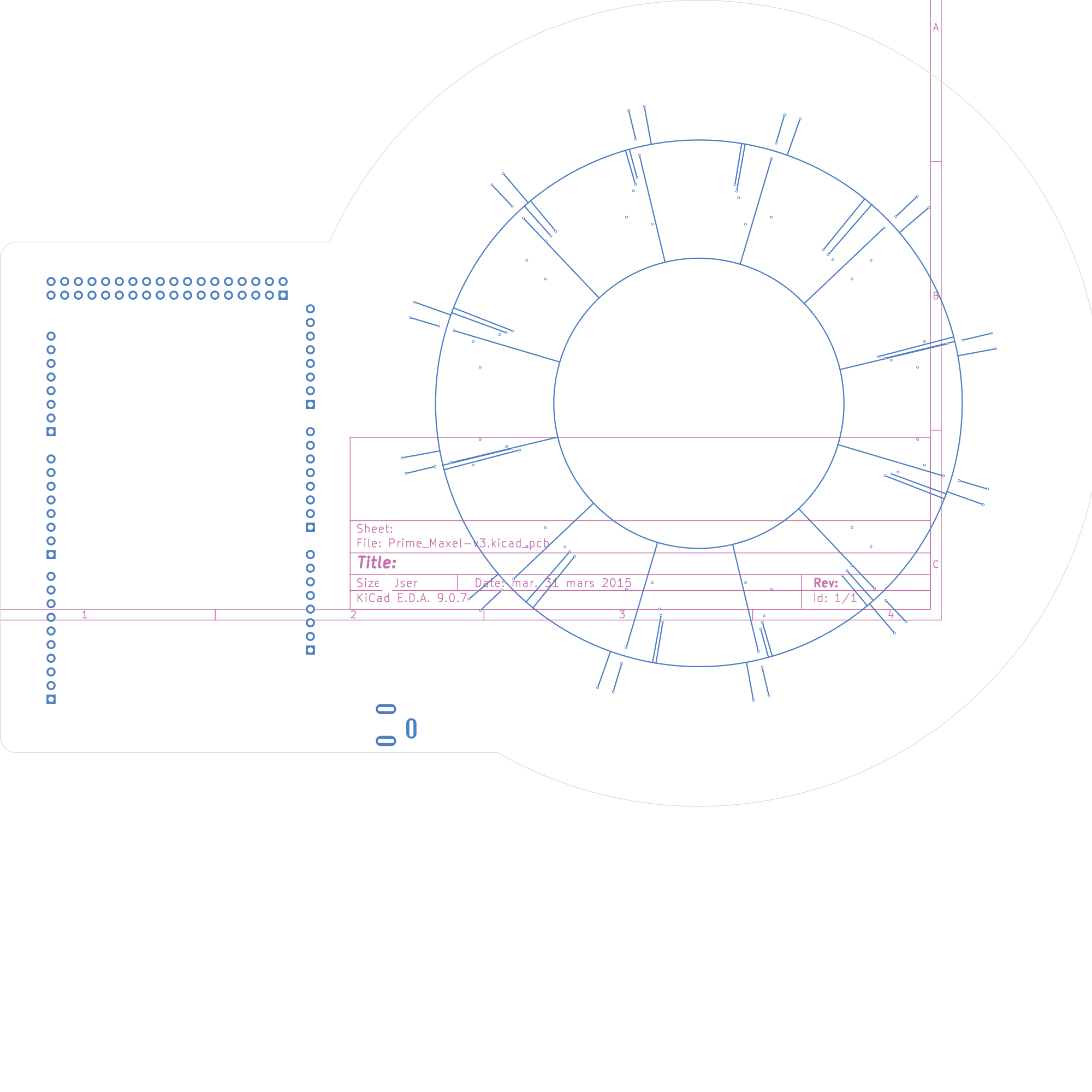 |
Arduino Mega (Timer1) → 6× square-wave channels → bodge wires
    ↓
12× cells (SLG47004V + LM324) in circular ring
    ↓
TORSION_A (498 mm) / TORSION_B (601 mm) shared copper traces
    ↓
Rigol DS1054Z → Python analysis pipelinearduino/ — All Arduino sketches (prime, composite, zeta zero, progressive, coprimality experiments, etc.)Nagaπ Python Scripts/ — Analysis pipeline (rigol_capture.py, torsion_analyze.py, experiment_suite_analysis.py)research/ — Experimental results, detailed write-ups per experiment, and the published paperLTspice_Sim/ — SPICE simulations of the golden cell circuitGo Configure/ — GreenPAK configuration filesdocs/ — Board rendersLibraries/ — Custom KiCad symbols and footprintsSee LICENSE for details.
Adrian Sutton — Tusk Innovations
AI Research Contributor: Nagaπ
| Qty | Value | Footprint | References |
|---|---|---|---|
| 48 | TestPoint | TestPoint:TestPoint_Pad_1.5x1.5mm | TP1, TP2, TP10, TP11, TP12, TP13, TP14, TP15, TP16, TP17, TP18, TP19, TP20, TP21, TP22, TP23 +32 |
| 36 | 0.1u | Capacitor_SMD:C_0603_1608Metric | C2, C10, C11, C12, C13, C14, C15, C16, C17, C18, C19, C20, C21, C22, C23, C24 +20 |
| 26 | 10k | Resistor_SMD:R_0402_1005Metric | R1, R2, R10, R11, R12, R13, R14, R15, R16, R17, R18, R19, R20, R21, R22, R23 +10 |
| 12 | LM324DRE4 | Adrian:LM324DRE4-SOIC127P600X175-14N | U2, U4, U6, U8, U10, U12, U14, U16, U18, U20, U22, U24 |
| 12 | SLG47004V | Adrian:SLG47004V-STQFN-24-3.0X3.0-A | U3, U5, U7, U9, U11, U13, U15, U17, U19, U21, U23, U25 |
| 6 | MountingHole_3.2mm | Arduino_MountingHole:MountingHole_3.2mm | MH1, MH2, MH3, MH4, MH5, MH6 |
| 2 | Analog | Connector_PinSocket_2.54mm:PinSocket_1x08_P2.54mm_Vertical | J4, J6 |
| 1 | 100u | Capacitor_SMD:CP_Elec_6.3x7.7 | C1 |
| 1 | Communication | Connector_PinSocket_2.54mm:PinSocket_1x08_P2.54mm_Vertical | J7 |
| 1 | Digital | Connector_PinSocket_2.54mm:PinSocket_2x18_P2.54mm_Vertical | J8 |
| 1 | EJ503A | Adrian:MPD_EJ503A | J1 |
| 1 | PWM | Connector_PinSocket_2.54mm:PinSocket_1x08_P2.54mm_Vertical | J5 |
| 1 | PWM | Connector_PinSocket_2.54mm:PinSocket_1x10_P2.54mm_Vertical | J2 |
| 1 | Power | Connector_PinSocket_2.54mm:PinSocket_1x08_P2.54mm_Vertical | J3 |
| 1 | TCA9548APWR | Package_SO:TSSOP-24_4.4x7.8mm_P0.65mm | U1 |


vishalsaravanan-k/home-automation-using-esp32-and-relay
This project is a basic home automation system built using an ESP32, capable of turning appliances ON/OFF through both mobile app (via Wi-Fi) and an IR remote.


r-map/rmap
rete monitoraggio ambientale partecipativo documentation at https://doc.rmap.cc

atopile/swoop
With swoop, you can fly remote controlled aircraft with the motion of your hand. It's especially fun when flying FPV because the motion of your remote precisely maps to the aircraft.
It measures 201.2 × 95 mm and has 4 copper layers, 1.6 mm thick.
150 parts, built around the SLG47004V and EJ503A. The full list of its parts is on this page, with links to each part's symbol and footprint where PCBKit's library has them.
From the nagapi2357-ui/Prime_Maxel-v3 repository on GitHub, at the commit this page was made from: the board is Prime_Maxel-v3.kicad_pcb and its schematic Prime_Maxel-v3.kicad_sch. PCBKit opens the board in the browser, with nothing to install.
Its repository states no licence, so its author keeps all rights: ask nagapi2357-ui before reusing the design.