2 layers105 × 58 mm
ZAP-01A
ponrajleo/AI-Hardware-ESP32S3-
This project is part of a complete open-source hardware design course on YouTube:
103 parts

 mynameisbrozu/esp32-based-iot-switch
Personal project - Iot switch with esp32c5 and 3.7" epaper display
ESP32C5 iot switch is an open-source printed circuit board by mynameisbrozu, from the mynameisbrozu/esp32-based-iot-switch repository on GitHub, published under the MIT licence. It is a 2-layer board of 200.3 × 96 mm with 89 parts on 71 nets, routed with 477 tracks and 870 vias.
It is built around the ESP32-C5-WROOM-1-N16R8, HLK-5M05 and TTP223-BA6, with the SPX3819M5-L-3-3, USBLC6-2SC6 and MBR0530 among its other parts. Its parts include 24 capacitors, 15 resistors, 10 diodes, 5 connectors and 4 ICs. It belongs with the lEDs and displays and home automation and IoT boards and the ESP32 and RISC-V boards of this library.


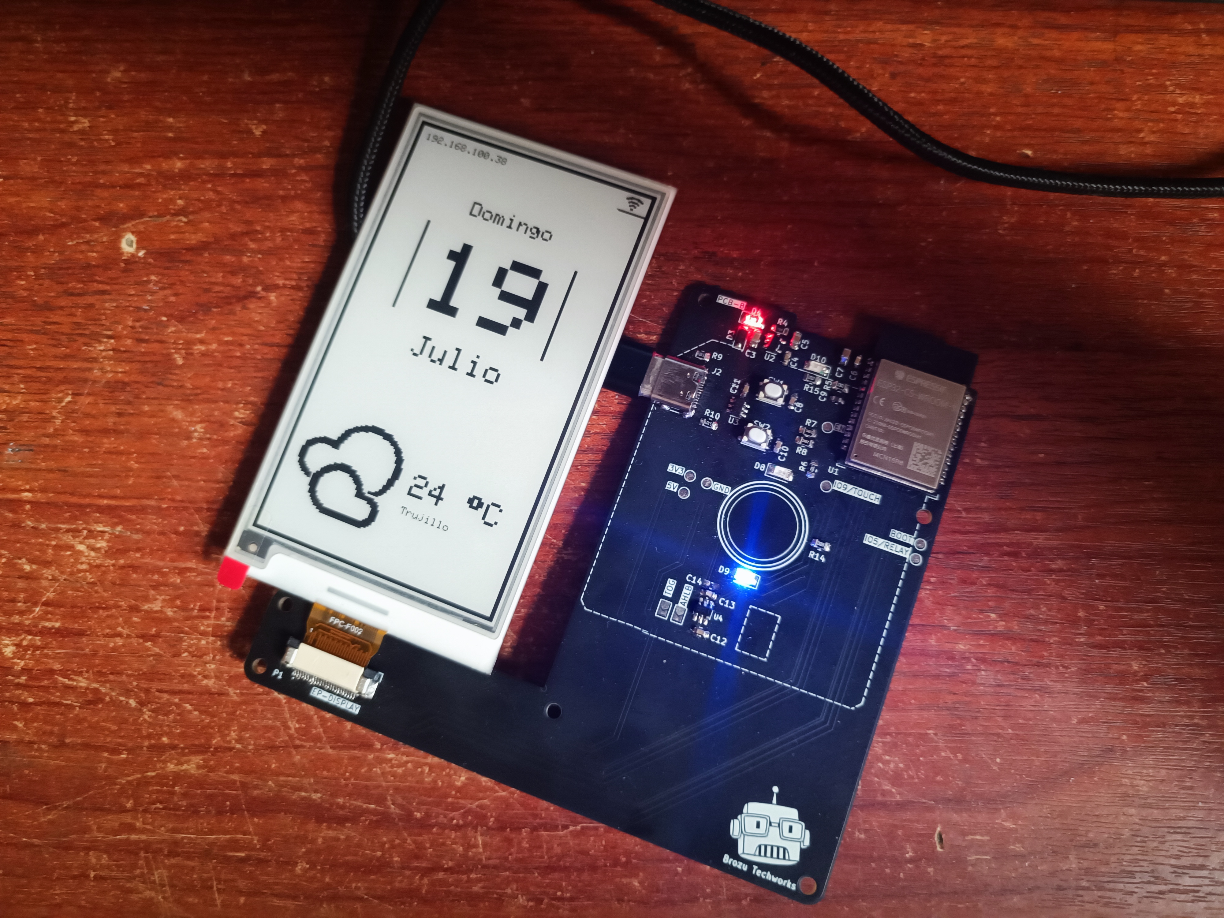
An IOT switch designed in KiCad based on ESP32-C5 and GDEY037T03 e-paper display. All electronic components were sourced from AliExpress (wanted to try something I guess).
32-bit single-core RISC-V MCU running at up to 240 MHz with 29 GPIOs.
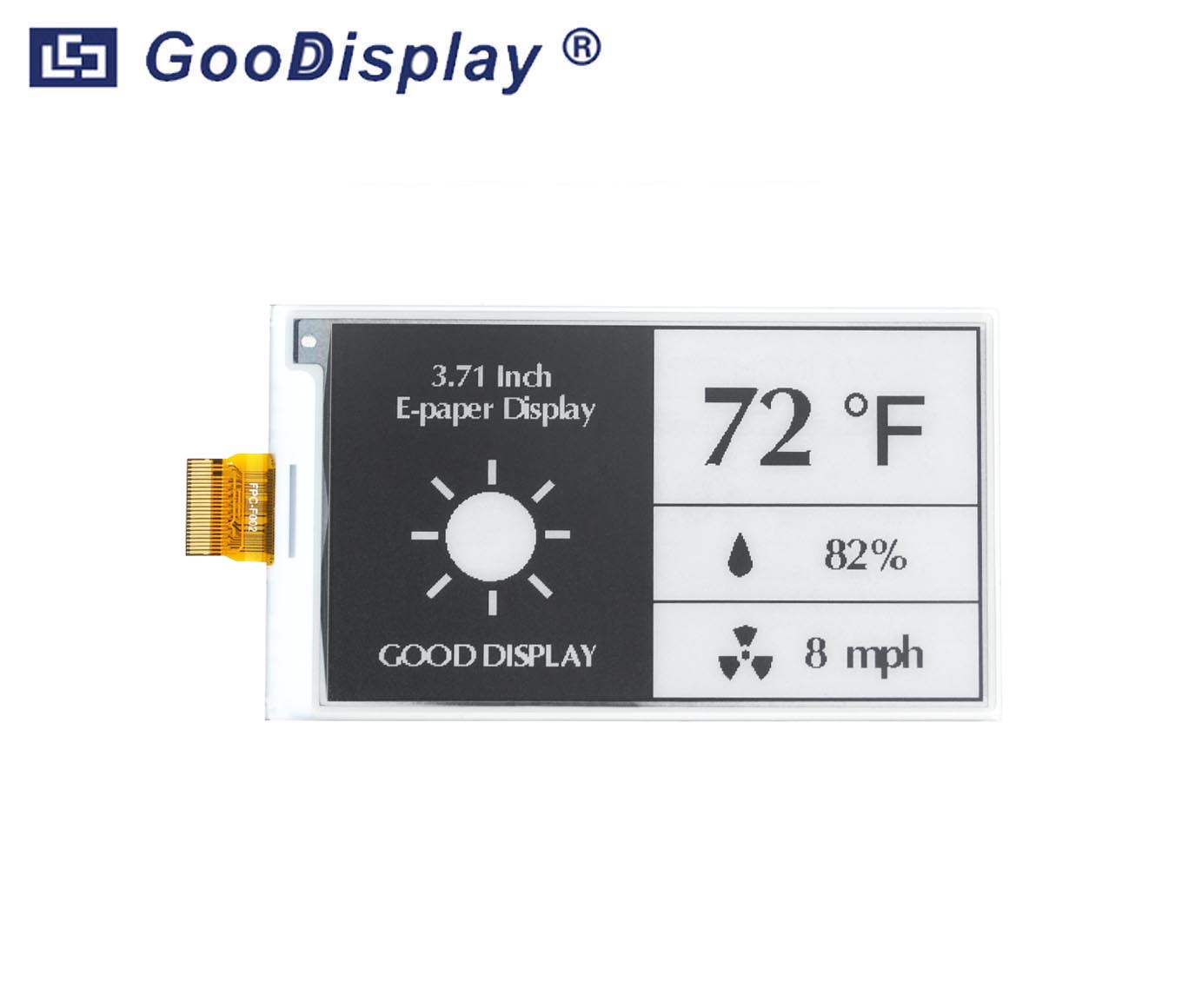
3.7" black-and-white e-paper display.
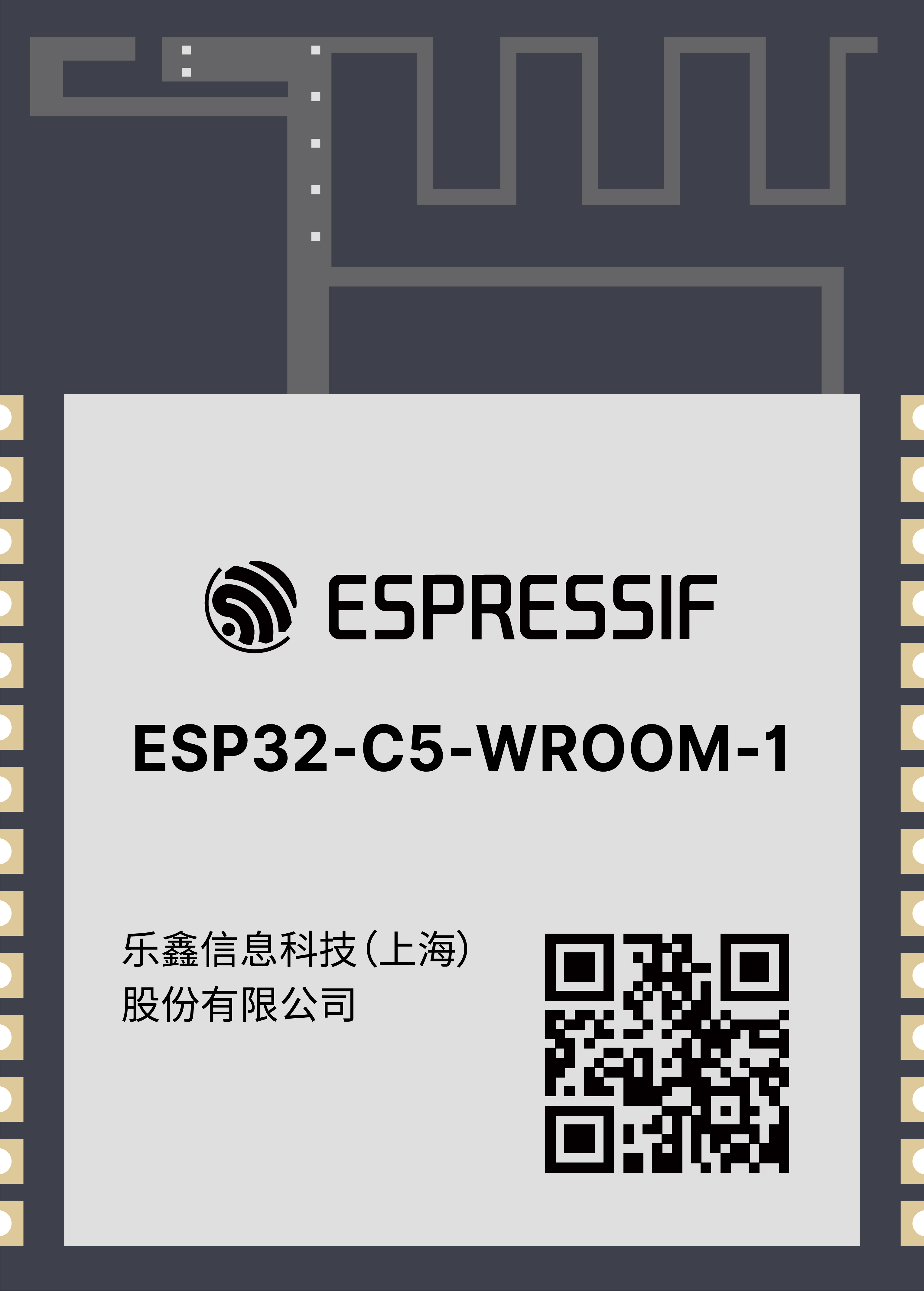
All components used in this project were sourced from AliExpress.
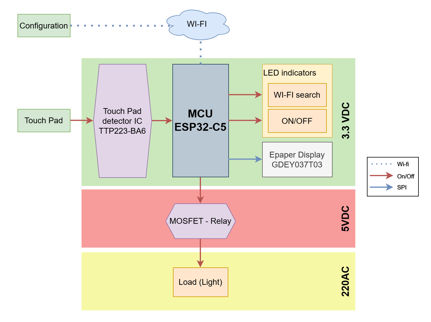
A simple system block diagram was created early in the design process to estimate the power budget and guide component selection.
The BOM was progressively refined while developing the schematic. BOM in "spreadsheets" folder.
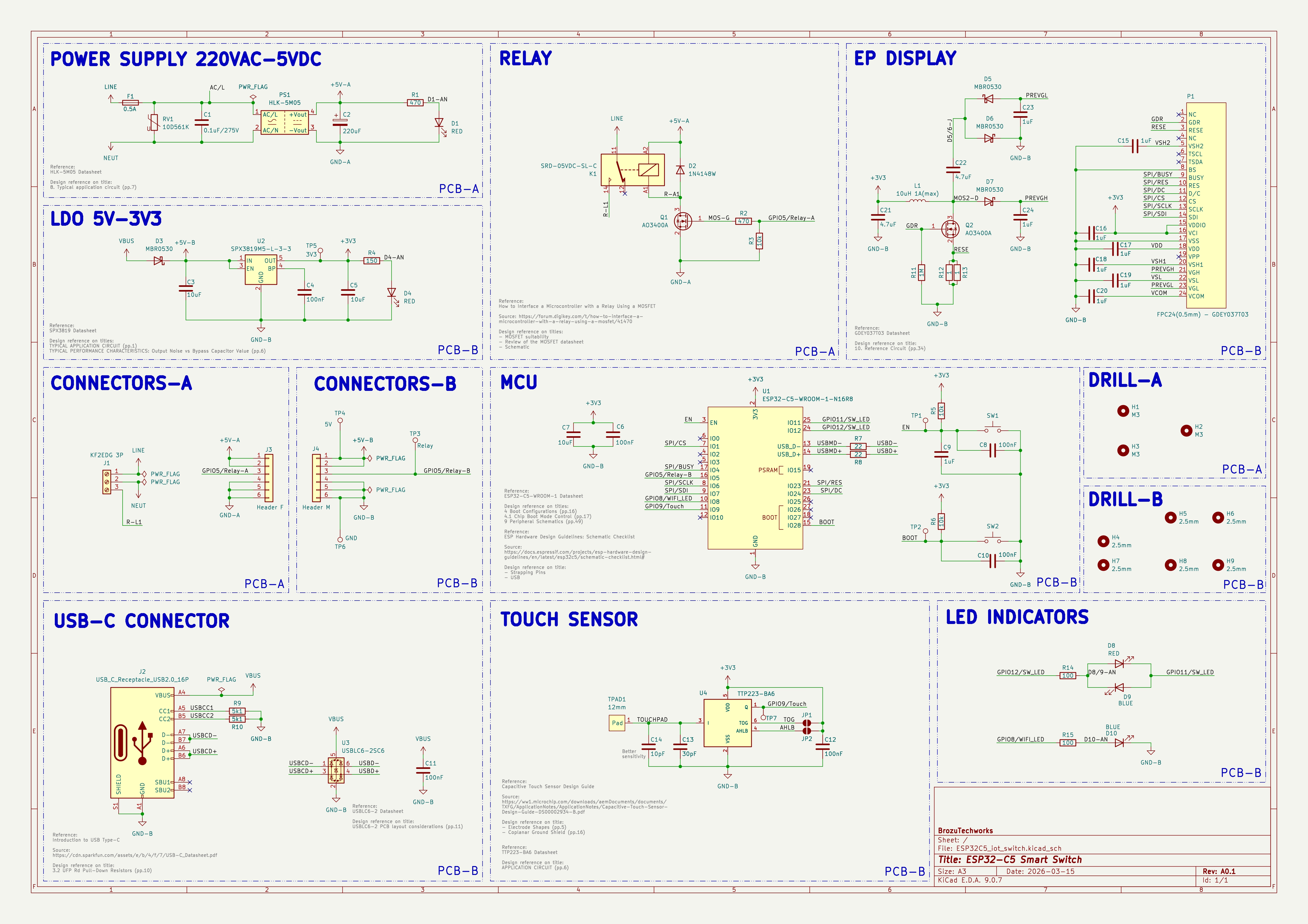
The schematic was designed using reference circuits from datasheets, application notes, and technical articles.
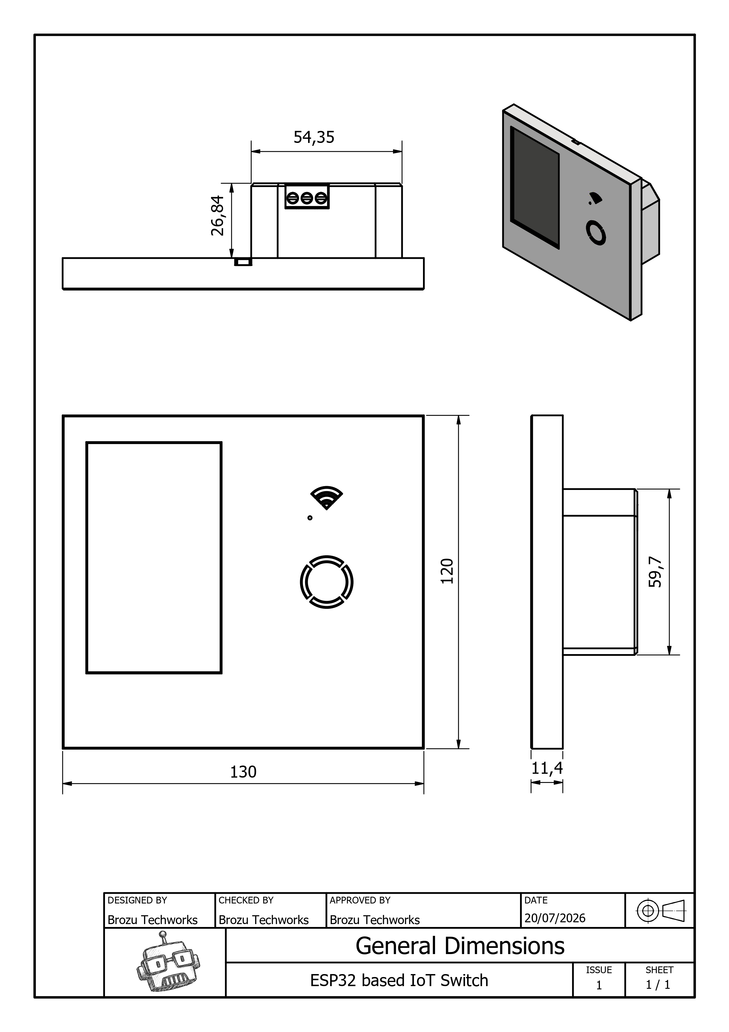
The PCB layout shows some of the mechanical constraints of the enclosure.
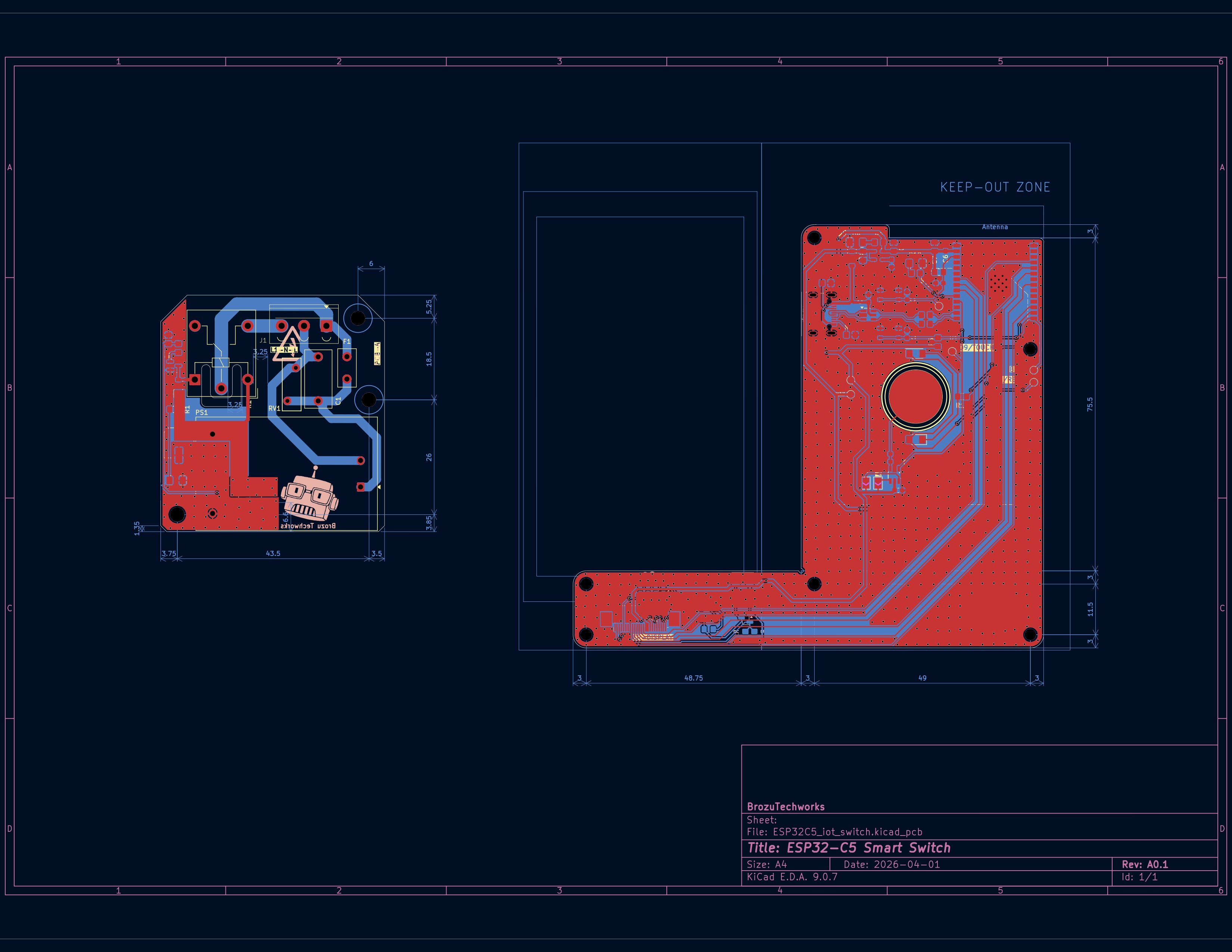
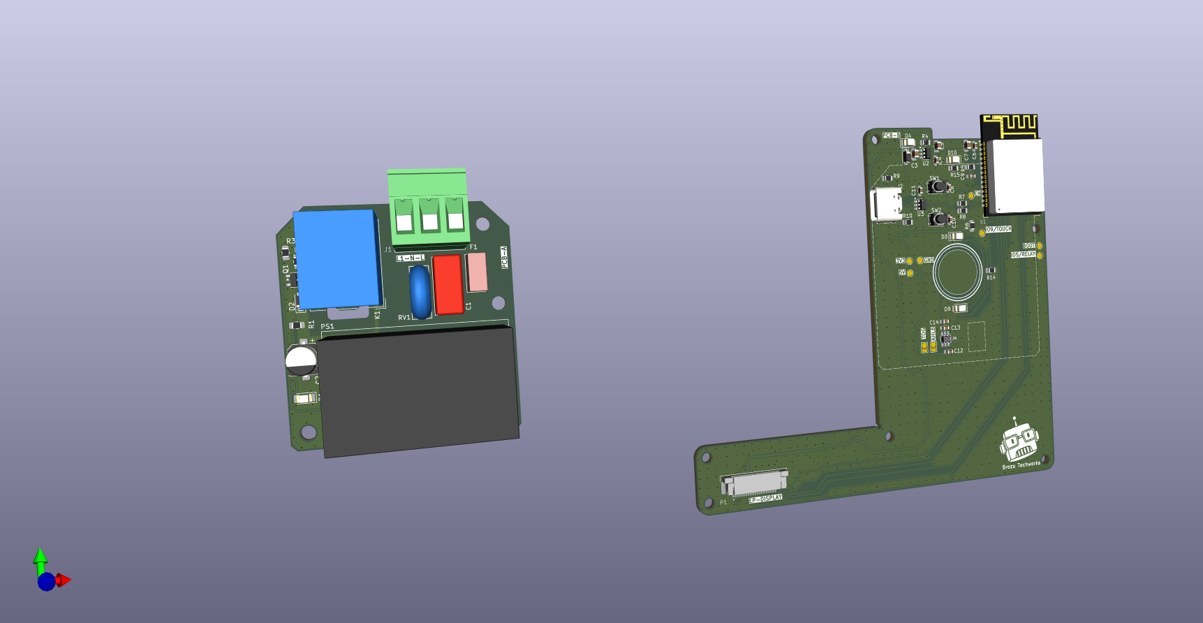 | 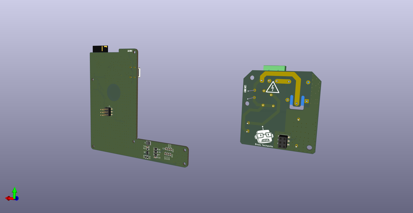 |
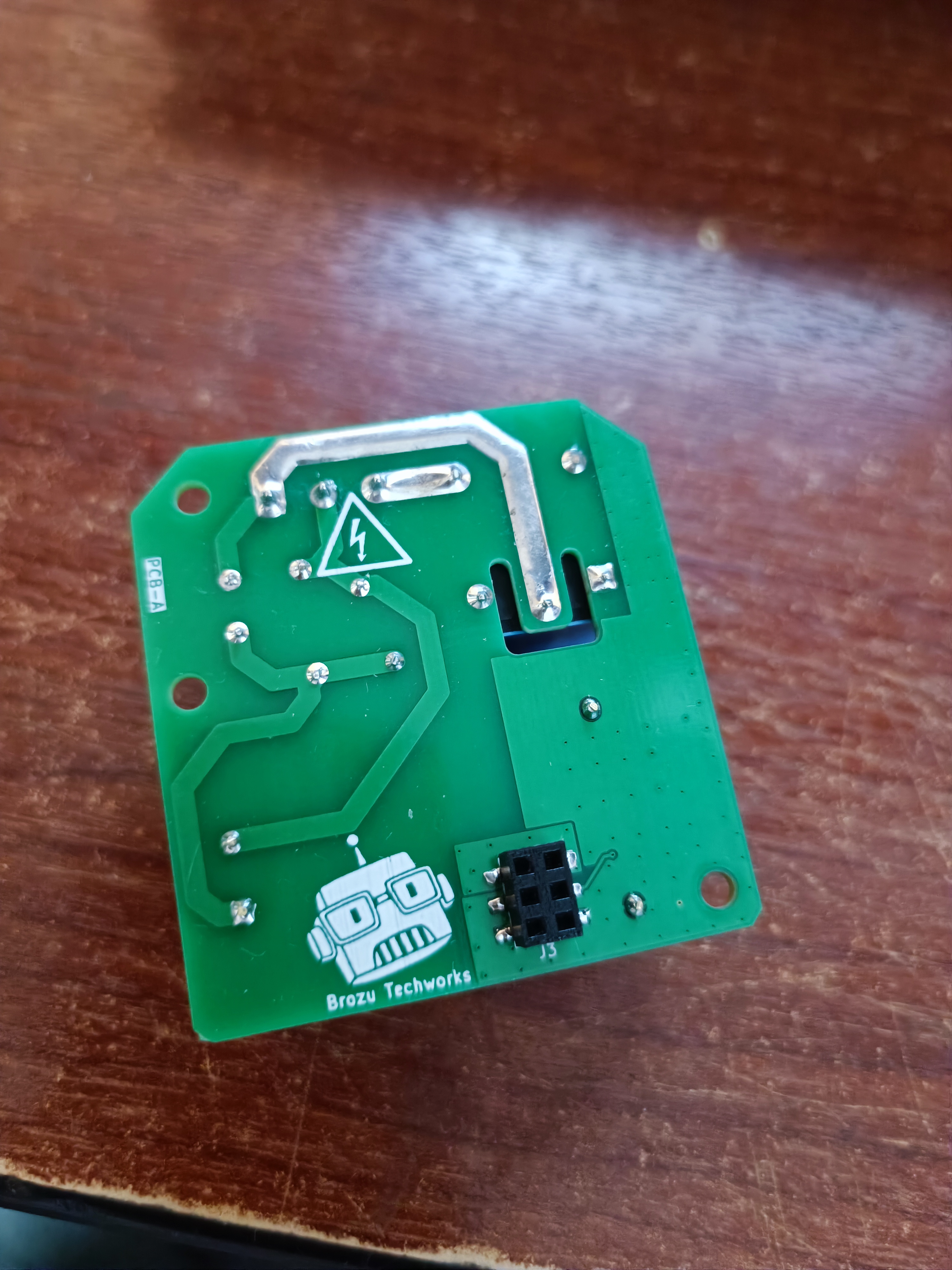
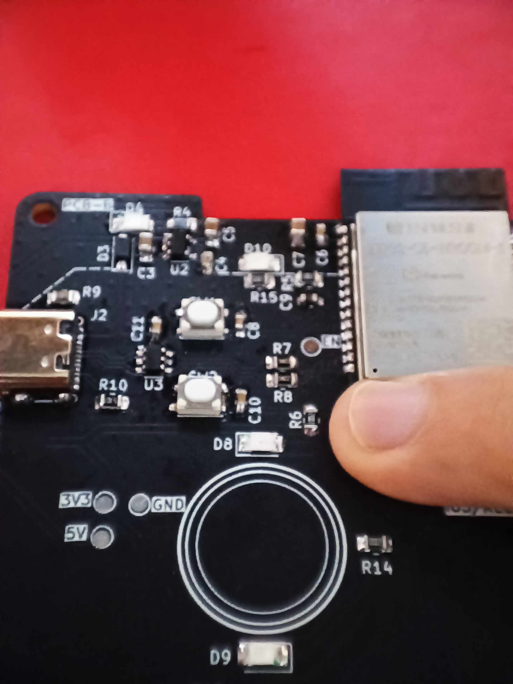
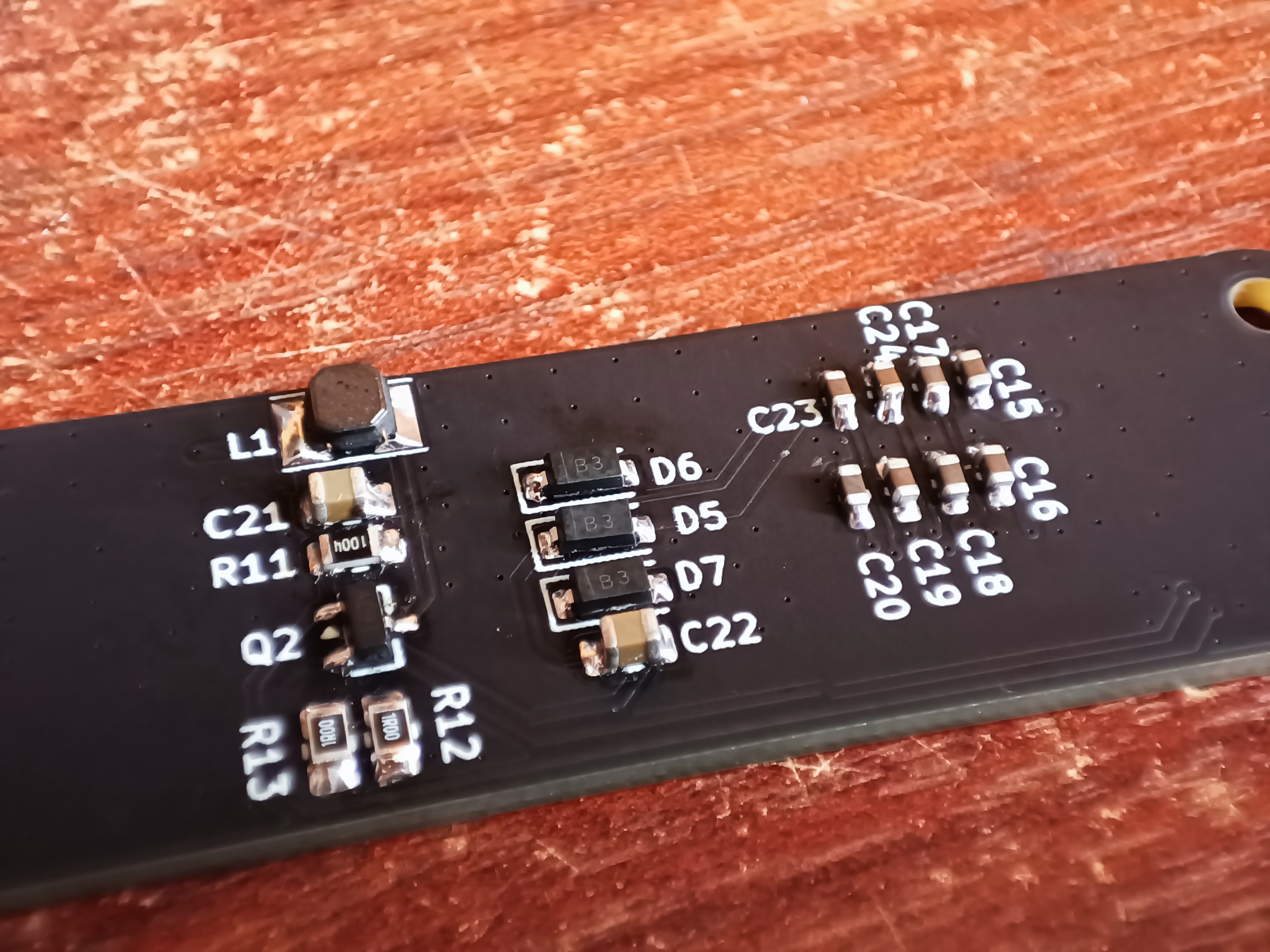
All components were manually assembled and soldered with a soldering iron (yeah...).
PCB-A
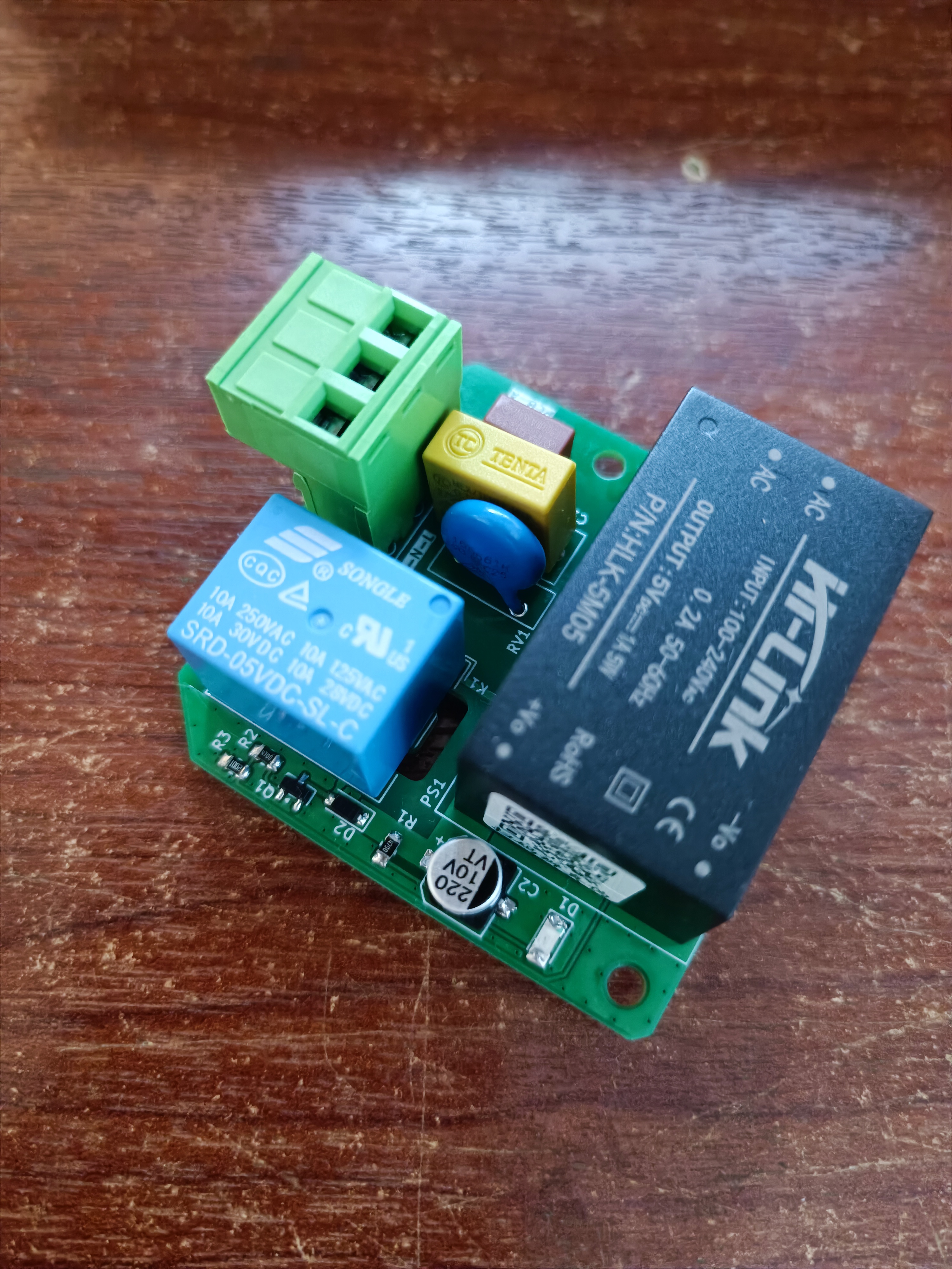 |  |
PCB-B
 |  |
Firmware development started with the development of an integration library between the GDEY037T03 e-paper display and the Adafruit GFX library
The library can currently be found on https://github.com/mynameisbrozu/GDEY037T03-AdafruitGFX.
Features:
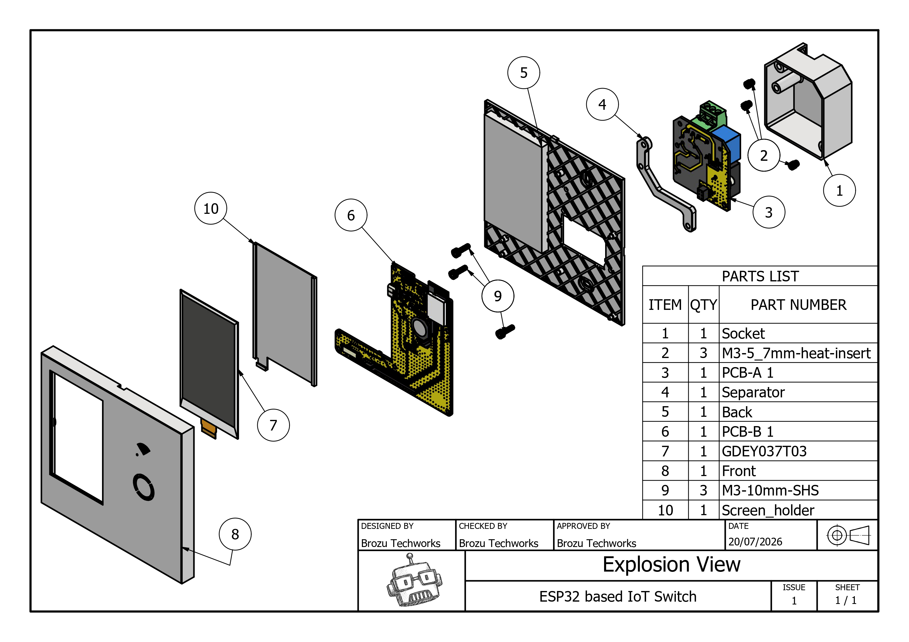
The enclosure was designed in Autodesk Inventor. Documentation, assembly instructions, and design notes are still in progress and will be added soon.
| Qty | Value | Footprint | References |
|---|---|---|---|
| 9 | 1uF | Capacitor_SMD:C_0603_1608Metric_Pad1.08x0.95mm_HandSolder | C9, C15, C16, C17, C18, C19, C20, C23, C24 |
| 6 | 100nF | Capacitor_SMD:C_0603_1608Metric_Pad1.08x0.95mm_HandSolder | C4, C6, C8, C10, C11, C12 |
| 6 | 2.5mm | MountingHole:MountingHole_2.5mm | H4, H5, H6, H7, H8, H9 |
| 4 | MBR0530 | Diode_SMD:D_SOD-123 | D3, D5, D6, D7 |
| 3 | 10k | Resistor_SMD:R_0805_2012Metric_Pad1.20x1.40mm_HandSolder | R3, R5, R6 |
| 3 | 10uF | Capacitor_SMD:C_0805_2012Metric_Pad1.18x1.45mm_HandSolder | C3, C5, C7 |
| 3 | LOGO | LOGO | G***, G***, G*** |
| 3 | M3 | MountingHole:MountingHole_3.2mm_M3 | H1, H2, H3 |
| 3 | RED | LED_SMD:LED_1206_3216Metric_Pad1.42x1.75mm_HandSolder | D1, D4, D8 |
| 2 | 1 | Resistor_SMD:R_0805_2012Metric_Pad1.20x1.40mm_HandSolder | R12, R13 |
| 2 | 100 | Resistor_SMD:R_0805_2012Metric_Pad1.20x1.40mm_HandSolder | R14, R15 |
| 2 | 22 | Resistor_SMD:R_0805_2012Metric_Pad1.20x1.40mm_HandSolder | R7, R8 |
| 2 | 3*4*2,5mm | Button_Switch_SMD:SW_SPST_PTS810 | SW1, SW2 |
| 2 | 4.7uF | Capacitor_SMD:C_0805_2012Metric_Pad1.18x1.45mm_HandSolder | C21, C22 |
| 2 | 470 | Resistor_SMD:R_0805_2012Metric_Pad1.20x1.40mm_HandSolder | R1, R2 |
| 2 | 5k1 | Resistor_SMD:R_0805_2012Metric_Pad1.20x1.40mm_HandSolder | R9, R10 |
| 2 | AO3400A | Package_TO_SOT_SMD:SOT-23 | Q1, Q2 |
| 2 | BLUE | LED_SMD:LED_1206_3216Metric_Pad1.42x1.75mm_HandSolder | D9, D10 |
| 2 | SolderJumper_2_Open | Jumper:SolderJumper-2_P1.3mm_Open_TrianglePad1.0x1.5mm | JP1, JP2 |
| 1 | 0.1uF/275V | Capacitor_THT:C_Rect_L13.0mm_W6.0mm_P10.00mm_FKS3_FKP3_MKS4 | C1 |
| 1 | 0.5A | Fuse:Fuse_Littelfuse_395Series | F1 |
| 1 | 10D561K | Varistor:RV_Disc_D12mm_W4.3mm_P7.5mm | RV1 |
| 1 | 10pF | Capacitor_SMD:C_0603_1608Metric_Pad1.08x0.95mm_HandSolder | C14 |
| 1 | 10uH 1A(max) | Inductor_SMD:L_Taiyo-Yuden_NR-30xx_HandSoldering | L1 |
| 1 | 12mm | capacitive_pad:touch_pad12mm | TPAD1 |
| 1 | 150 | Resistor_SMD:R_0805_2012Metric_Pad1.20x1.40mm_HandSolder | R4 |
| 1 | 1M | Resistor_SMD:R_0805_2012Metric_Pad1.20x1.40mm_HandSolder | R11 |
| 1 | 1N4148W | Diode_SMD:D_SOD-123 | D2 |
| 1 | 220uF | Capacitor_SMD:CP_Elec_6.3x5.4 | C2 |
| 1 | 30pF | Capacitor_SMD:C_0603_1608Metric_Pad1.08x0.95mm_HandSolder | C13 |
| 1 | 3V3 | TestPoint:TestPoint_Pad_D1.5mm | TP5 |
| 1 | 5V | TestPoint:TestPoint_Pad_D1.5mm | TP4 |
| 1 | BOOT | TestPoint:TestPoint_Pad_D1.5mm | TP2 |
| 1 | EN | TestPoint:TestPoint_Pad_D1.5mm | TP1 |
| 1 | ESP32-C5-WROOM-1-N16R8 | ESP32-C5-WROOM-1:ESP32-C5-WROOM-1 | U1 |
| 1 | FPC24(0.5mm) - GDEY037T03 | Mintron_FPC_LW05201:FPC_LW05201-24 | P1 |
| 1 | GND | TestPoint:TestPoint_Pad_D1.5mm | TP6 |
| 1 | HLK-5M05 | Converter_ACDC:Converter_ACDC_Hi-Link_HLK-5Mxx | PS1 |
| 1 | Header F | Connector_PinSocket_2.54mm:PinSocket_2x03_P2.54mm_Vertical_SMD | J3 |
| 1 | Header M | Connector_PinHeader_2.54mm:PinHeader_2x03_P2.54mm_Vertical_SMD | J4 |
| 1 | KF2EDG 3P | TerminalBlock_Degson:TerminalBloc_2EDGV-2EDGK_5.08mm_01x03P | J1 |
| 1 | Relay | TestPoint:TestPoint_Pad_D1.5mm | TP3 |
| 1 | SPX3819M5-L-3-3 | Package_TO_SOT_SMD:SOT-23-5 | U2 |
| 1 | SRD-05VDC-SL-C | Relay_THT:Relay_SPDT_Hongfa_HF3F-L-xx-1ZL1T | K1 |
| 1 | TTP223-BA6 | TTP223-BA6:SOT23-6 | U4 |
| 1 | Touch | TestPoint:TestPoint_Pad_D1.5mm | TP7 |
| 1 | USBLC6-2SC6 | Package_TO_SOT_SMD:SOT-23-6 | U3 |
| 1 | USB_C_Receptacle_USB2.0_16P | Connector_USB:USB_C_Receptacle_GCT_USB4105-xx-A_16P_TopMnt_Horizontal | J2 |
ponrajleo/AI-Hardware-ESP32S3-
This project is part of a complete open-source hardware design course on YouTube:

ajkumar-1907/POWER-ELECTRONICS-LIB
Open-source library of power electronics converter topologies — KiCad schematics, working principles, use cases, and design notes for DC-DC, AC-DC, DC-AC, and AC-AC converters. Free to use, modify, and build on.

freezweb/de.freezweb.heizungssteuerung
Dieses Verzeichnis enthaelt den KiCad-Startentwurf fuer die dezentrale Pumpengruppen-Platine:

lalithk06/Esp32_Smart_Plug
Hardware reference design for an ESP32-S3 smart plug with mains power conversion, relay switching, RTC support, USB connectivity, and protection components.

VikramR3/ViRa_Ai_plug
ESP32-S3 mains smart plug: HLK-5M05 isolated supply, SRD-05VDC relay, DS3231M RTC. 2-layer KiCad design.

rgodin974/ESP32_sprinkler_timer
Coded on PlateformIO and VS Code. Project based on RitonDuino : https://riton-duino.blogspot.com/2023/08/esp32-micro-irrigation-connectee-partie.html


It measures 200.3 × 96 mm and has 2 copper layers, 1.6 mm thick.
89 parts, built around the ESP32-C5-WROOM-1-N16R8, HLK-5M05, TTP223-BA6 and SPX3819M5-L-3-3. The full list of its parts is on this page, with links to each part's symbol and footprint where PCBKit's library has them.
From the mynameisbrozu/esp32-based-iot-switch repository on GitHub, at the commit this page was made from: the board is PCB/ESP32C5_iot_switch/ESP32C5_iot_switch.kicad_pcb and its schematic PCB/ESP32C5_iot_switch/ESP32C5_iot_switch.kicad_sch. PCBKit opens the board in the browser, with nothing to install.
Its repository publishes it under the MIT licence: you may reuse it on that licence's terms (keep the author's notice, and for a copyleft licence share your changes alike).