2 layers225 × 356.9 mm
Ferris
pierrechevalier83/ferris
A low profile split keyboard designed to satisfy one single use case elegantly
103 parts1.3k

 mylestunglee/articulation7013
A mechanical keyboard
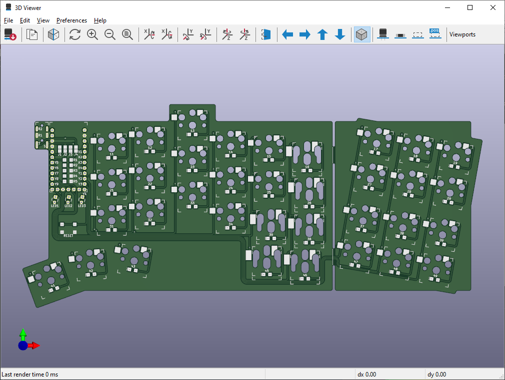
Keyboard is an open-source printed circuit board by mylestunglee, from the mylestunglee/articulation70 repository on GitHub. It is a 2-layer board of 216.5 × 96 mm with 103 parts on 68 nets, routed with 584 tracks and 40 vias.
Its parts include 35 switches, 5 resistors, 3 diodes, 1 IC and 1 connector. It belongs with the keyboards and input boards and the AVR (ATmega, ATtiny) boards of this library.
The articulation70 keyboard is a successor to the articulation80, with LEDs and a more personalised layout.
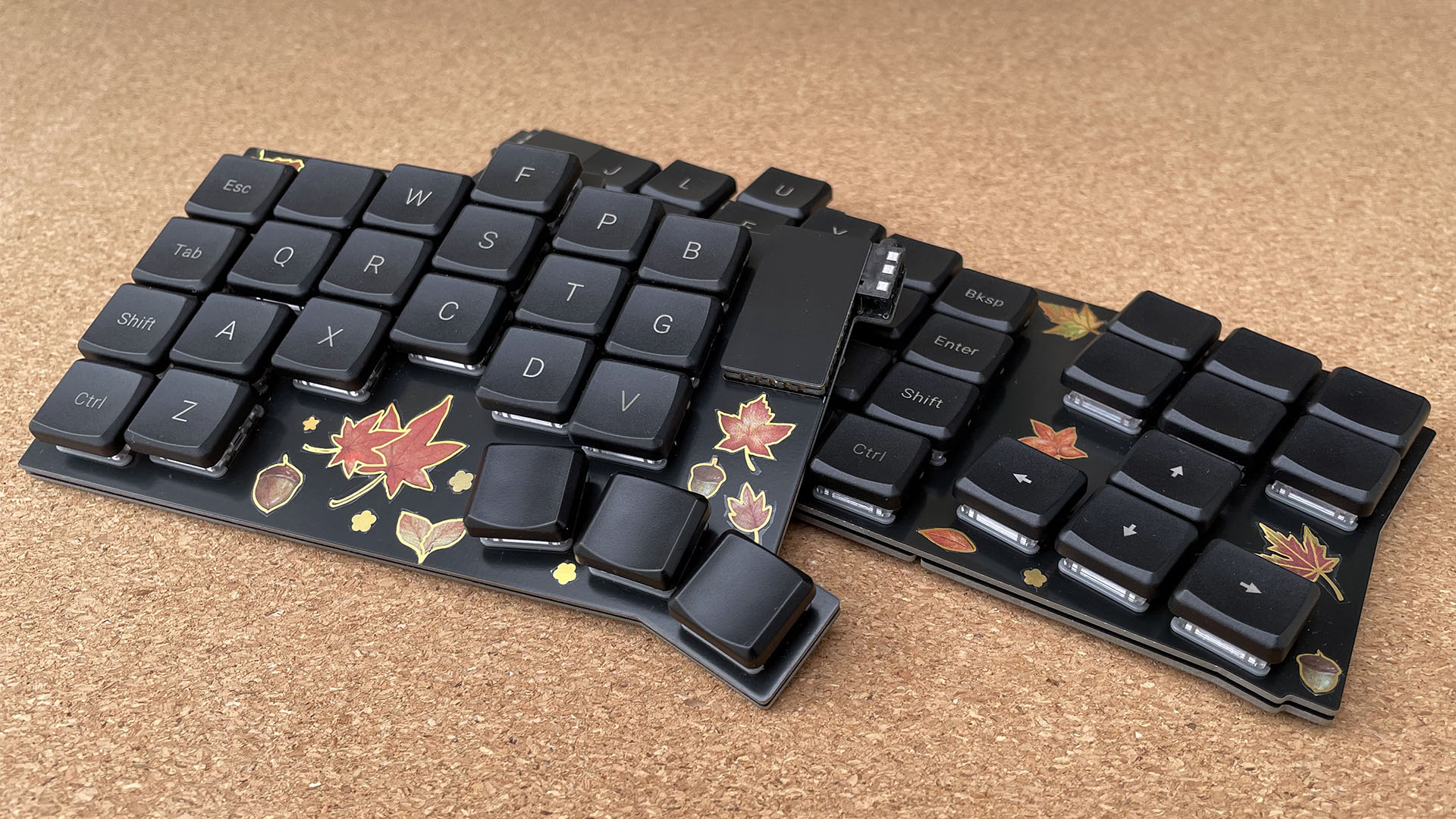
It features:
This repo comes included with two plugins. To install these plugins, copy the directories in plugins into your Plugins Directory, which is found by Tools → External Plugins → Open Plugins Directory in the PCB Editor.
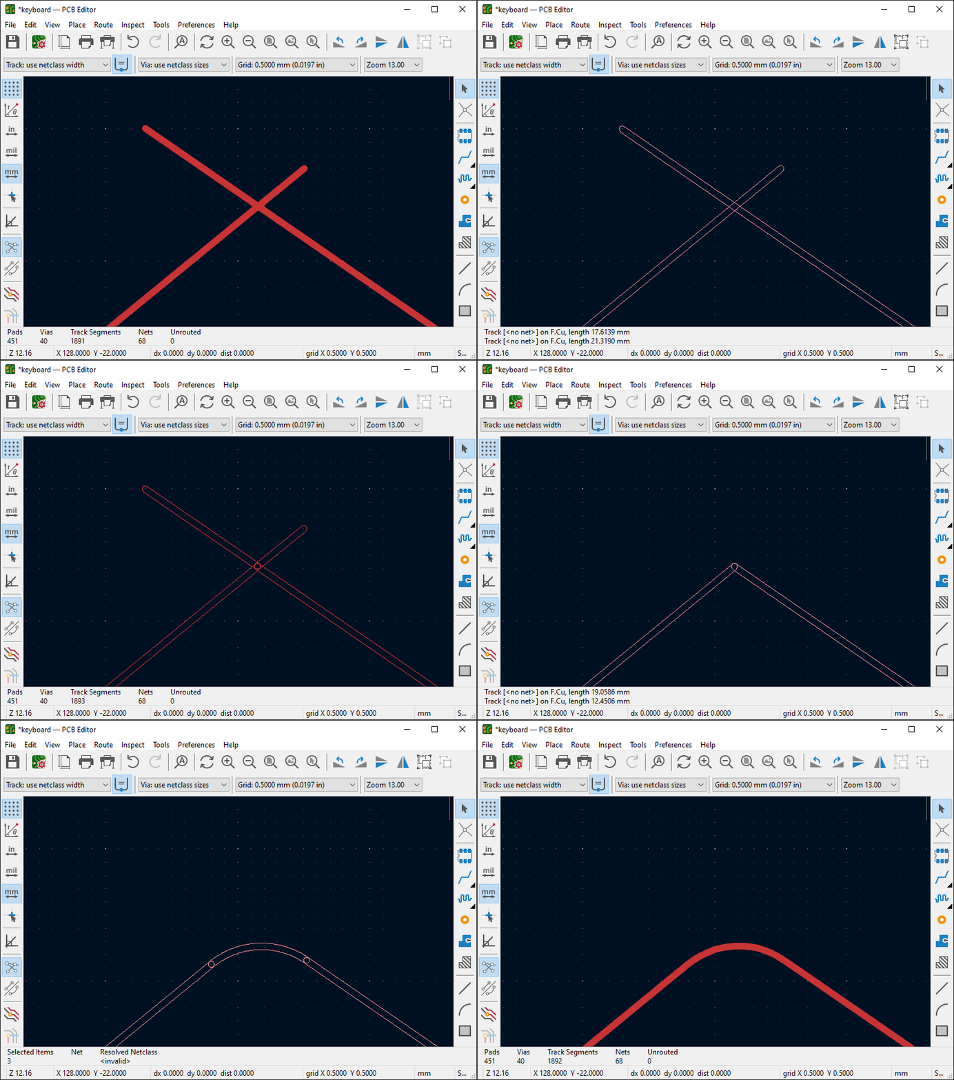
When joining traces from rotated switches, it can be difficult to connect traces from two angles to form a aesthetic curve. This plugins splits two selected intersecting traces into four traces.
An example of use:
Why not?
This build is very similar to many hobby keyboards. Please refer to the instructions for articulation80. You will need a soldering iron.
If using serial, then solder J1, and J4. If using I2C, then solder J2, J3 and J4. Solder on the back of each respective half.
I would recommend substituting for cheaper or easier to source components when possible.
| Component | Quantity | MPN | Purchase Link | Remarks |
|---|---|---|---|---|
| PCB | 2 | |||
| Left switch plate | 1 | |||
| Right switch plate | 1 | |||
| Micro-controller plate | 2 | |||
| Micro-controller | 2 | Elite-C | Link | |
| Through-hole TRRS jack | 2 | PJ-320A | Link | |
| TRRS cable | 1 | Link | Also called a 4-pin 3.5mm audio auxiliary cable | |
| Reset button | 2 | PTS526 SM15 SMTR2 LFS | Link | Different button operating force are possible |
| LED | 3 | HLMP-1401 | Link | Any T1 size |
| 150Ω Resistor | 3 | RC1206FR-07150RL | Link | Optional, for LEDs |
| 4.7kΩ Resistor | 2 | RC1206FR-104K7L | Link | Optional, for I2C connection |
| SMD Diode | 70* | 1N4148W-TP | Link | Any SOD-123 size |
| Hot swap micro-controller sockets | 5 | 315-43-112-41-003000 | Link | Recommended |
| Hot swap pins | 52 | 3320-0-00-15-00-00-03-0 | Link | Recommended |
| Rubber feet | 12** | SJ-5302 CLEAR | Link | |
| Hot swap key sockets | 70* | CPG135001S30 | Link | |
| Key Switch | 70* | CPG135001 | Link | |
| Key Cap | 70* | Ideally different key caps for thumbs | ||
| Stickers | 1 | Link | Optional |
*Adjust for number of keys desired.
**Adjust for number of numpads.
I ordered from JLCPCB, however there are many other manufacturers. Take a look at PCBShopper.
For the PCBs, I used:
For the switch plates, I used:
For the controller plates, I used:
This was tested on installation of FreeCad 0.20.2, Python 3.11.6 and KiCad 7.0.6.
layout.FCStd with FreeCad and open Constants under the model tree view. You should see a spreadsheet of parameters.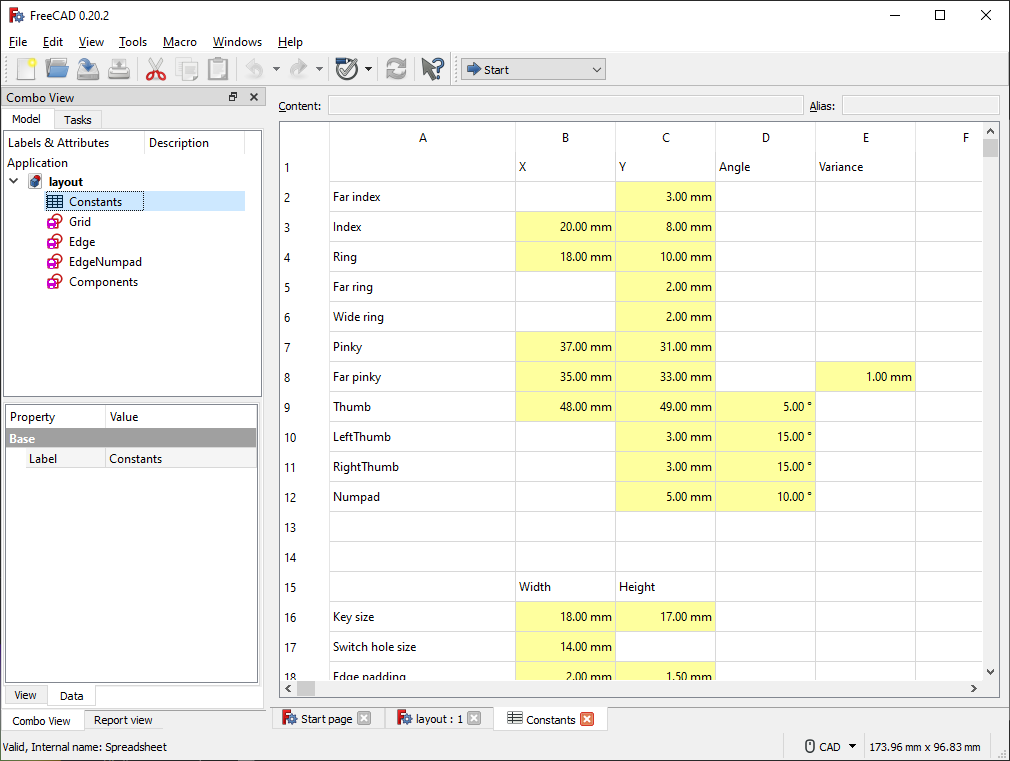
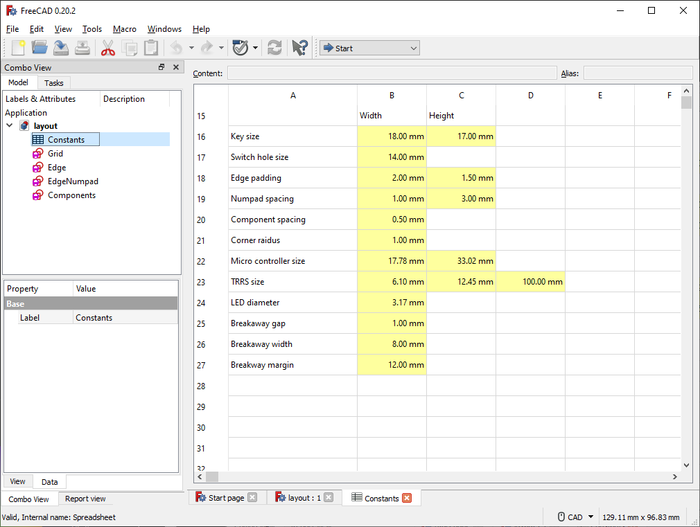
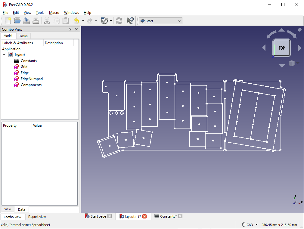
scripts/export_geometry.py into FreeCad's Python console. The console is accessible by View → Panel → Python console. If you get a permission error, change geometry.txt to an absolute path within the repo. You should get a number, which reports the bytes written to geometry.txt.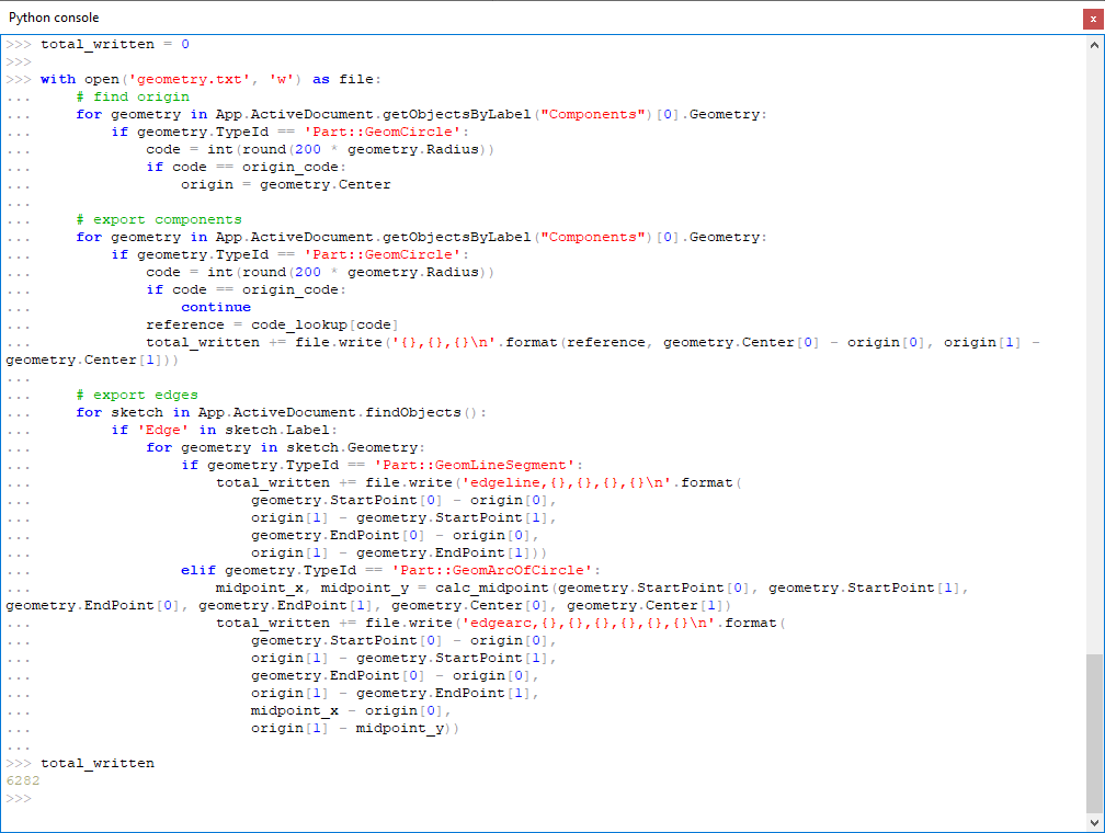
python scripts/update_geometry.py pcb/keyboard.kicad_pcb geometry.txt
python scripts/update_geometry.py left_plate/plate.kicad_pcb geometry.txt
python scripts/update_geometry.py right_plate/plate.kicad_pcb geometry.txt
For now, I will run the first script. Update the PCB files for the plates if desired.
Edge.Cuts layer. The script deletes all previous edges and plots edges in the Edge and EdgeNumpad sketch, which includes construction lines that should not be included in the Edge.Cuts layer. The script also positions footprints according to the Components sketch. The script will output some text because some components' positions are not specified by the layout, such as the resistors.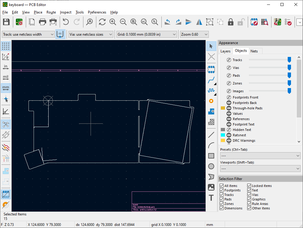
The PCB is ready!
I used QMK program the controllers. To use the same setup as me, copy the contents of qmk directory into your installation of qmk_firmware/keyboards. Flash the left and right controllers with the respective commands:
qmk flash -kb articulation70 -km default -bl dfu-split-left
qmk flash -kb articulation70 -km default -bl dfu-split-right
These commands assume the usage of Elite-C's.
If you want to upgrade the toolchain, you can do so at your own risk:
pacboy update avr-gcc:xscripts/corner_switch_pad_geometry.py
scripts/curved_switch_pad_geometry.pyThese switches generate the geometry for curved pads featured in the switch footprints. The curved shape comes from the rectangular pad subtracted by the clearance of the centre switch drill hole. KiCad supports polygons in pads, but it is not very easy to use. These scripts makes the design of these footprints a bit easier.
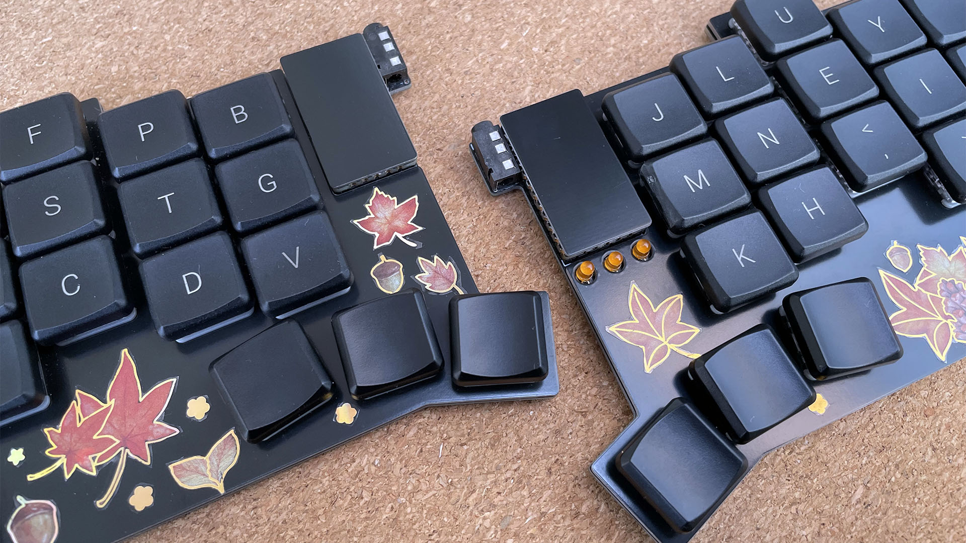
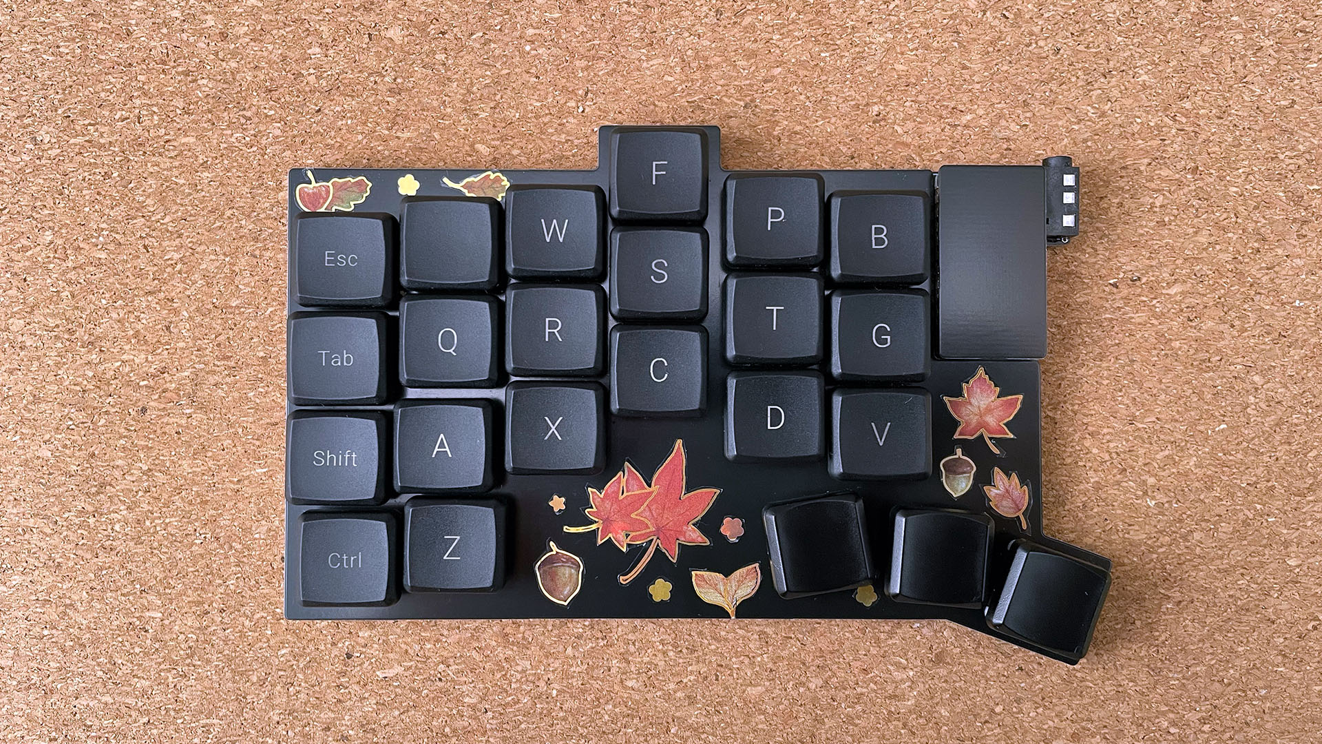
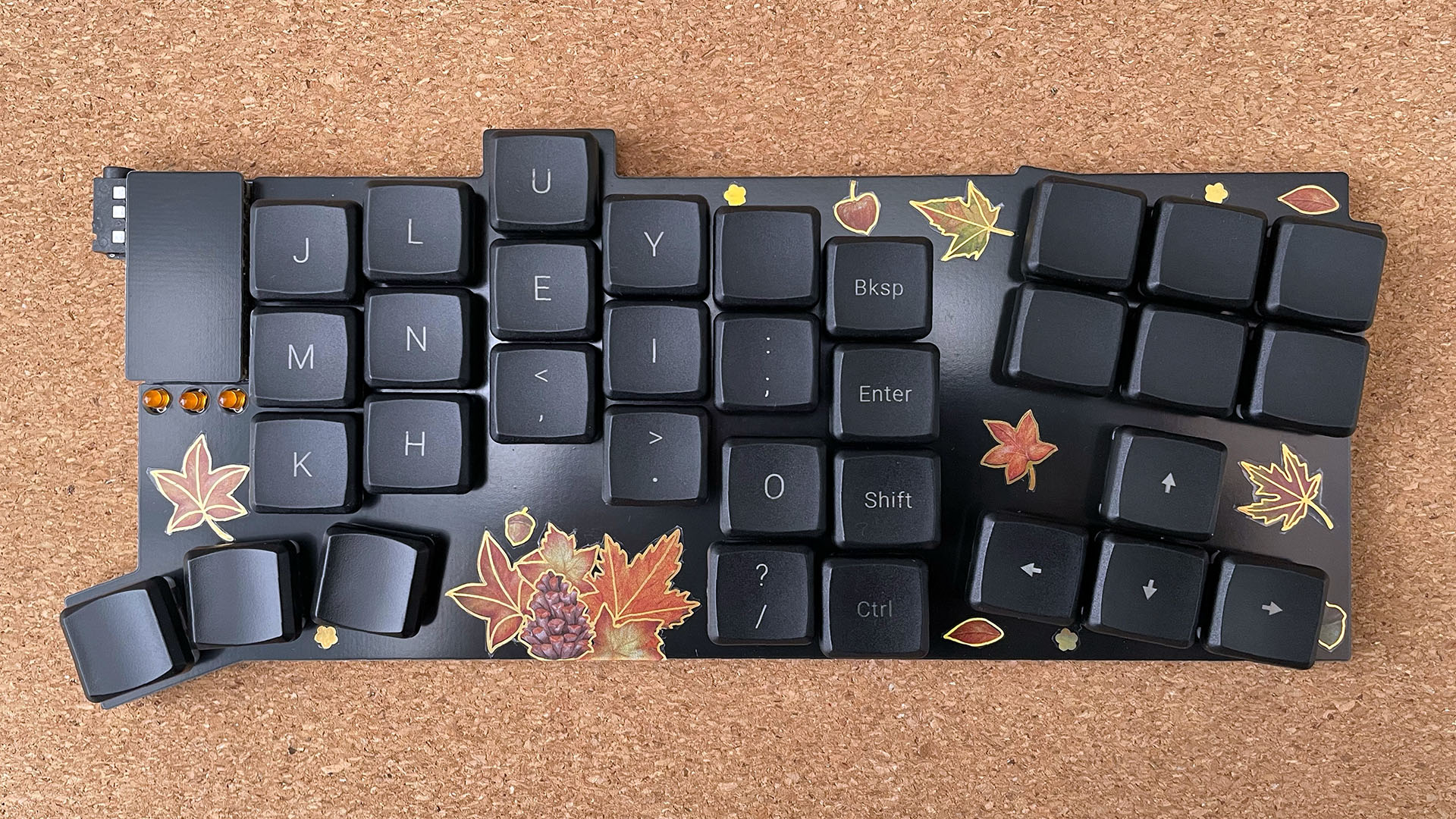
More images can be found here.
There are a few improvements that can be made:
ROW4 trace.Thanks to:
sevmyer for the open-source KiCad teardrop plugin which was very helpful given many KiCad teardrop plugins were for Kicad 6.| Qty | Value | Footprint | References |
|---|---|---|---|
| 27 | ~ | Keyboard:Switch3DRight | HR11, HR12, HR13, HR14, HR15, HR17, HR18, HR19, HR21, HR22, HR23, HR24, HR25, HR27, HR28, HR29 +11 |
| 17 | ~ | Keyboard:Switch3DLeft | HL11, HL12, HL13, HL14, HL15, HL21, HL22, HL23, HL24, HL25, HL31, HL32, HL33, HL34, HL41, HL42 +1 |
| 6 | ~ | Keyboard:SwitchDoubleLeft | HL16, HL26, HL35, HL36, HL45, HL46 |
| 1 | 11 | Keyboard:Switch | SW11 |
| 1 | 12 | Keyboard:Switch | SW12 |
| 1 | 13 | Keyboard:Switch | SW13 |
| 1 | 14 | Keyboard:Switch | SW14 |
| 1 | 15 | Keyboard:Switch | SW15 |
| 1 | 16 | Keyboard:SwitchDoubleRight | SW16 |
| 1 | 17 | Keyboard:Switch | SW17 |
| 1 | 18 | Keyboard:Switch | SW18 |
| 1 | 19 | Keyboard:Switch | SW19 |
| 1 | 21 | Keyboard:Switch | SW21 |
| 1 | 22 | Keyboard:Switch | SW22 |
| 1 | 23 | Keyboard:Switch | SW23 |
| 1 | 24 | Keyboard:Switch | SW24 |
| 1 | 25 | Keyboard:Switch | SW25 |
| 1 | 26 | Keyboard:SwitchDoubleRight | SW26 |
| 1 | 27 | Keyboard:Switch | SW27 |
| 1 | 28 | Keyboard:Switch | SW28 |
| 1 | 29 | Keyboard:Switch | SW29 |
| 1 | 31 | Keyboard:Switch | SW31 |
| 1 | 32 | Keyboard:Switch | SW32 |
| 1 | 33 | Keyboard:Switch | SW33 |
| 1 | 34 | Keyboard:Switch | SW34 |
| 1 | 35 | Keyboard:SwitchDoubleRight | SW35 |
| 1 | 36 | Keyboard:SwitchDoubleRight | SW36 |
| 1 | 37 | Keyboard:Switch | SW37 |
| 1 | 38 | Keyboard:Switch | SW38 |
| 1 | 39 | Keyboard:Switch | SW39 |
| 1 | 41 | Keyboard:Switch | SW41 |
| 1 | 42 | Keyboard:Switch | SW42 |
| 1 | 43 | Keyboard:Switch | SW43 |
| 1 | 45 | Keyboard:SwitchDoubleRight | SW45 |
| 1 | 46 | Keyboard:SwitchDoubleRight | SW46 |
| 1 | 47 | Keyboard:Switch | SW47 |
| 1 | 48 | Keyboard:Switch | SW48 |
| 1 | 49 | Keyboard:Switch | SW49 |
| 1 | EliteC | Keyboard:EliteC | U1 |
| 1 | H1 | Keyboard:RightPlate | H1 |
| 1 | H2 | Keyboard:LeftPlate | H2 |
| 1 | H2 | Keyboard:ControllerPlate | H3 |
| 1 | J1 | Keyboard:Jumper | JP1 |
| 1 | J2 | Keyboard:JumperSplit | JP2 |
| 1 | J3 | Keyboard:Jumper | JP3 |
| 1 | J4 | Keyboard:JumperSplit | JP4 |
| 1 | LED1 | Keyboard:HLMP-1401 | D1 |
| 1 | LED2 | Keyboard:HLMP-1401 | D2 |
| 1 | LED3 | Keyboard:HLMP-1401 | D3 |
| 1 | PTS526 | Keyboard:PTS526 | SWRST1 |
| 1 | R1 | Keyboard:SDR18 | R1 |
| 1 | R2 | Keyboard:SDR18 | R2 |
| 1 | R3 | Keyboard:SDR18 | R3 |
| 1 | R4 | Keyboard:SDR18 | R4 |
| 1 | R5 | Keyboard:SDR18 | R5 |
| 1 | TRRS | Keyboard:PJ-320A | J1 |
It measures 216.5 × 96 mm and has 2 copper layers, 1.6 mm thick.
103 parts. The full list of its parts is on this page, with links to each part's symbol and footprint where PCBKit's library has them.
From the mylestunglee/articulation70 repository on GitHub, at the commit this page was made from: the board is pcb/keyboard.kicad_pcb and its schematic controller_plate/plate.kicad_sch. PCBKit opens the board in the browser, with nothing to install.
Its repository states no licence, so its author keeps all rights: ask mylestunglee before reusing the design.
pierrechevalier83/ferris
A low profile split keyboard designed to satisfy one single use case elegantly

shorepine/tulipcc
The Tulip Creative Computer and AMYboard - portable Python synthesizers


LouWii/ErgoMax
Custom ergo split keyboard project, based on ErgoDox, with hot swap sockets

Orange-Murker/parametric_speaker
A directional speaker with a driver based on STM32

afternoonlabs/BreezeKeyboard
Breeze is a split mechanical keyboard with a column-staggered layout. With a focus on productivity, Breeze features a full 6x4 alphanumeric layout, arrow keys, and an extra 6 key cluster for typing and coding.

tebl/BulkyMIDI-32
A HW build of the MT32-PI project, allowing you to emulate a Roland MT-32 using a Raspberry Pi. Includes enough additional modules to build a MIDI-mountain as well as adapters for connecting to most things retro.
