
4 layers25.9 × 63.9 mm
Easyduino ESP32S3
Hanqaqa/Easyduino
Easily dive into different PCB KiCad designs of the most popular microcontroller devboards
35 parts755CERN-OHL-P-2.0

 mwrnd/OpenCAPI-to-PCIe_x4_Host_and_Endpoint2
OpenCAPI to PCIe x4 Host and Endpoint
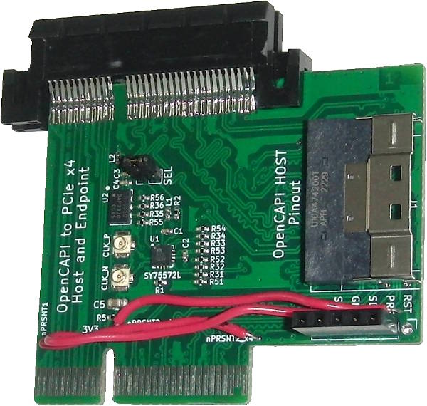
OpenCAPI PCIe x4 Host and Endpoint is an open-source printed circuit board by mwrnd, from the mwrnd/OpenCAPI-to-PCIe_x4_Host_and_Endpoint repository on GitHub, published under the BSD-2-Clause licence. It is a 4-layer board of 60 × 50.8 mm with 35 parts on 92 nets, routed with 2,526 tracks and 252 vias.
It is built around the SY75572LMG. Its parts include 16 resistors, 6 connectors, 5 capacitors, 2 ICs and 2 inductors. It belongs with the computers and single-board computers boards of this library.
Work-In-Progress: Design being tested.
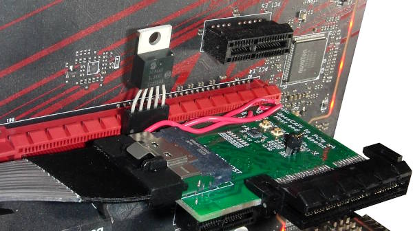
Designed to test simultaneous PCIe Host and Endpoint operation with the Innova-2.
There are two PCIE4 blocks in the column of the Innova-2's OpenCAPI Quads.
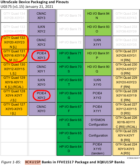
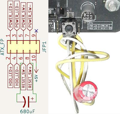
The GTY Transceivers connected to the OpenCAPI Connector are in a column that does not contain the Configuration Block so it is impossible for the FPGA to be programmed within the 100ms PCIe power-up time limit. Motherboard boot must be delayed to allow the FPGA to configure itself before PCIe devices are enumerated. This can be accomplished by toggling the POWER button, then pressing and holding the RESET button for a second before releasing it. Or, connect a capacitor across the reset pins of an ATX motherboard's Front Panel Header.
OpenCAPI-compatible SlimSAS 8x uses a Host version of the OpenCAPI Carrier pinout from the ADM-PCIE-9V5 User Manual (Pg15-19of38).
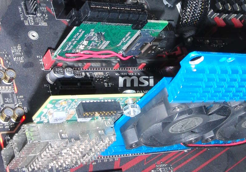
TODOThe innova2_xdma_opencapi project includes the ability to test I2C.
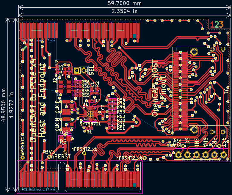
All differential pairs are length-matched to within 1mm intra-pair (N-to-P) and each group of differential pairs (e.g., TX0-to-TX3) is similarly matched to within 1mm.
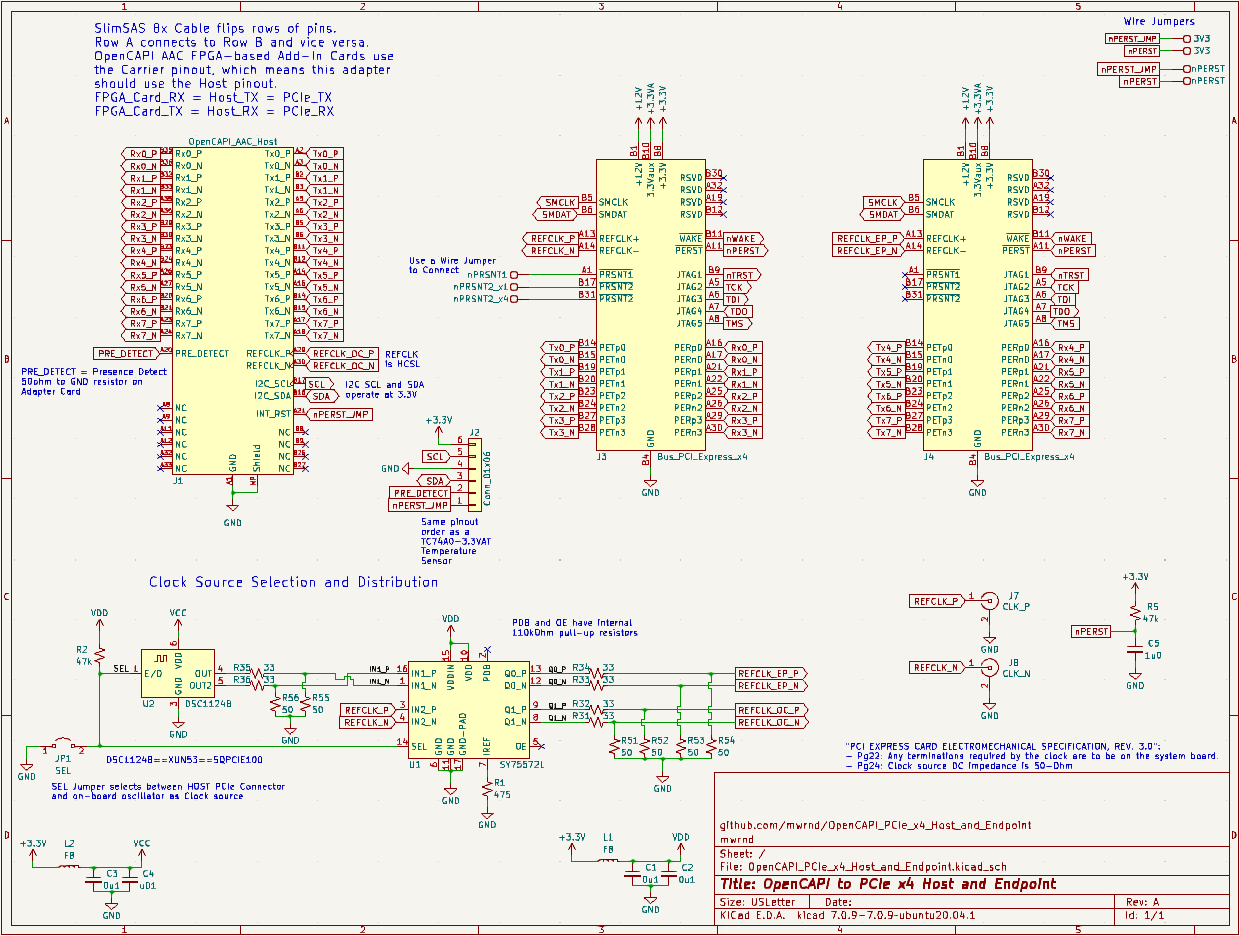
| Designator(s) | Part Number | Quantity | Value | Footprint | Availability |
|---|---|---|---|---|---|
| U1 | SY75572LMG | 1 | N/A | QFN-16-1EP_3x3mm_P0.5mm | DigiKey |
| U2 | DSC1124BI2-100-0000 | 1 | N/A | OSC_SMD_IDT_JS6-6_5.0x3.2mm_P1.27mm | DigiKey |
| J1 | U10A474240T | 1 | N/A | SlimSAS_8x_RA_U10-A474 | DigiKey |
| J2 | PPPC061LFBN-RC | 1 | N/A | PinHeader_1x06_P2.54mm_Vertical | DigiKey |
| J4 | 2-2387405-2 | 1 | N/A | PCIe x4 Straddle Mount w/ Open End | DigiKey |
| JP1 | 2PH1-02-UA | 1 | N/A | PinHeader_1x02_P2.00mm_Vertical | DigiKey |
| R31 to R36 | RT0402FRE0733RL | 6 | 33-Ohm | Resistor_SMD_R_0402_1005Metric | DigiKey |
| R51 to R56 | RT0402FRE0749R9L | 6 | 49.9-Ohm | Resistor_SMD_R_0402_1005Metric | DigiKey |
| R1 | RT0402FRE07475RL | 1 | 475-Ohm | Resistor_SMD_R_0402_1005Metric | DigiKey |
| R2, R5 | RT0402FRE0751KL | 2 | 51k-Ohm | Resistor_SMD_R_0402_1005Metric | DigiKey |
| L1, L2 | BLM15PX601SN1D | 2 | 600@100MHz | Resistor_SMD_R_0402_1005Metric | DigiKey |
| C4 | KGM05AR71C103KH | 1 | 0.01uF | Capacitor_SMD_C_0402_1005Metric | DigiKey |
| C1, C2, C3 | KGM05AR51A104KH | 3 | 0.1uF | Capacitor_SMD_C_0402_1005Metric | DigiKey |
| C5 | CL21B105KAFNNNE | 1 | 1uF | Capacitor_SMD_C_0805_2012Metric | DigiKey |
| J7, J8 | 2337019-1 | 2 | U.FL(UMCC) | U.FL_Hirose | DigiKey |
| Jumper | SPN02SYBN-RC | 1 | N/A | 2mm Shunt | DigiKey |
Optional: TC74Ax-3-3VAT I2C Temperature Sensor for testing I2C.
Use needle-nosed pliers to remove the PCIe x4 Connector's mounting post.
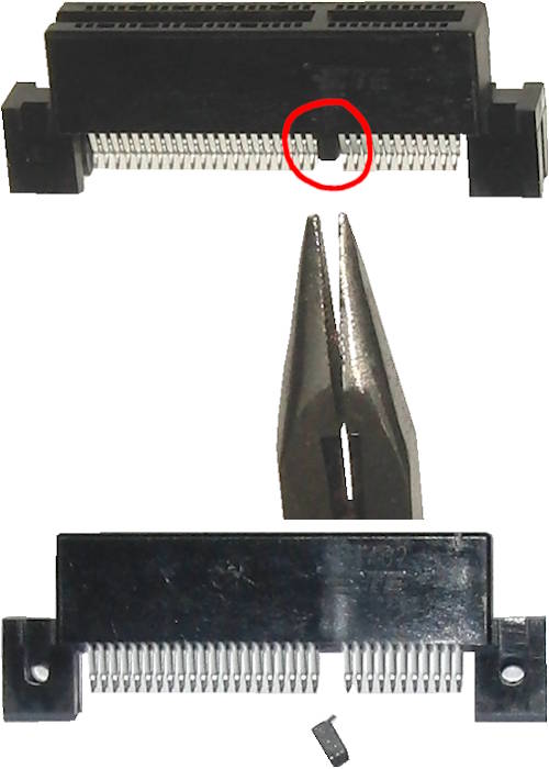
Three wire jumpers are needed to connect 3V3==3V3_PCIe, nPERST==RST, and nPRSNT1==nPRSNT2_x4.
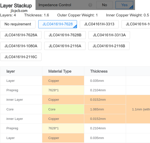
4-Layer PCB stackup taken from JLCPCB.
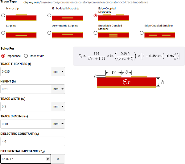
Differential Impedance parameters were calculated using the DigiKey Online Calculator.
| Qty | Value | Footprint | References |
|---|---|---|---|
| 6 | 33 | Resistor_SMD:R_0402_1005Metric_Pad0.72x0.64mm_HandSolder | R31, R32, R33, R34, R35, R36 |
| 6 | 50 | Resistor_SMD:R_0402_1005Metric_Pad0.72x0.64mm_HandSolder | R51, R52, R53, R54, R55, R56 |
| 3 | 0u1 | Capacitor_SMD:C_0402_1005Metric_Pad0.74x0.62mm_HandSolder | C1, C2, C3 |
| 2 | 47k | Resistor_SMD:R_0402_1005Metric_Pad0.72x0.64mm_HandSolder | R2, R5 |
| 2 | Bus_PCI_Express_x4 | Connector_PCBEdge:BUS_PCIexpress_x4 | J3, J4 |
| 2 | FB | Resistor_SMD:R_0402_1005Metric_Pad0.72x0.64mm_HandSolder | L1, L2 |
| 1 | 0 | Resistor_SMD:R_0402_1005Metric_Pad0.72x0.64mm_HandSolder | R3 |
| 1 | 1u0 | Capacitor_SMD:C_0805_2012Metric_Pad1.18x1.45mm_HandSolder | C5 |
| 1 | 475 | Resistor_SMD:R_0402_1005Metric_Pad0.72x0.64mm_HandSolder | R1 |
| 1 | CLK_N | U.FL_w_Label:U.FL_Hirose_w_Label | J8 |
| 1 | CLK_P | U.FL_w_Label:U.FL_Hirose_w_Label | J7 |
| 1 | Conn_01x06 | Connector_PinHeader_2.54mm:PinHeader_1x06_P2.54mm_Vertical | J2 |
| 1 | DSC1124B | Oscillator:Oscillator_SMD_IDT_JS6-6_5.0x3.2mm_P1.27mm | U2 |
| 1 | OpenCAPI_AAC_Host | SlimSAS_8x:SlimSAS_8x_RA_U10-A474 | J1 |
| 1 | SEL | Connector_PinHeader_2.00mm:PinHeader_1x02_P2.00mm_Vertical | JP1 |
| 1 | SY75572L | Package_DFN_QFN:QFN-16-1EP_3x3mm_P0.5mm_EP1.45x1.45mm_ThermalVias | U1 |
| 1 | nPRSNT1 | TestPoint:TestPoint_THTPad_D1.0mm_Drill0.5mm | TP1 |
| 1 | nPRSNT2_x1 | TestPoint:TestPoint_THTPad_D1.0mm_Drill0.5mm | TP2 |
| 1 | nPRSNT2_x4 | TestPoint:TestPoint_THTPad_D1.0mm_Drill0.5mm | TP3 |
| 1 | u01 | Capacitor_SMD:C_0402_1005Metric_Pad0.74x0.62mm_HandSolder | C4 |
Hanqaqa/Easyduino
Easily dive into different PCB KiCad designs of the most popular microcontroller devboards


Alia5/PiCCANTE
PiCCANTE is a powerful tool for exploring and reversing CAN busses of vehicles, based on Raspberry Pi Pico (any model)


Sgw32/KungFuSID
Kung Fu SID is a firmware based on Kung Fu Flash which allows SID emulation
It measures 60 × 50.8 mm and has 4 copper layers, 1.61 mm thick.
35 parts, built around the SY75572LMG. The full list of its parts is on this page, with links to each part's symbol and footprint where PCBKit's library has them.
From the mwrnd/OpenCAPI-to-PCIe_x4_Host_and_Endpoint repository on GitHub, at the commit this page was made from: the board is OpenCAPI_PCIe_x4_Host_and_Endpoint.kicad_pcb and its schematic OpenCAPI_PCIe_x4_Host_and_Endpoint.kicad_sch. PCBKit opens the board in the browser, with nothing to install.
Its repository publishes it under the BSD-2-Clause licence: you may reuse it on that licence's terms (keep the author's notice, and for a copyleft licence share your changes alike).