4 layers39.3 × 61.8 mm
MCL64
MicroCoreLabs/Projects
Ted Fried's MicroCore Labs Projects - FPGA CPU cores and emulators for the 8088, 8086, 8051, 6502, 68000, Z80, Risc-V, and also Typewriter and EPROM Emulator projects.
9 parts534
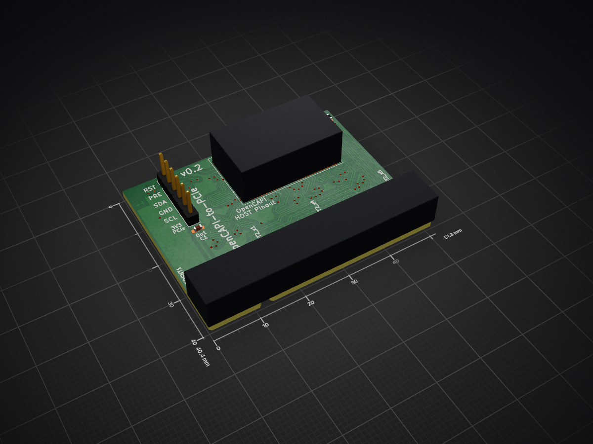
 mwrnd/OpenCAPI-to-PCIe2
OpenCAPI-Compatible SlimSAS 8x to PCIe Endpoint Adapter
OpenCAPI to PCIe is an open-source printed circuit board by mwrnd, from the mwrnd/OpenCAPI-to-PCIe repository on GitHub, published under the GPL-2.0 licence. It is a 4-layer board of 51.3 × 40.4 mm with 9 parts on 68 nets, routed with 1,607 tracks and 145 vias.
Its parts include 3 connectors, 1 capacitor and 1 resistor. It belongs with the computers and single-board computers and interfaces and adapters boards of this library.
The Open Coherant Accelerator Processor Interface (OpenCAPI) was a standard that had FPGA-based Advanced Accelerated Cable (AAC) Add-In cards such as ADM-PCIE-9H3, ADM-PCIE-9H7, ADM-PCIE-9V3, ADM-PCIE-9V5, BittWare XUP-VV4, BittWare XUP-VVH, and Nvidia Innova-2 Flex.
The OpenCAPI SlimSAS interface is based on PCI-Express. This project is an adapter capable of connecting such FPGA boards to host systmes with PCIe.
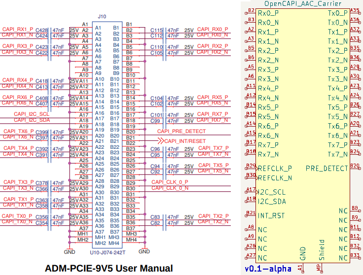
This design uses the OpenCAPI pinout from the ADM-PCIE-9V5 User Manual (Pg15-19of38):
The only OpenCAPI board I have to test against is the Innova-2 MNV303212A-ADLT Rev:A2 and I designed the OpenCAPI-to-PCIe_for_MNV303212A_RevA2 project as an optimized variant of this design for that board.
The current v0.2 release of this project worked with the First Release of the innova2_xdma_opencapi project:
git clone --revision=348716249bafc39514cb1a422a8e2fb5f301f859 https://github.com/mwrnd/innova2_xdma_opencapi.git
wget https://github.com/mwrnd/innova2_xdma_opencapi/releases/download/v0.1/innova2_xdma_opencapi_bitstream.zip
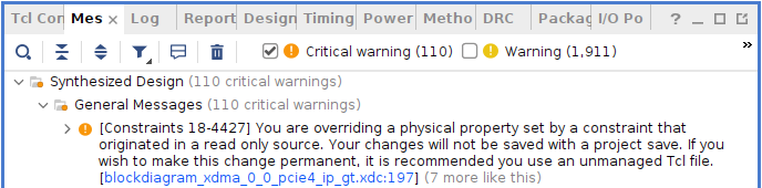
But, it required a non-standard GTY Channel to PCIe Lane mapping that Vivado complains about:
The OpenCAPI-to-PCIe_for_MNV303212A_RevA2 project is a version of this adapter optimized for the Innova-2 MNV303212A Rev:A2.
4-Layer PCB. Inner 2 layers are GND planes. Differential pairs are matched to a length of 65mm +/- 1mm both inter-pair and intra-pair (N-to-P).
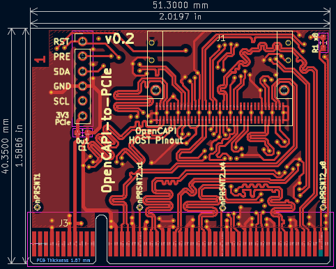
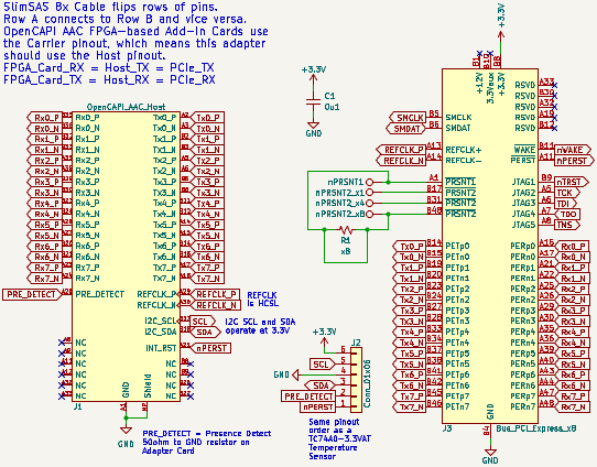
Refer to the ADM-PCIE-9V5 User Manual (Pg15-19of38). Useful High Speed Design presentation.
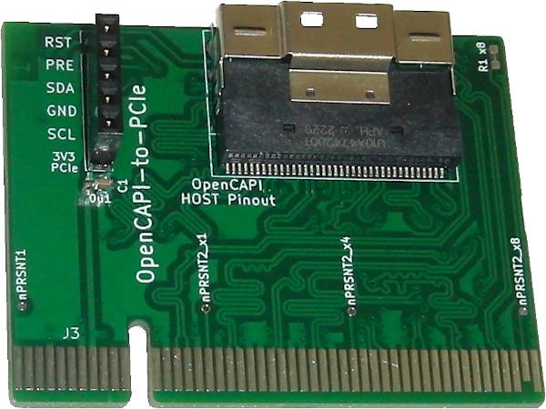
Only a single component is needed for the adapter, a U10A474200T/U10A474240T SlimSAS 8x Right-Angle SMD Connector.
A SlimSAS 8x Cable such as the 3M 8ES8-1DF21(Datasheet) is required to use the adapter with an OpenCAPI FPGA Board.
Resistor R1 is shorted to connect nPRSNT1 to nPRSNT2_x8. The trace can be scratched off and nPRSNT1 can be connected to nPRSNT2_x1 or nPRSNT2_x4 to limit the PCIe lane width.
Additional useful signals from the OpenCAPI connector are routed to a 6x1 0.1" Header (DigiKey). The pinout matches a TC74 I2C Temperature Sensor (DigiKey) for testing I2C. I2C pull-ups are on the AAC Add-in card. Note 3.3V is from the PCIe connector. PRE is a Presence Detect pin which is connected to GND via a 50-Ohm resistor on the OpenCAPI AAC Add-In card. RST is connected to PCIe/OpenCAPI RESET.
I am using values from JLCPCB.
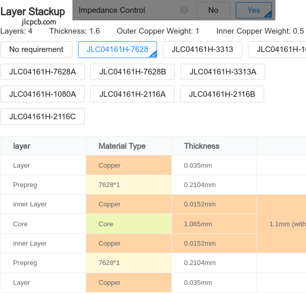
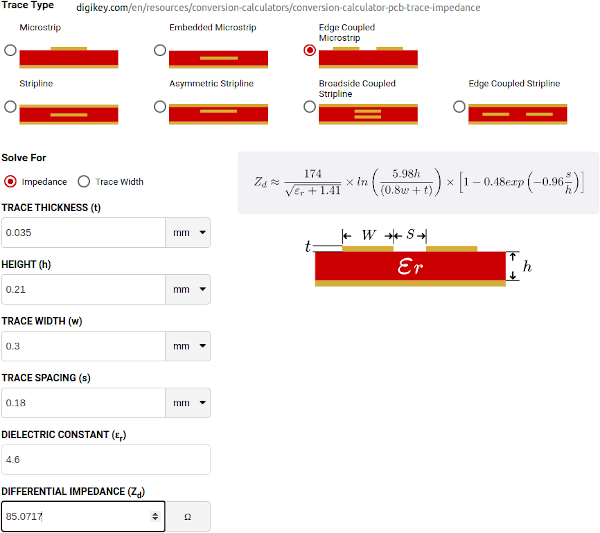
OpenCAPI uses 85ohm impedance cables. I played with the values until I got the loosest differential pair coupling that is manufacturable with larger tolerances.
| Qty | Value | Footprint | References |
|---|---|---|---|
| 1 | 0u1 | Capacitor_SMD:C_0603_1608Metric_Pad1.08x0.95mm_HandSolder | C1 |
| 1 | Bus_PCI_Express_x8 | Connector_PCBEdge:BUS_PCIexpress_x8 | J3 |
| 1 | Conn_01x06 | Connector_PinHeader_2.54mm:PinHeader_1x06_P2.54mm_Vertical | J2 |
| 1 | OpenCAPI_AAC_Host | SlimSAS_8x:SlimSAS_8x_RA_U10-A474 | J1 |
| 1 | nPRSNT1 | TestPoint:TestPoint_THTPad_D1.0mm_Drill0.5mm | TP1 |
| 1 | nPRSNT2_x1 | TestPoint:TestPoint_THTPad_D1.0mm_Drill0.5mm | TP2 |
| 1 | nPRSNT2_x4 | TestPoint:TestPoint_THTPad_D1.0mm_Drill0.5mm | TP3 |
| 1 | nPRSNT2_x8 | TestPoint:TestPoint_THTPad_D1.0mm_Drill0.5mm | TP5 |
| 1 | x8 | Resistor_SMD:R_0603_1608Metric_Pad0.98x0.95mm_HandSolder | R1 |
MicroCoreLabs/Projects
Ted Fried's MicroCore Labs Projects - FPGA CPU cores and emulators for the 8088, 8086, 8051, 6502, 68000, Z80, Risc-V, and also Typewriter and EPROM Emulator projects.

TobleMiner/HPE-FlexibleLOM-adapter
Adapter for using HPE FlexibleLOM cards in full height PCIe slots


BerkeleyHCI/PolymorphicBlocks
A Python-based hardware description language for PCBs for higher-level (block-diagram / system-architecture level) PCB design through libraries of directly reusable subcircuit generators.

agranlund/raven
Homemade MC68060 + DSP56303 Atari-compatible computer. Hardware, firmware, and software stack

m-kozlowski/airbridge
Wireless adapter for AirSense/AirCurve 10 devices

thorpej/pg68k
The 68k Playground, a 680x0-based home-brew computer with multiple CPU options

will127534/CSI-2-FourLane-HDMI-Extender
A simple MIPI CSI-2 extender with 4-lane support through HDMI cable
It measures 51.3 × 40.4 mm and has 4 copper layers, 1.61 mm thick.
9 parts. The full list of its parts is on this page, with links to each part's symbol and footprint where PCBKit's library has them.
From the mwrnd/OpenCAPI-to-PCIe repository on GitHub, at the commit this page was made from: the board is OpenCAPI-to-PCIe.kicad_pcb and its schematic OpenCAPI-to-PCIe.kicad_sch. PCBKit opens the board in the browser, with nothing to install.
Its repository publishes it under the GPL-2.0 licence: you may reuse it on that licence's terms (keep the author's notice, and for a copyleft licence share your changes alike).